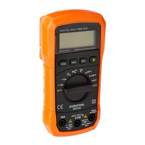
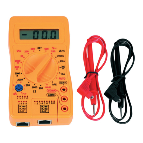
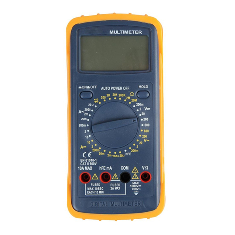
Duratool D03126 User manual

1
MODEL: D03126
Digital Multimeter with Backlight

2
CONTENTS
Page Number Description
3 Important Safety Information
3 What’s Included?
4 Overview
4 Front Panel Description
5General Specication
5 DC Voltage
5 DC Current
6 AC Voltage
6 Diode & Continuity
6 Resistance
6 Transistor hFE Test (0-1000)
6 Operation - DC Voltage Measurement
7 Operation - DC Current Measurement
7 Operation - AC Current Measurement
7 Operation - Resistance Measurement
7 Operation - Diode Test
7Operation - Transistor Test
8 Operation - Audible Continuity Test
8 Battery & Fuse Replacement
8 Cleaning

3
IMPORTANT SAFETY INFORMATION
Please read these instructions carefully before use and retain for future
reference.
Important safety information. Read the instructions carefully.
High voltage. Danger.
Ground.
Double Insulation (Class II safety equipment).
Fuse must be replaced as per the specication herein.
!
200mA/250V
• When using electrical appliances basic safety precautions should always be
followed.
• Do not exceed the protection limit values specied for each range range of
measurement.
• Never use the meter to measure voltages that might exceed 600V above earth
ground in category II installations.
• When the value scale to be measured is unknown beforehand, set the range
selector to the highest position.
• Before rotating the range selector to change the functions disconnect the test
leads from the circuit under test.
• When measuring a TV set or switching power supply, watch out for pulses in the
circuit that may damage the meter.
• Before working with and measuring voltages higher than 60V DC or 30V AC RMS,
keep your ngers behind the probe barriers.
• Before attempting to insert transistors for testing, always be sure that the test
leads have been disconnected from any measurement circuits.
• Components should not be connected to the hFE socket when making voltage
measurements with test leads.
• Do not perform resistance measurements on live circuits.
• The instrument can only be used in conjunction with the test leads supplied. If
necessary, they must be replaced with the same type and specication.
WHAT’S INCLUDED?
• One instruction manual
• One digital multimeter
• Set of test leads
• One 9V battery, NEDA 1604 6F22 006P type
• Holster (optional)
This meter is a handheld 3½ digital multimeter used for measuring DC and AC voltage,
DC current, resistsance, diode, transistor and continuity.

4
OVERVIEW
1
2
3
4
5
6
7
Front Panel Description
1 Display - 3½ digit, 7 segment, 15mm high LCD
2
Backlight - once pushed the backlight of the display will turn on. It will self-
turnoff after about ve seconds. To turn the backlight on again, just push the
button.
3Rotary switch - used to select functions and desired ranges as well as turn
the meter on or off.
4“VΩmA” jack - plug in the connector for red (positive) test lead for voltage,
resistance and current (except 10A) measurements.
5“COM” jack - plug in the connector for the black (negative) test leads.
6“10A” jack - plug in the connector for the red test lead for 10A measurement.
7Hold button - once pushed, the display will keep the last reading and “H”
symbol will appear on the LCD until the button is pushed again.

5
GENERAL SPECIFICATION
Max. voltage between terminals and
earth ground CAT II 600V
Fuse Protection F 200mA / 250V
Power 9V battery, NEDA 1604 or 6F22
Display LCD, 1999 counts, updates 2-3 seconds
Measuring Method Dual-slope integration A/D converter
Overrange Indication Only gure “1” on the display
Polarity Indication “-” displayed for negative polarity
Operating Environment 0°C to 40°C
Storage Temperature -10°C to 50°C
Low battery indication “ ” appears on the display
Size 138mm x 69mm x 31mm
Weight Approx 170g
Accuracy is specied for a period of one year after calibration and at 18 to 28°C (64°F
to 82°F) with relative humidity to 80%.
DC VOLTAGE
Range Resolution Accuracy
200mV 100µV ± 0.5% of rdg ± 2 digits
2V 1mV ± 0.5% of rdg ± 2 digits
20V 10mV ± 0.5% of rdg ± 2 digits
200V 100mV ± 0.5% of rdg ± 2 digits
600V 1V ± 0.8% of rdg ± 2 digits
Overload protection: 250V rms. For 200mV range and 600V dc or rms, ac for other
ranges.
DC CURRENT
Range Resolution Accuracy
200µA 0.1µA ± 1% of rdg ± 2 digits
2mA 1µA ± 1% of rdg ± 2 digits
20mA 10µA ± 1% of rdg ± 2 digits
200mA 100µA ± 1.5% of rdg ± 2 digits
10A 10mA ± 3% of rdg ± 2 digits
Overload protection: F 200mA/250V fuse (10A range unfused).

6
AC VOLTAGE
Range Resolution Accuracy
200V 100mV ± 1.2% of rdg ± 10 digits
600V 1V ± 1.2% of rdg ± 10 digits
Overload protection: 600V DC or RMS. AC for all ranges.
Frequency range: 40Hz to 400Hz.
Response: average responding, calibrated in rms of a sine wave.
DIODE & CONTINUITY
Range Description
If continuity exists (about less than 1.5kΩ), the built-in buzzer will sound.
Shows the approximate forward voltage drop of the diode.
RESISTANCE
Overload protection: 250V DC or RMS, AC.
Range Resolution Accuracy
200Ω 0.1Ω ± 0.8% of rdg ± 3 digits
2kΩ 1Ω ± 0.8% of rdg ± 2 digits
20kΩ 10Ω ± 0.8% of rdg ± 2 digits
200kΩ 100Ω ± 0.8% of rdg ± 2 digits
2MΩ 1kΩ ± 1.0% of rdg ± 2 digits
Maximum open circuit voltage: 3.2V
Overload protection: 250V DC or RMS, AC for all ranges.
TRANSISTOR hFE TEST (0-1000)
Range Test Range Test Current Test Voltage
NPN & PNP 0-1000 lb = 10µA Vce = 3V
OPERATION - DC VOLTAGE MEASUREMENT
• Connect the red test lead to the “VΩmA” jack and the black lead to the “COM”
jack.
• Set the rotary switch at the desired DCV position. If the voltage to be measured is
not known beforehand, set the range switch at the highest range position and then
reduce it until a satisfactory resolution is obtained.
• Connect the test leads across the source or load being measured.
• Read the voltage value on the LCD display along with the polarity of the red lead
connection.

7
OPERATION - DC CURRENT MEASUREMENT
• Connect the red test lead to the “VΩmA” jack and the black test lead to the “COM”
jack.
• Note: for measurements between 200mA and 10A, remove the red lead to the
“10A” jack.
• Set the rotary switch at the desired DCA position.
• Open the circuit in which the current is to be measured and connect the test leads
in series with the circuit.
• Read the current value on the LCD along with the polarity of th red lead
connection.
OPERATION - AC VOLTAGE MEASUREMENT
• Connect the red test lead to the “VΩmA” jack and the black test lead to the “COM”
jack.
• Set the rotary switch at the desired ACV position.
• Connect test leads across the source or load being measured.
• Read the voltage on the LCD.
OPERATION - RESISTANCE MEASUREMENT
• Connect the red test lead to the “VΩmA” jack and the black test lead to the “COM”
jack.
• Note: the polarity of the red lead is positive.
• Set the rotary switch at the desired “Ω” range position.
• Connect the test leads across the resistor to be measured and read the LCD.
• If the resistance being measured is connected to a circuit, turn off the power and
discharge all capacitors before applying test probes.
OPERATION - DIODE TEST
• Connect the red test lead to the “VΩmA” jack and the black test lead to the “COM”
jack.
• Note: the polarity of the red lead is positive.
• Set the rotary switch at the “ ” position.
• Connect the red test lead to the anode of the diode to be tested and the black test
lead to the cathode of the diode.
• The approximate forward voltage drop of the diode will be displayed. If the
connection is reversed, only gure “1” will be shown.
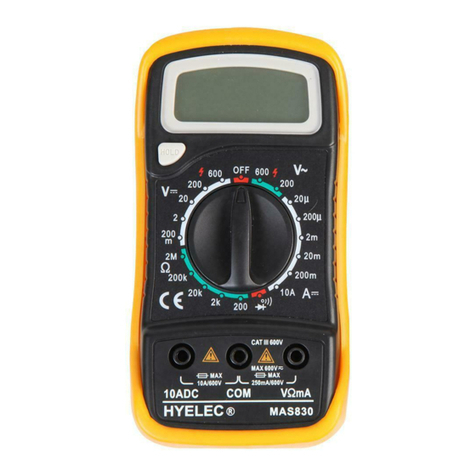
OPERATION - TRANSISTOR TEST
• Set the rotary switch at the “hFE” position.
• Determine whether the transistor under testing is NPN or PNP and locate the
emitter, base and collector leads. Insert the leads into the proper holes of the hFE
socket on the front panel.
• Read the approximate hFE value and the test condition of the base current 10µA
and Vce 3V.
8
OPERATION - AUDIBLE CONTINUITY TEST
• Connect the red test lead to the “VΩmA” jack and the black test lead to the “COM”
jack.
• Set the range switch to “ ” position.
• Connect the test leads to the two points of the circuit to be tested. If continuity
exists, the built-in buzzer will sound.
BATTERY & FUSE REPLACEMENT
• If the “ ” symbol appears on the display it indicates that the battery shouid be
replaced.
• To replace a battery and fuse (200mA/250V) remove the two screws in the bottom
of the case.
• Before opening the case, always disconnect the test leads from all energised
circuits.
• Remove the old fuse or battery and replace it with a new one of the same
specication.
• Be careful to observe the battery polarity.
• Never use the meter unless the back cover is in place and securely fastened.
CLEANING
• Use a soft, clean, dry cloth to clean the meter.
• Do not use any chemicals, abrasives or solvents that may damage the meter.
INFORMATION ON WASTE DISPOSAL FOR CONSUMERS OF
ELECTRICAL & ELECTRONIC EQUIPMENT.
This symbol indicate that separate collection of Waste Electrical and
Electronic Equipment (WEEE) or waste batteries is required. Do not dispose
of these items with general household waste. Separate for the treatment,
recovery and recycling of the materials used. Waste batteries can be
returned to any waste battery recycling point which are provided by most
battery retailers. Contact your local authority for details of the battery and
WEEE recycling schemes available in your area.
Made in China. PR2 9PP
V 1.0
Table of contents
Other Duratool Multimeter manuals

Duratool
Duratool D03305 User manual

Duratool
Duratool D03127 User manual

Duratool
Duratool D03131 User manual

Duratool
Duratool D03124 User manual

Duratool
Duratool D03143 User manual

Duratool
Duratool D03046 Assembly instructions

Duratool
Duratool D03046 User manual

Duratool
Duratool D03125 User manual

Duratool
Duratool D03143 User manual

Duratool
Duratool D03145 User manual