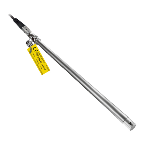
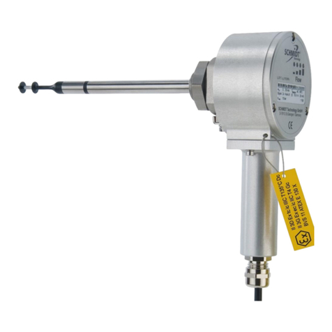
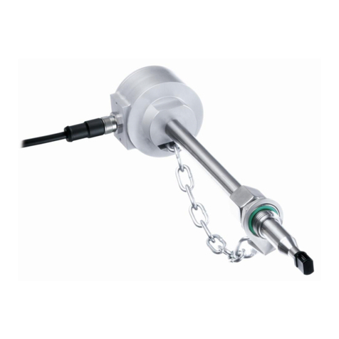
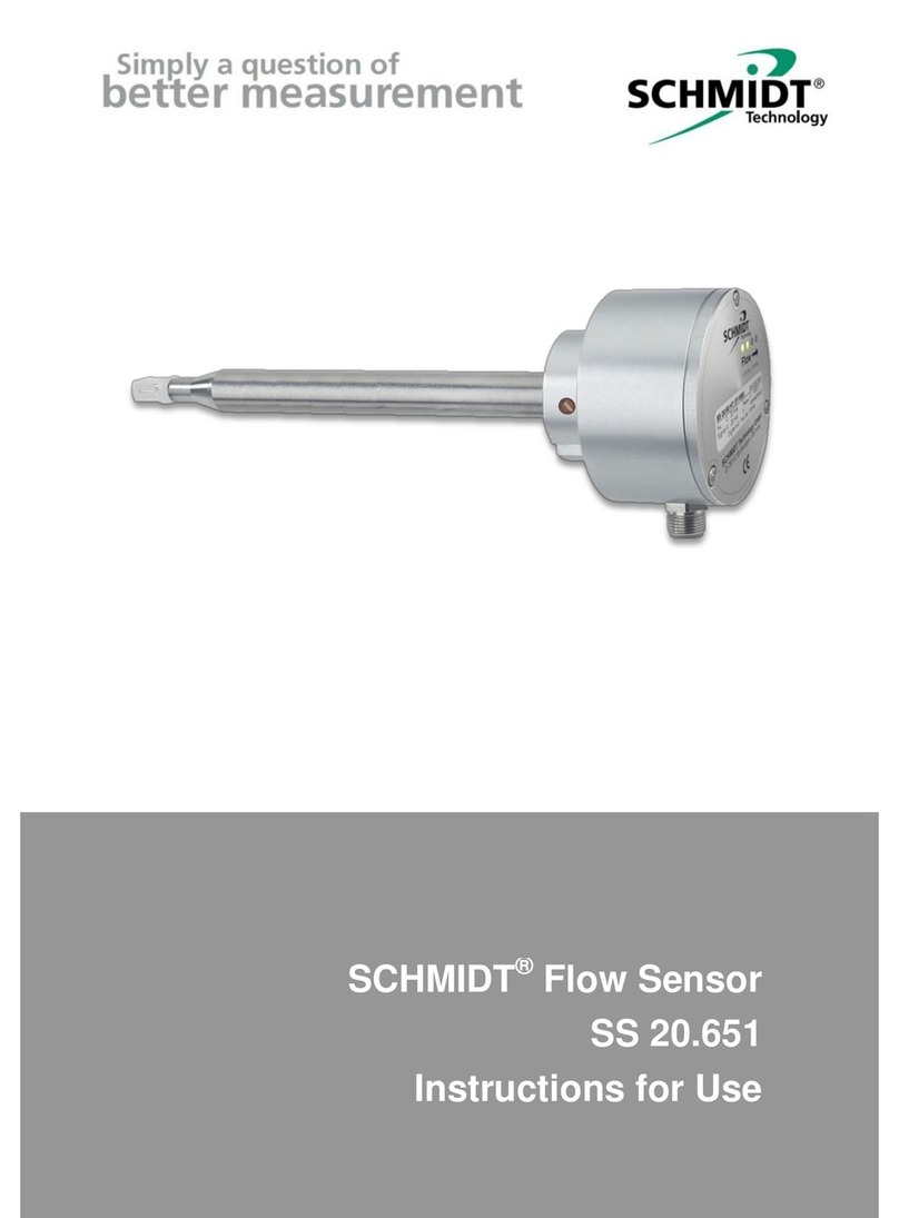
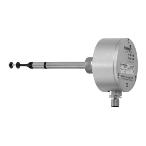
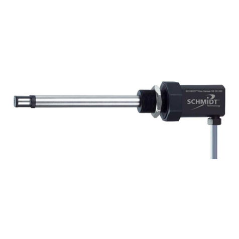
Schmidt SS 20.515 LED User manual

SCHMIDT®Flow Sensor
SS 20.515 LED
Instructions for Use

Instructions for use SS 20.515 Page 2
SCHMIDT®Flow Sensor
SS 20.515 LED
Table of Contents
1Important Information ......................................................................3
2Application Range ...........................................................................4
3Mounting Instructions ......................................................................4
4Electrical Connection.......................................................................7
5Signaling..........................................................................................9
6Startup...........................................................................................11
7Information on Continuous Operation ...........................................12
8Service Information........................................................................13
9Technical Data...............................................................................14
10 Declaration of Conformity..............................................................15
Imprint:
Copyright 2017 SCHMIDT Technology
All rights reserved
Revision: 551743.02
Errors and technical modifications subject to change

Instructions for use SS 20.515 Page 3
1 Important Information
These instructions for use contain all required information for a fast
commissioning and a safe operation of SCHMIDT®flow sensors of the
SS 20.515 LED type:
These instructions for use must be read completely and observed
carefully, before putting the unit into operation.
Any claims under the manufacturer's liability for damage resulting
from non-observance or non-compliance with these instructions will
become void.
Tampering with the device in any way whatsoever - with the excep-
tion of the designated use and the operations described in these in-
structions for use - will forfeit any warranty and exclude any liability.
The unit is designed exclusively for the use described below (refer to
chapter 2). In particular, it is not designed for direct or indirect pro-
tection of personal and machinery.
SCHMIDT Technology cannot give any warranty as to its suitability
for certain purpose and cannot be held liable for accidental or se-
quential damage in connection with the delivery, performance or use
of this unit.
Symbols used in this manual
The symbols used in this manual are explained below.
Danger warnings and safety instructions - please read them!
Non-observance of these instructions may lead to personal
injury or malfunction of the device.
General information
All dimensions are given in mm.
!

Instructions for use SS 20.515 Page 4
2 Application Range
The SCHMIDT®flow sensor SS 20.515 LED (551550) is designed for
stationary use in clean rooms under atmospheric pressure conditions
and clean environmental conditions.
The sensor measures flow velocity of the measuring medium as stand-
ard velocity
1
(unit: m/s) relative to standard conditions of 1013.25 hPa
and 20 °C. Thus, the resulting output signal is independent of the pres-
sure and temperature of the medium to be measured.
The sensor is designed for the use inside closed rooms and is not suita-
ble for outdoor use.
3 Mounting Instructions
General information on handling
The flow sensor SS 20.515 LED is a sensitive measuring instrument.
Applying mechanical force to the sensor tip should be avoided.
The sensor tip can be damaged irreversibly due to mechanical
loads.
Leave the protective cap as long as possible attached during
mounting and handle the sensor with care.
For applications with an uncontrollable risk of touch, a special safety bar
can be mounted on the sensor (optional accessory: 531026).
Flow characteristics
To avoid false measurement results, appropriate installation conditions
must be guaranteed to ensure that the gas flow is supplied to the sensor
in a quiet (low in turbulence) state.
Correct measurements requires laminar2flow with as low turbu-
lence as possible.
1
Corresponds to the real velocity under standard conditions.
2
The term “laminar” means here an air flow low in turbulence (not according to its physical
definition saying that the Reynolds number is < 2300).
!
!

Instructions for use SS 20.515 Page 5
Assembly
For the assembly of the SCHMIDT®flow sensor SS 20.515 LED, five
different assembly versions optimized for use in cleanrooms are availa-
ble, in order to cover all the different applications (see Table 1).
First, the required holes, depending on the assembly version, must be
drilled, and the corresponding fixing socket must be mounted in that
hole. Then the connecting cable is introduced with its open into the fixing
socket from the cleanroom side until the cable bushing protrudes from
the fixture by only about 5 cm. Please note that after assembling the
sensor, there must still be room for this protruding cable length in the
void behind the assembly bushing. Now connect the sensor to the con-
necting cable (plug in and screw down spigot nut), insert it into the fixture
bushing and tighten the holding fixture screw by hand. Now the sensor
can still be aligned accurately by hand, if required. Finally, the holding
fixture screw must be tightened with a key wrench (wrench size 22) until
the sensor is sufficiently secured against twisting.
Prior to commissioning the sensor, remove the protective cap.
Assembly beneath a ceiling
The angled sensor is designed for assembly below the ceiling.
After the sensor has been inserted into the fixture bushing and the as-
sembly screw tightened (first only by hand), the sensor head will auto-
matically have an optimum position for the detection of the vertical
downdraft flow from the ceiling. Only the torsional angle of the sensor
arm in parallel to the ceiling must still be aligned. Then tighten the as-
sembly screw using the fork wrench (hold sensor, if necessary) until the
sensor is secured against twisting.
Assembly at a wall
The straight sensor is designed for assembly at a wall.
Insert sensor into the fixture bushing and thoroughly tighten the assem-
bly screw. No alignment to the flow is required, due to the omnidirection-
al measurement characteristic of the sensor head.
Instructions for use SS 20.515 Page 6
Type / Article No.
Drawing
Assembly
Mounting
Type 1
Threaded bush M25 with lock nut:
- For installation in ceilings, walls or
frames with a thickness from 1 to 22 mm.
- Opening with a Ø of 26 mm required for
fixing with lock nut.
- Or insert a thread M25 x 1.5 into ceiling.
Mounting
Type 2
Threaded bush M25 with threaded adapter
M25 x 1.5 for PG:
- For installation in frames with an existing
opening with PG21 thread
(e.g. sprinkler openings in profiles).
Mounting
Type 3
Threaded bush M25 with shank nut:
- For installation in frames with a thickness
from 21 to 40 mm, especially for ceiling
frames made of hollow profiles.
- Openings with a Ø of 26 mm and a Ø of
28.5 mm are necessary.
Mounting
Type 4
Welding bush:
- For welding to stainless steel ceilings or
walls.
Mounting
Type 5
Flanged bushing (pressure-tight till 300 mbar):
- For mounting under the ceiling or at a
wall with two screws M6.
- Opening in ceiling / wall required with a
Ø of 15 mm for cable and 2 threads M6.
Table 1

Instructions for use SS 20.515 Page 7
4 Electrical Connection
The SS 20.515 LED is equipped with a plug-in connector which is firmly
integrated into the enclosure. The connector has the following data:
Number of connection pins: 7 (plus shield connection of metallic housing)
Type: male
Locking of connecting cable: M9 spigot nut (on cable)
Model: Binder, series 712
Pin numbering:
View on connector of sensor
Figure 4-1
The pin assignment of the plug-in connector can be seen from the fol-
lowing Table 2.
Pin
Designation
Function
Wire colour
1
Power
Supply voltage: +UB
white
2
Aout Temp
Temperature output TM
brown
3
internal
-
green
4
internal
-
yellow
5
internal
-
grey
6
Aout Flow
Velocity signal wN
pink
7
GND
Supply voltage: Mass
blue
Shield
Electromechanical shielding
Shield meshwork
Table 2
All signals use GND as electric reference potential.
The wire colours mentioned in Table 2 are applicable for the use of a
SCHMIDT®cable (article no.: 505911-4, 535279, 535281).
The cable shield is connected to the metallic housings of the connector
and the sensor: It is coupled indirectly to GND (VDR
3
, in parallel with 100
nF) and should be connected to an anti-interference potential, e.g. GND
(depending on the shielding concept).
During electrical installation ensure that no voltage is applied
and inadvertent activation is not possible.
3
Voltage dependent resistor; breakdown voltage 27 V @ 1 mA
!

Instructions for use SS 20.515 Page 8
The appropriate protection class III (SELV) respective PELV
(EN 50178) has to be considered.
Operating voltage
The SS 20.515 LED is protected against a polarity reversal of the operat-
ing voltage.
It has a nominal operating voltage range of UB= 24 VDC ± 10 %.
Only operate the sensor within the defined operating voltage
range (21.6 … 26.4 VDC).
Undervoltage may result in malfunction, overvoltage may lead
to irreversible damage.
The specifications for the operating voltage are valid for the connection
to the sensor. Voltage drops generated due to line resistances must be
taken into account by the customer.
The typical operating current is approx. 60 mA and at most 100 mA.
Analog outputs
The analog outputs of the sensor (flow and temperature) are protected
against a short circuit towards both rails.
There are two output versions (selected by ordering):
Current interface:
Signal range
4
: 4 ... 20 mA
Type: high side driver, load resistance against GND
Maximum load resistance RL: 300 Ω
Maximum load capacitance CL: 10 nF
Maximum recommended cable length: 100 m
Wiring:
Figure 4-2
4
Error signaling 2 mA as specified in NAMUR NE 43
!
!

Instructions for use SS 20.515 Page 9
Voltage interface:
Signal range: 0 ... 10 V
Type: high side driver, load resistance against GND
Minimum load resistance RL: 10 kΩ
Maximum load capacitance CL: 10 nF
Maximum short-circuit current: 25 mA
Maximum recommended cable length: 10 m
Wiring:
Figure 4-3
Due to the resistance
5
RWof the connecting cable, the operating current
causes a voltage drop in each wire of the operating voltage, which may
adopt interfering values especially as so-called "mass offset" in the GND
wire.
This is why you have to make sure during installation that the original
lead of the sensor is kept as short as possible. Reconnection to cables
with wider cross-sections near the sensor is recommended.
The voltage drop in the GND wire of the connecting cable
during operation can substantially falsify the analog signal
at the voltage output.
5 Signaling
The sensor SS 20.515 LED reproduces the respective measuring quanti-
ty linearly on the relevant analog output. The representation specification
depends both on the measuring quantity and the output characteristics
(see figures in the following tables).
Representation of measuring range
When measuring flow velocity wN, measurement ranges from zero
flow to the selectable end of the measuring range wN,max (= 100 %,
see Table 3).
5
The specific resistance of the lead of the nominal cable (0.14 mm2) is 0.138 /m (20°C);
at L = 10 m a current of IB,max = 100 mA can cause a voltage drop up to 166 mV.
!

Instructions for use SS 20.515 Page 10
Voltage interface (U) wN
Current interface (I) wN
U
Out
[V]
0
110
w
N
[%]
10
0
20
11
40
80
60
100
4
2
6
8
Out
N
NU
V
w
w 10max,
)4(
16 max, mAI
mA
w
wOut
N
N
Table 3
The measuring range of the temperature of the medium is fixed be-
tween -20 and +70 °C (see Table 4).
Voltage interface (U) TM
Current interface (I) TM
CU
V
TOutM )20
10
90
(
CmAI
mA
TOutM ]20)4(
16
90
[
Table 4
Note regarding commissioning:
Normally the temperature output provides approx. 5 V or 12 mA be-
cause the typically prevailing room temperature of approx. 25 °C cor-
responds to half of the measuring range.
Overflow:
Flow speeds which exceed measuring range are furthermore output
in a linear way up to 110 % of measuring range (end value + 10 %).
For higher values of flow the output signal remains constant.
Temperature of medium outside of the specification range
Operation outside the specified limits may damage the sensor and is
displayed as follows (see also graphics in Table 4):
110 wN [%]
020 40 8060 100
IOut
[mA]
20
4
21,6
12
8
16
UOut
[V]
075 T
M [°C]
10
4
2
20
11
40 7060-20
6
8
075
20 40 7060-20
IOut
[mA]
T
M [°C]
20
4
8
22
1212
16
2
075
20 40 7060-20 0 75
20 40 7060-20

Instructions for use SS 20.515 Page 11
oTemperature of the medium below -20 °C
The analog output for TMswitches to error (0 V or 2 mA).
The analog output for wNswitches to error (0 V or 2 mA).
oTemperature of the medium above +70 °C
Measuring values above TM,max are output in a linear way up to
approx. 75 °C (10.6 V or 21.6 mA).
oTemperature of the medium above +75 °C
6
The analog output for wNsignals an error (0 V or 2 mA).
The analog output TMswitches directly to the maximum output
values of 11 V or 22 mA.
Error signaling:
The voltage interface is set to 0 V.
The current interface outputs 2 mA.
LED light ring
The SS 20.515 LED indicates its current operating state via a light ring in
the holder using coloured light code:
Colour signal
Function / failure
None
Supply voltage: none, reversed, too low
Green pulsing (2 Hz)
Supply voltage: too high
Red pulsing (2 Hz)
Sensor defective
Red blazing
Only with current interface: load too big (> 350 )
Green blazing
Sensor operational
Orange flashing (2 Hz)
LF-Status indicator (option)
Table 5
The function “LF-Status indicator” signals a drop out of the admissible
flow velocity range of 1 m/s ± 20 % (wN< 0.36 m/s or wN> 0.54 m/s).
6 Startup
The SS 20.515 LED is ready within 20 sec after switch-on. If the sensor
has a temperature different from that of the place of use, this time will
increase until the sensor has reached ambient temperature.
6
The switching hysteresis for the threshold is approx. 2 K.

Instructions for use SS 20.515 Page 12
7 Information on Continuous Operation
Ambient condition temperature
The SCHMIDT®flow sensor SS 20.515 LED monitors the temperature
of both medium and electronics. As soon as one of the measuring values
leaves the specified operating range, the sensor switches off the flow
measurement and reports the corresponding error. As soon as proper
operational conditions are restored, the sensor resumes the measuring
mode.
Even leaving the specified operating temperature range for a
short period can cause irreversible sensor damage.
Ambient condition medium
The SCHMIDT®flow sensor SS 20.515 LED is designed for use in
clean to slightly contaminated media.
Dirt or other deposits on the sensor cause false measurement
results.
Therefore, the sensor must be checked for contamination at
regular intervals and cleaned if necessary.
The coated version has particularly high chemical media resistance to
organic solvents, acids and bases in liquid or gaseous state, for exam-
ple:
Acetone, ethyl acetate, methyl ethyl ketone, perchloroethylene, peracetic
acid, xylene, alcohols, ammonia, gasoline, motor oil (50 °C), cutting oil
(50 °C), sodium hydroxide, acetic acid, hydrochloric acid, sulfuric acid.
The suitability of the above-mentioned or other similar chemicals must
be checked for every individual case due to different ambient conditions.
(Condensing) liquid on the sensor results in serious measure-
ment errors.
After being dried, the sensor will work again correctly (if the
condensate has not caused any damage, e.g. as a result of cor-
rosion).
Sterilization
Both uncoated and coated sensors can be sterilized during operation.
Alcohols (drying without leaving residues) and hydrogen peroxide (un-
coated version only) are approved and certified disinfectants.
Other disinfectants must be checked by the customer if necessary.
!
!
!

Instructions for use SS 20.515 Page 13
8 Service Information
Maintenance
Heavy contamination of the sensor head may lead to false measured
values. Therefore, the sensor head must be checked for contamination
at regular intervals. If contaminations are visible, the sensor can be
cleaned as described below.
Cleaning of the sensor head
The sensor head can be cleaned to remove dust or dirt by moving it
carefully in warm water containing a dishwashing liquid or other allowed
cleaning liquid (e.g. isopropanol)
7
. Persistent incrustations or deposits
can be previously softened by prolonged immersion and then removed
by means of a soft brush or cloth. Avoid applying force to the sensitive
sensor tip.
The sensor head is a sensitive measuring system.
During manual cleaning proceed with great care.
Before putting it again into operation, wait until the sensor head is com-
pletely dry.
Transport / Shipment of the sensor
Before transport or dispatch of the SS 20.515 LED, the deliv-
ered protective cap must be put over the sensor head. Avoid
soiling or mechanical stress.
Calibration
If the customer has made no other provisions, we recommend repeating
the calibration at a 12-month interval. To this end, the sensor must be
sent to SCHMIDT Technology.
Spare parts or repair
No spare parts are available, since a repair is only possible at SCHMIDT
Technology. In case of defects, the sensors must be sent in to the sup-
plier for repair.
When the sensor is used in systems important for operation, we recom-
mend you to keep a replacement sensor in stock.
7
Other cleaning agents upon request.
!
!

Instructions for use SS 20.515 Page 14
Test certificates and material certificates
Every newly produced sensor is accompanied by a certificate of compli-
ance according to EN 10204-2.1. Material certificates are not available.
Upon request, we shall prepare, at a charge, a factory calibration certifi-
cate, traceable to national standards.
9 Technical Data
Measuring quantities
Standard velocity wNof air, based on standard condi-
tions of 20 °C and 1,013.25 hPa
Temperature of the medium TM
Medium to be measured
Air or nitrogen, other gases on request
Measuring range wN
0 ... 1 / 2.5 / 10 m/s
Lower detection limit wN
0.06 m/s
Measuring accuracy8wN
- Standard
- Precision (optional)
±(3 % of measured value + 0.05 m/s)
±(1 % of measured value + 0.04 m/s)
Reproducibility wN
±1.5 % of measured value
Response time (t90) wN
3s (jump from 0 to 5 m/s)
Operating / measuring range
TM
-20 ... +70 °C
Measuring accuracy TM
(wN> 1 m/s)
±1 K (10 ... 30 °C)
±2 K (remaining measuring range)
Humidity range
Not condensing (< 95 % rel. humidity)
Operating pressure
Atmospheric (700 ... 1,300 hPa)
Supply voltage
24 VDC ± 10 %
Current consumption
Typical < 60 mA (max. 100 mA incl. signal current)
Analog outputs
- Current output
- Voltage output
Maximum load capacitance
2 pcs., short circuit protected (type by ordering)
4 ... 20 mA for RL≤ 300 Ω
0 ... 10 V for RL≥ 10 kΩ
10 nF
Electrical connection
Plug (male), M9, screwed, 7-pin (shielded)
Line length (max.)
Voltage output: 10 m / current output: 100 m
Protection type9/ class
IP 65 / III (SELV) or PELV (EN 50178)
Dimensions / material:
- Sensor head
- Sensor tube:
Straight (L)
Angled (H x L)
- Screw nut
Ø 9 mm x 57 mm Stainless steel 1.4404, PBT
Ø 9 mm Stainless steel 1.4404
300 / 301 … 1,000 mm
270 mm x 300 mm
Stainless steel 1.4404
Weight
300 g max. (straight, 1000 mm, type 3)
8
Under reference condition; calibration is carried out in downfall wind tunnel
9
Only with correctly attached connecting cable

Instructions for use SS 20.515 Page 15
10 Declaration of Conformity

Instructions for use SS 20.515 Page 16
SCHMIDT Technology GmbH
Feldbergstraße 1
78112 St. Georgen
Germany
Phone +49 (0)7724 / 899-0
Fax +49 (0)7724 / 899-101
Email sensors@schmidttechnology.de
URL www.schmidt-sensors.com
Other manuals for SS 20.515 LED
1
Table of contents
Other Schmidt Accessories manuals

Schmidt
Schmidt SS 20.700 User manual

Schmidt
Schmidt SS 20.500 Ex User manual

Schmidt
Schmidt SS 20.700 User manual

Schmidt
Schmidt SS 20.600 Ex Wiring diagram

Schmidt
Schmidt SS 20.501 User manual

Schmidt
Schmidt SS 20.261 User manual

Schmidt
Schmidt SS 20.600 User manual

Schmidt
Schmidt SS 20.260 User manual

Schmidt
Schmidt SS 20.225 User manual

Schmidt
Schmidt SS 23.400 ATEX 3 User manual