Sonnen sonnenBatterie hybrid 9.53 User manual

Operating instructions | for Operators
sonnenBatterie hybrid 9.53
KD-564 • Part no. 1001821 • Version 03 info@sonnen.com.au • sonnen.com.au

Publisher
sonnen GmbH
Am Riedbach 1
D-87499 Wildpoldsried
Service number +61 13 7666
Email [email protected]
Document
Document number / Version 564 / 03
Part number / Revision 1001821 / 02
Valid for AU, NZ
Publication date 11/08/2022
The latest version can be accessed at my.sonnen.de (in the Downloads section)
36028797279441931
IMPORTANT
This entire document must be read carefully.
This document must be kept for reference purposes.
EN
Operating instructions sonnenBatterie hybrid 9.53

Table of contents
KD-564 | 1001821 | EN | 03 iii
Table of contents
1 Information about this document ..............................................................................................................4
1.1 Target group of this document..........................................................................................................4
1.2 Designations in this document...........................................................................................................4
1.3 Explanation of symbols.........................................................................................................................4
2 Safety ....................................................................................................................................................................5
2.1 Intended Use ............................................................................................................................................5
2.2 Operating the storage system ...........................................................................................................5
2.3 Product modifications or changes to the product environment ..........................................5
2.4 Voltage in and on the storage system.............................................................................................6
2.5 Handling the battery modules............................................................................................................6
2.6 Conduct in case of a fire...................................................................................................................... 7
3 Product description .........................................................................................................................................8
3.1 Technical data ..........................................................................................................................................8
3.2 Type plate ................................................................................................................................................ 10
3.3 Symbols on the outside of the storage system.......................................................................... 10
3.4 Function .....................................................................................................................................................11
3.4.1 Basic principle.............................................................................................................................11
3.4.2 Feed-in limit ...............................................................................................................................12
3.5 Function of the sonnen Eclipse ........................................................................................................13
4 Switching on the storage system.............................................................................................................. 14
4.1 Switching on the PV disconnector SPV........................................................................................ 14
4.2 Switching on the fuse switch F1....................................................................................................... 14
4.3 Switching on the grid voltage........................................................................................................... 14
5 Digital sonnen world.......................................................................................................................................15
5.1 Using the online portal........................................................................................................................ 16
5.1.1 Logging into the online portal ............................................................................................ 16
5.1.2 Visualising measurement data ............................................................................................ 16
5.1.3 Overview of your sonnen products...................................................................................17
5.2 Using the web interface ..................................................................................................................... 18
5.2.1 Logging into the web interface.......................................................................................... 18
5.2.2 Dashboard page....................................................................................................................... 19
5.2.3 System page.............................................................................................................................. 19
5.2.4 Inverter page ............................................................................................................................ 19
5.2.5 Settings page........................................................................................................................... 20
6 Maintenance ......................................................................................................................................................21
6.1 Checking function .................................................................................................................................21
6.2 Cleaning.....................................................................................................................................................21
7 Decommissioning ...........................................................................................................................................22
7.1 Switching the storage system off ...................................................................................................22
8 Troubleshooting ..............................................................................................................................................23
9 Uninstallation and disposal......................................................................................................................... 24
9.1 Uninstallation......................................................................................................................................... 24
9.2 Disposal ................................................................................................................................................... 24
1 | Information about this document
4 / 28 Operating instructions sonnenBatterie hybrid 9.53
1 Information about this document
This document describes the operation of the sonnenBatterie hybrid 9.53.
Make sure you read this entire document carefully.
Keep this document for reference purposes.
1.1 Target group of this document
This document is intended for the storage system operator.
1.2 Designations in this document
The following designations are used in this document:
Complete designation Designation in this document
sonnenBatterie hybrid 9.53 Storage system
1.3 Explanation of symbols
DANGER Extremely dangerous situation leading to certain death or serious injury if the
safety information is not observed.
WARNING Dangerous situation leading to potential death or serious injury if the safety
information is not observed.
CAUTION Dangerous situation leading to potential injury if the safety information is not
observed.
NOTICE Indicates actions that may cause material damage.
Important information not associated with any risks to people or property.
Symbol Meaning
►
Work step
1. 2. 3. … Work steps in a defined order
üCondition
• List
Safety | 2
KD-564 | 1001821 | EN | 03 5 / 28
2 Safety
2.1 Intended Use
The sonnenBatterie hybrid 9.53 is a battery storage system which can be used to store
electrical energy. Improper use of this system poses a risk of death or injury to the user or
third parties as well as damage to the product and other items of value. The following
points must therefore be observed in order to comply with the intended use of the prouct:
• The storage system must not be installed in any kind of combination.
• The storage system must be fully installed in accordance with the installation instruc-
tions.
• The storage system must be installed by a licensed electrician. Country-specific regula-
tions concerning electrical installations must be observed at all times.
• The storage system is only allowed to be operated with PV generators of Class A rating
according to IEC 61730.
• The storage system must only be used at a suitable installation location.
• The transport and storage conditions must be observed.
Especially the following uses are not permissible:
• Operation in flammable environments or areas at risk of explosion.
• Operation in locations at risk of flooding.
• Operation outdoors.
• Operation of the battery modules outside of its storage system.
Failure to comply with the conditions of the warranty and the information spe-
cified in this document invalidates any warranty claims.
2.2 Operating the storage system
Incorrect operation can lead to injury to yourself or others and cause damage to property:
• The storage system must only be operated as described in the product documentation.
• This device can be used by children from the age of eight (8) years old and individuals
with impaired physical, sensory or mental capabilities or individuals with limited know-
ledge and/or experience of working with the device, as long as they are supervised or
have been trained to safely use the device and understand the resulting risks of doing so.
Children must not play with the device.
2.3 Product modifications or changes to the product environment
• Only use the storage system in its original state - without any unauthorised modifica-
tions - and when it is in proper working order.
• Safety devices must never be overridden, blocker or tampered with.
• The interfaces of the storage system must be wired in accordance with the product doc-
umentation.
• An appropriate and readily accessible disconnect device shall be incorporated in the
fixed wiring.
• All repairs on the storage system must be performed by authorised service technicians
only.

2 | Safety
6 / 28 Operating instructions sonnenBatterie hybrid 9.53
• The replacement of battery modules must be performed by authorised service techni-
cians only. When replacing batteries, replace with the same type and number of batter-
ies or battery modules.
2.4 Voltage in and on the storage system
The storage system contains live electrical parts, which poses a risk of electrical shock.
Therefore:
Do not open the storage system.
The plug-in connectors on the top side of the storage system are directly connected to
the PV generator of the PV system. This means, there is voltage present on the PV plug-in
connectors when the PV system generates electricity, even if the PV disconnector has
been switched off.
Therefore:
Do not disconnect the PV plug-in connectors at the top of the storage system.
2.5 Handling the battery modules
The battery modules installed in the storage system are protected by multiple protective
devices and can be operated safely. Despite their careful design, the battery cells inside
the battery modules may corrode or experience thermal runaway in the event of mechan-
ical damage, heat or a fault.
This can have the following effects:
• High heat generation on the surface of the battery cells.
• Electrolyte may escape.
• The escaping electrolyte may ignite and cause an explosive flame.
• The smoke from burning battery modules can irritate the skin, eyes and throat.
Therefore, proceed as follows:
Do not open the battery modules.
Do not mechanically damage the battery modules (pierce, deform, strip down, etc.)
Do not modify the battery modules.
Do not allow the battery modules to come into contact with water (except when extin-
guishing a fire in the storage system).
Do not heat the battery modules. Operate them only within the permissible temperat-
ure range.
Keep the battery modules well away from sources of ignition.
Do not short-circuit the battery modules. Do not allow them to come into contact with
metal.
Do not continue to use the battery modules after a short circuit.
Do not deep-discharge the battery modules.
In the event that module contents are released:
Do not enter the room under any circumstance.
Avoid contact with the escaping electrolyte.
Contact the fire services.

Safety | 2
KD-564 | 1001821 | EN | 03 7 / 28
2.6 Conduct in case of a fire
Fire may occur with electrical equipment despite its careful design. Likewise, a fire in the
vicinity of the equipment can cause the storage system to catch fire, releasing the con-
tents of the battery modules.
In the event of a fire in the vicinity of the product or in the storage system itself, proceed
as follows:
Only firefighters with appropriate protective equipment (safety gloves, safety clothing,
face guard, breathing protection) are permitted to enter the room where the burning
storage system is located.
There is a danger of electrocution when extinguishing fire while the storage system is
switched on. Therefore, before starting to extinguish the fire:
Switch off the storage system to electrically isolate it.
Switch off the mains fuses in the building.
If the storage system and/or mains fuses cannot be safely switched off:
Observe the minimum distances specified for the extinguishing agent used. The stor-
age system works with an output voltage of 230 V (AC) and is therefore considered a
low-voltage system. However, the voltage of the PV system that is connected to the
storage system (through the PV connectors on the top of the storage system) can be
up to 750 V (DC).
• A storage system fire can be extinguished using conventional extinguishing agents.
• Water is recommended as an extinguishing agent in order to cool the battery modules
and therefore prevent thermal runaway in battery modules which are still intact.
Information on the battery modules:
• The battery modules have a nominal voltage of 48 V (DC) and therefore fall into the
range of protected extra-low voltage (under 60 V DC).
• The battery modules do not contain metallic lithium.

3 | Product description
8 / 28 Operating instructions sonnenBatterie hybrid 9.53
3 Product description
3.1 Technical data
sonnenBatterie hybrid 9.53/2,5 9.53/5 9.53/7,5 9.53/10 9.53/12,5 9.53/15
System data (AC)
Nominal voltage 230 V
Nominal frequency 50 Hz
Nominal power 4,600 W
Rated current 20 A
Rated apparent power 4,600 VA
Charging / Discharging power 1,100 W 2,500 W 3,300 W 3,300 W 3,300 W 3,300 W
Charging / Discharging current 4.8 A 10.9 A 14.3 A 14.3 A 14.3 A 14.3 A
Power factor range 0.8 capacitive ... 0.8 inductive
Max. efficiency (battery to grid) 95%
Max. efficiency (PV to grid) 97.5%
Max. Impedance (ZMAX) 0.35 Ω + j0.22 Ω
Current (Max. continous) 20 A
Short-circuit current (ISC) 40 A (< 0.2 s)
Max. output fault current 120 mA
Inrush current 0 A (0 s)
Mains connection single-phase, L / N / PE
Max. ext. overcurrent protection 25 A, 1ph
Mains topology TN / TT
Mains connection fuse Miniature circuit breaker | Type B | 20 - 25 A
Island detection mode Active method with frequency shift
Photovoltaic (PV) input (DC)
Number of PV inputs / MPP Tracker 2
Min. input voltage 75 V
Max. input voltage 750 V
Initial input voltage 100 V
MPP voltage range 75 V ... 600 V
Max recommended PV input16,500 W
Max. input current 13 A
Backfeed current to array 0 A
Short-circuit current (ISC) 15 A
Battery data (DC)
Cell technology lithium iron phosphate (LiFePO4)
Nominal capacity 2.5 kWh 5.0 kWh 7.5 kWh 10.0 kWh 12.5 kWh 15.0 kWh
Usable capacity 2.25 kWh 4.5 kWh 6.75 kWh 9.0 kWh 11.25 kWh 13.5 kWh
Nominal voltage 48 V
Battery input voltage 44 – 54V
1 Any oversizing of the PV input may cause a thermal derating of the inverter.

Product description | 3
KD-564 | 1001821 | EN | 03 9 / 28
Current (Max. continous) 75 A
Short-circuit current (ISC) 90 A
Max. efficiency (battery) 98%
Min. number of battery modules 1
Max. number of battery modules 6
Dimensions / weight without extension cabinet (from 2.5 up to 5 kWh)
Dimensions (H/W/D) in cm 88/67/23 - - - -
Weight in kg 58 81 - - - -
Dimensions / weight with extension cabinet (from 2.5 up to 15 kWh)
Dimensions (H/W/D) in cm 186/67/23
Weight in kg 85 108 131 154 177 200
Safety
Protection class I / PE conductor
Required fault current monitoring Residual current device (RCD) | Type B | 30 mA
Degree of Protection IP30
Overvoltage Category AC port OVCIII
Overvoltage Category PV port OVCII
Rated short-withstand current (ICW) 10 kA
Separation principle PV -> AC no galvanic isolation, transformer-less
Separation principle Batt. -> AC galvanic isolation (functional insulation)
Power meter
Voltage measurement inputs Nominal voltage (AC): 230 V (L-N), 400 V (L-L) | max. connectible conductor cross-
section: 1.5 mm²
Clamp-on current transformer Max. measurable current: 60 A (standard), optional up to 400 A
Ambient conditions
Environment Indoor (conditional)
Operating temperature range2-5 °C ... 45 °C
Storage temperature range 0 °C ... 40 °C
Transport temperature range -15 °C ... 50 °C
Max. rel. humidity 90 %, non-condensing
Permissible installation altitude 2,000 m above sea level
Pollution degree 2
Additional ambient conditions:
• The installation location must not be at risk of flooding.
• Installation room should be ventilated.
• The currently applicable building codes must be observed.
• Even floor, suitable for heavy loads.
• Observe fire control standards.
• Free from corrosive and explosive gases (ammonia content max. 20 ppm).
• Free from dust (especially flour dust or sawdust).
• Free from vibrations.
• Free access to the installation location.
• No direct sunlight.
2 Optimal: 5 °C … 30 °C | Derating possible below 5 °C / above 30 °C.
3 | Product description
10 / 28 Operating instructions sonnenBatterie hybrid 9.53
3.2 Type plate
The type plate for the storage system is located on the outer surface of the system. The
type plate can be used to uniquely identify the storage system. The information on the type
plate is required for the safe use of the system and for service matters.
The following information is specified on the type plate:
• Item designation
• Item number
• Technical data of the storage system
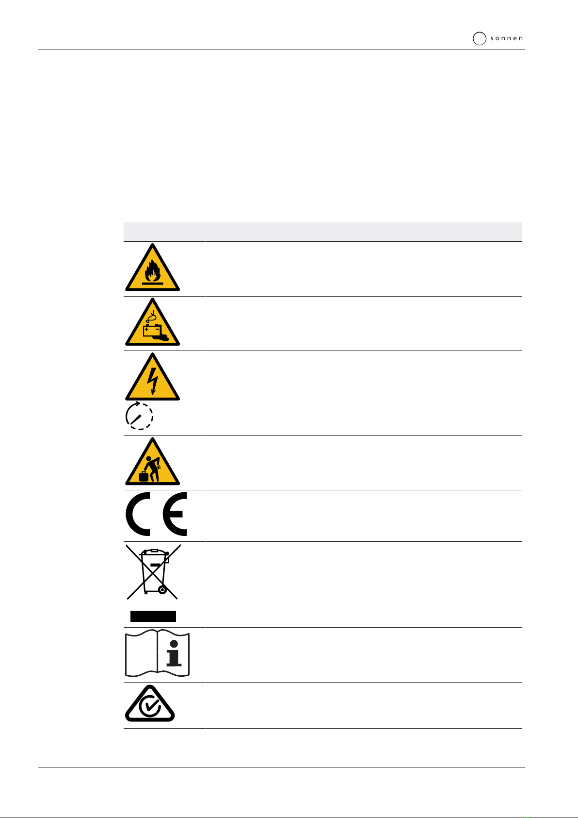
3.3 Symbols on the outside of the storage system
Symbol Meaning
Warning: flammable materials.
Warning: hazards due to batteries.
5 min
Warning: electrical voltage. Wait five minutes after switching off (capacitor de-
energising time).
kg
Warning: product is heavy.
CE mark. The product meets the requirements of the applicable EU directives.
WEEE mark. The product must not be disposed of in household waste; dispose
of it through environmentally friendly collection centres.
Observe the documentation. The documentation contains safety information.
RCM mark. The product meets the requirements of the applicable regulations.
Product description | 3
KD-564 | 1001821 | EN | 03 11 / 28
3.4 Function
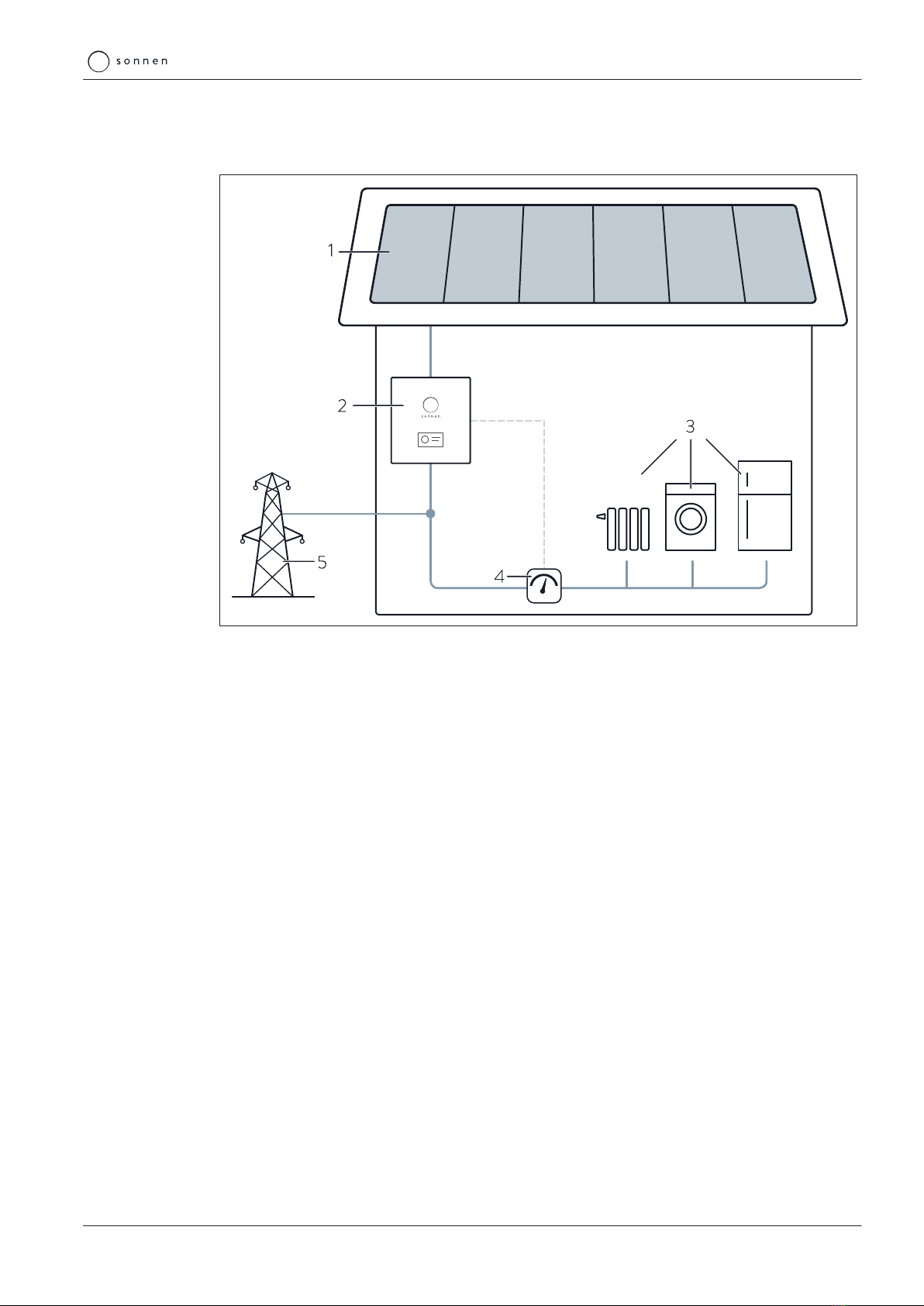
3.4.1 Basic principle
Illustration1: sonnenBatterie function
1 PV system 4 Measurement of consumption
2 Storage system 5 Public electricity grid
3 Consumers in building (e.g. washing machine,
hob, lamps, refrigerator, etc.)
The storage system (2) is connected to the PV system (1) and the public electricity grid (5).
Furthermore the current consumption of the consumers in the building (3) is constantly
measured (4).
Generation > Consumption
If the generation of power is greater than the consumption, there is a surplus of electrical
energy. In this case as much as possible of this surplus is used to charge the battery of the
storage system.
If the entire portion of the surplus can not be charged into the battery, the remaining sur-
plus is fed into the public electricity grid.
Consumption > Generation
If the consumption is greater than the generation of power, there is a deficit of electrical
energy. In this case the battery is discharged to even out as much of the deficit as possible.
If the entire deficit can not be compensated by discharging the battery, the remaining de-
ficit is covered by the public electricity grid.
3 | Product description
12 / 28 Operating instructions sonnenBatterie hybrid 9.53
3.4.2 Feed-in limit
PV systems are subject to a feed-in limit in some circumstances. The feed-in limit restricts
the PV system’s feed-in power at the mains connection point.
Example
• Nominal power of PV system: 10kWp
• Power limit: 50%
• Maximum feed-in power: 5kW
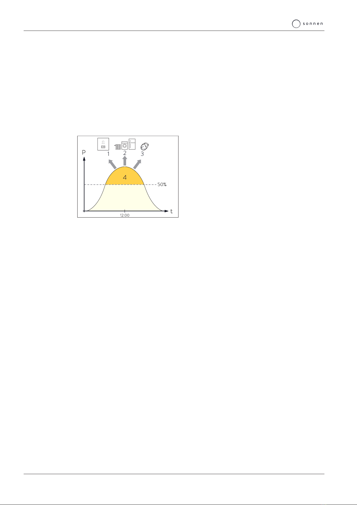
In this example, the feed-in power of 5kW must not be exceeded. The following figure
shows an example of the PV system’s production over the course of a day.
Illustration2: Example: feed-in limit at 50% of
nominal power
1 Charging of storage system
2 Switch-on of consumers via self-
consumption switch
3 Switch-on of consumers via
sonnenSmart plug
4 Midday peak, which must not be fed
into the electrical mains
To prevent production reduction – and therefore
energy loss – the excess energy is first stored in the
storage system(1) and consumption is increased by
switching on consumers(2,3). Production is only
reduced if these measures do not lead to the de-
sired limit.
Measures for limiting feed-in are explained in detail in the following. The individual meas-
ures are carried out one after the other. Only when one measure does not achieve the de-
sired reduction is the next measure introduced.
1. Charging of battery
Excess energy is directed to the storage system battery. In order for this to occur, there
must be sufficient storage capacity available in the battery.
2. Activation of the self-consumption switch
Consumers connected to the permanently wired switch output are switched on here.
3. Switch-on of consumers (via sonnenSmart plug)
The consumers are activated as soon as the feed-in limit is exceeded. The consumers are
deactivated again once the level has dropped below the limit and stayed there for at least
three minutes.
4. Reduction of PV power
Production is reduced via an integrated switch contact on the inverter. This limited the PV
inverter to a set power output. In order for this to occur, the inverter must support power
reduction using a switch contact or an external solution (e.g. a solar datalogger). Configur-
ation and connection are carried out by the electrician.
Product description | 3
KD-564 | 1001821 | EN | 03 13 / 28
3.5 Function of the sonnen Eclipse
The sonnen Eclipse (light ring in the sonnen logo on the front of the storage system) indic-
ates the current status of the storage system when it is switched on.
The following operating statuses may be indicated:
Colour Mode Operating status
White Pulsing Storage system is in normal operation.
Green Pulsing The connection to the public electricity grid is interrupted. If there is still
no connection to the public electricity grid after about five minutes, the
sonnen Eclipse switches off.
For storage systems with backup power function only*: storage system is
in backup operation.
Orange Pulsing No internet connection.
For storage systems with backup power function only*: an overload has
been detected in backup operation.
Red Constant Problem detected.
Contact the installer of the storage system or the sonnen service
team!
*Optional accessories sonnenProtect.
4 | Switching on the storage system
14 / 28 Operating instructions sonnenBatterie hybrid 9.53
4 Switching on the storage system
4.1 Switching on the PV disconnector SPV
The external PV disconnector switch establishes the connection between the PV system
and the inverter of the storage system.
Switch on the PV disconnector switch.
4.2 Switching on the fuse switch F1
NOTICE If the storage system can’t be switched on:
Do not attempt switching on the storage system more than three times.
Contact the service!
ðFurther attempts can damage the battery modules.
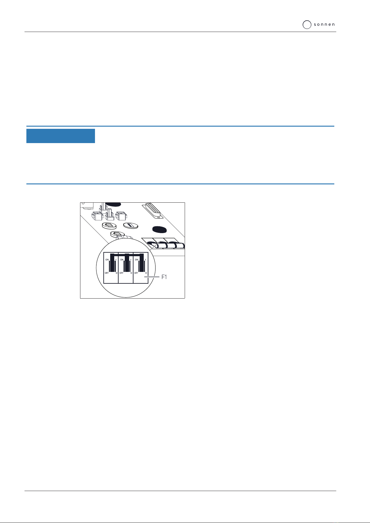
Fuse switch F1 establishes the connection between the battery and the inverter.
Illustration3: Fuse switch F1 at the top side of
the storage system
Switch on fuse switch F1.
The storage system then starts up and performs a self-test. Once the self-test is success-
ful, the storage system is ready to operate.
When the storage system is in normal operation, the sonnen Eclipse pulses white (see
Function of the sonnen Eclipse [P.13]).
4.3 Switching on the grid voltage
Switch on the grid voltage using the AC miniature circuit breaker.

Digital sonnen world | 5
KD-564 | 1001821 | EN | 03 15 / 28
5 Digital sonnen world
By purchasing the storage system you receive access to sonnen digital products. To mon-
itor the storage system and other sonnen products in real time and configure settings, you
have several options:
my.sonnen.de
You can access the online portal at any time. In addition to an overview of your products
and contracts, you will also find interesting information on the sonnenCommunity and
sonnen’s energy services.
Find out more here: Using the online portal [P.16].
find-my.sonnen-batterie.com
You can access the web interface of the storage system via a network connection. The
web interface allows you to access specific information on your storage system and adjust
settings for special functions.
The commissioning assistant, which is used by the electrician performing the installation to
configure and commission the storage system, can also be accessed here (installer’s login
required).
Find out more here: Using the web interface [P.18].

5 | Digital sonnen world
16 / 28 Operating instructions sonnenBatterie hybrid 9.53
5.1 Using the online portal
5.1.1 Logging into the online portal
To use the online portal, you need a sonnen account. If you already have a sonnen account,
you can log into the online portal directly. If not, you can create a personal sonnen account
as follows:
Enter the following address into an internet browser: my.sonnen.de
Alternatively, you can used the code here on your smartphone to access the online portal.
Scan the code with a QR reader. You can download a QR reader from the app store for
your particular device.
The login window opens.
Click on the corresponding button to register and create a sonnen account.
After creating the sonnen account you can use this in future to log in and access all sonnen
digital products.
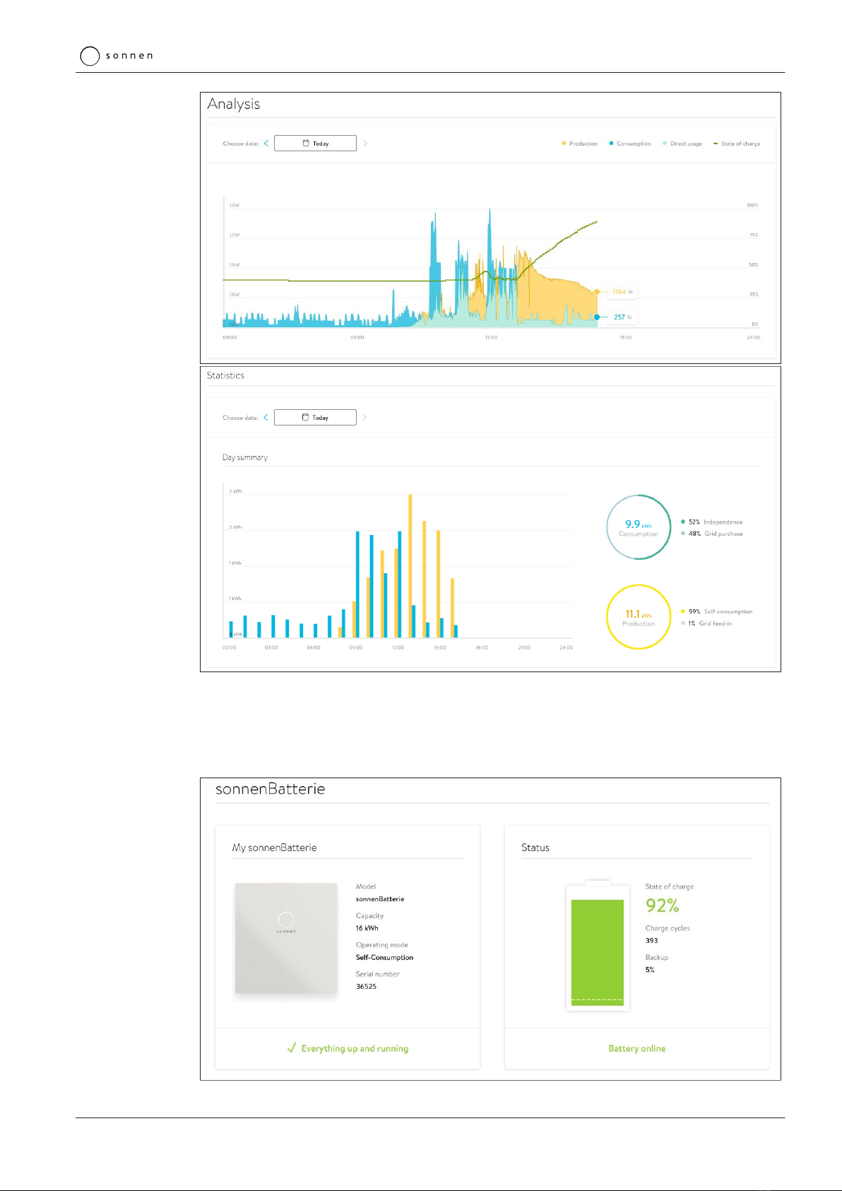
5.1.2 Visualising measurement data
A fundamental part of the online portal is the graphic display of the data from your storage
system and of processes within your building.
The Live State offers a quick overview of the cur-
rent distribution of electricity within your house-
hold. The different displays are always up-to-date
and continuously supplied with live data.
To display more details, use the Analysis page. You can easily track the activities of your
household throughout the day via the two sections Analysis and Statistics. You can also
create an overview of all recorded data on production and consumption over longer peri-
ods of time.
Digital sonnen world | 5
KD-564 | 1001821 | EN | 03 17 / 28
5.1.3 Overview of your sonnen products
You can find an overview of the current status of your sonnenBatterie and information on
your existing sonnen accessories on the pages Overview, Details and Downloads. You can
also find technical details and installation data as well documentation here.
5 | Digital sonnen world
18 / 28 Operating instructions sonnenBatterie hybrid 9.53
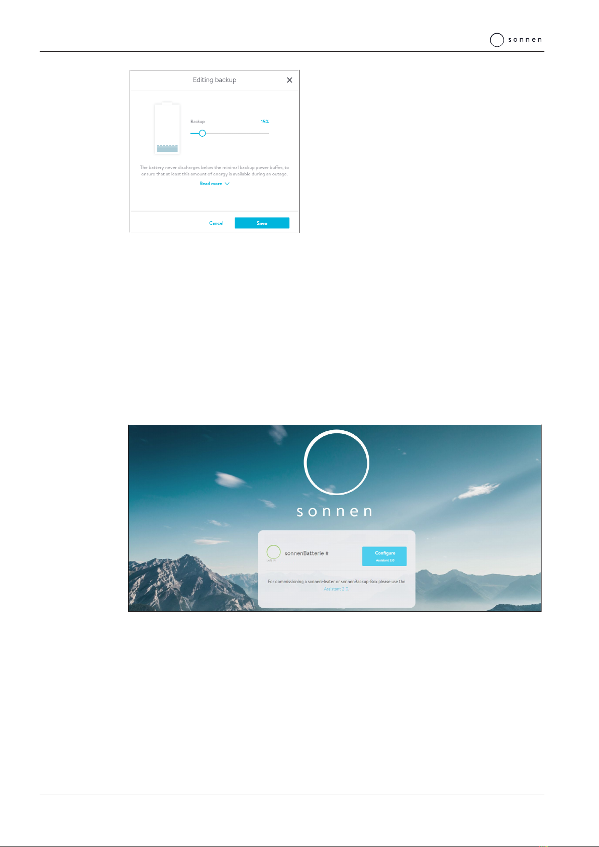
If a sonnenProtect is installed for the storage sys-
tem, click on the Overview page and set the emer-
gency buffer via the Edit button.
5.2 Using the web interface
5.2.1 Logging into the web interface
Conditions:
ü The storage system is connected to the router of the home network.
ü Your laptop or PC also accesses the home network.
ü The storage system has been set up by the electrician performing the installation using
the commissioning assistant.
Enter the following address into an internet browser:
https://find-my.sonnen-batterie.com
The following window appears:
12345
123.456.78.99
Click on the blue LAN IP number.
The login page appears.
Log in as user with the following password: sonnenUser3552

Digital sonnen world | 5
KD-564 | 1001821 | EN | 03 19 / 28
5.2.2 Dashboard page
The start page of the web interface (Dashboard) provides an initial overview of the current
status of your storage system. All of the energy flows are specified there in watts and clari-
fied with arrow indicators.
The current production of the PV system and the consumption of the electrical consumers
in the building are displayed in contrast with the storage system and the public electricity
grid. Usage from the public electricity grid is displayed when production and the electricity
available from the storage system are not sufficient to meet the energy needs of the build-
ing. Feed-in is displayed when there is sufficient electricity available to feed some into the
public grid within any existing feed-in limit.
The state of charge (SOC) of the battery modules is specified in relation to the storage
system and information as to whether the storage system is storing electricity (charging)
or providing electricity (discharging) is displayed.
5.2.3 System page
The System page provides technical background information on your storage system.
For example, you can see how many battery modules are installed (General Information >
Capacity) and what the maximum power provided by the inverters is (General Information
> Inverter Max. Power).
The other information, such as the serial number and model designation of your storage
system (each under General Information), may be necessary in the event of a fault, if you
contact the electrician performing the installation or the sonnen service team, for ex-
ample.
5.2.4 Inverter page
The Inverter page is where a self-test can be performed. This is necessary for inverters
commissioned in certain countries (including Italy).
Since this function is only required in certain regions, the test is only displayed if a corres-
ponding country code was selected for the inverter during commissioning.
5 | Digital sonnen world
20 / 28 Operating instructions sonnenBatterie hybrid 9.53
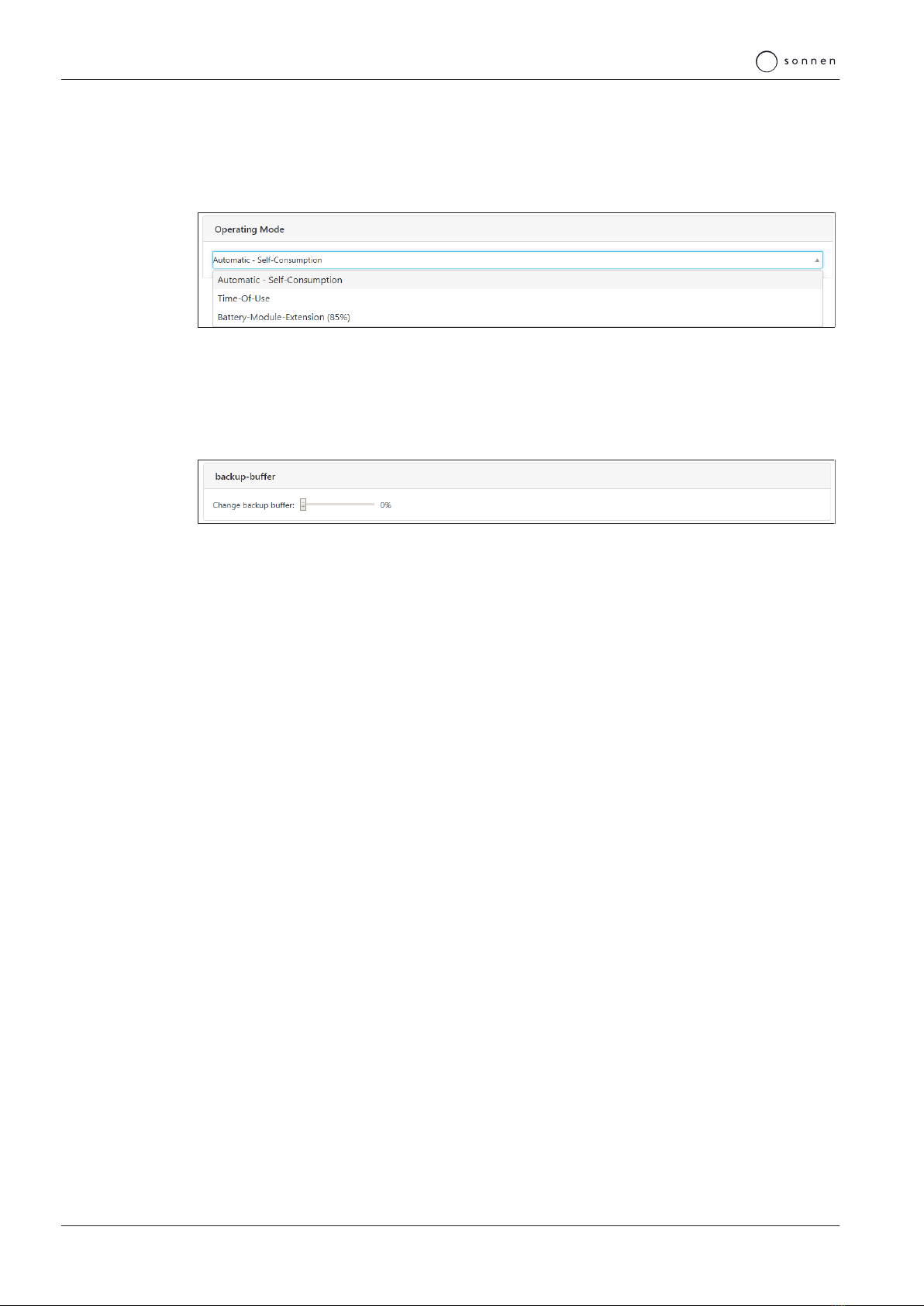
5.2.5 Settings page
Depending on the configuration of your storage system, the following areas are displayed
on the Settings page:
Operating Mode
Operating Mode Self-Consumption is normally used.
The other two operating modes (Time of Use (time linking) and Battery-Module-Extension
(30%) (module extension)) are only required in certain cases and should only be set by the
electrician performing the installation.
Backup-buffer
If a sonnenProtect is connected to the storage system, the Backup-buffer field is dis-
played. You can select the backup buffer as a percentage here. This portion of the storage
capacity is then reserved for the backup supply, i.e. this portion of the capacity is not avail-
able to the storage system in normal operation.
Combined heat and power unit (CHP)
If a CHP with constant power output is connected to the storage system and has been set
up appropriately by the installer, the Combined Heat and Power (CHP) field is displayed.
The Power specifies the constant power of the CHP and should not be changed after initial
configuration by the installer. The lower limit of the charging state at which the CHP is ac-
tivated (Charge state to start CHP) and the upper limit at which the CHP is stopped
(Charge state to stop CHP) are specified as percentages.
Contact your installer before changes are made to the settings.
Other manuals for sonnenBatterie hybrid 9.53
1
Table of contents
Other Sonnen Storage manuals

Sonnen
Sonnen sonnenBatterie ecoLinx 10 User manual

Sonnen
Sonnen sonnenEvo User manual

Sonnen
Sonnen sonnenBatterie hybrid 9.53/5 User manual

Sonnen
Sonnen sonnenBatterie eco 8.2 Manual

Sonnen
Sonnen sonnenBatterie eco 8.0 User manual

Sonnen
Sonnen sonnenBatterie eco 9.43 User manual

Sonnen
Sonnen sonnenBatterie hybrid 8.1/6 User manual

Sonnen
Sonnen eco Gen3.1 User manual

Sonnen
Sonnen eco Gen 3.1 Series Guide

Sonnen
Sonnen sonnenBatterie hybrid 9.53/5 User manual


