Sonnen sonnenBatterie hybrid 9.53/5 User manual
Installation instructions | for licensed electricians
sonnenBatterie hybrid 9.53

Publisher
sonnen GmbH
Am Riedbach 1
D-87499 Wildpoldsried
Service number +49 8304 92933 444
Email [email protected]
Document
Document number 504
Part number 22355
Version X02
Valid for AU, NZ
Publication date 16/01/2019
102254347
IMPORTANT
Read this documentation carefully before installation / operation.
Retain this document for reference purposes.
EN
Installation instructions sonnenBatterie hybrid 9.53

Table of contents
KD-504 | 22355 | EN | X02 iii
Table of contents
1 Information about this document........................................................................................................ 5
1.1 Target group of this document ................................................................................................... 5
1.2 Designations in this document .................................................................................................... 5
1.3 Explanation of symbols................................................................................................................... 5
2 Safety.............................................................................................................................................................. 6
2.1 Intended Use......................................................................................................................................6
2.2 Requirements for the electrician................................................................................................6
2.3 Operating the storage system..................................................................................................... 6
2.4 Product modifications or changes to the product environment.................................... 7
2.5 Voltage on and in the storage system....................................................................................... 7
2.6 Handling the battery modules ..................................................................................................... 7
2.7 Conduct in case of a fire................................................................................................................8
3 Product description................................................................................................................................... 9
3.1 Technical data....................................................................................................................................9
3.2 System components........................................................................................................................11
3.3 Type plate...........................................................................................................................................12
3.4 Symbols on the outside of the storage system ....................................................................12
3.5 The function of the switches.......................................................................................................13
4 Storage and transport ............................................................................................................................ 14
4.1 Storage............................................................................................................................................... 14
4.1.1 Ambient conditions during storage ............................................................................14
4.1.2 Storing the battery modules .........................................................................................14
4.2 Transport ........................................................................................................................................... 14
4.2.1 Ambient conditions during transport.........................................................................14
4.2.2 Transporting battery modules ......................................................................................14
4.2.3 Inspecting for transport damage.................................................................................15
4.2.4 Transport to the installation location ......................................................................... 17
4.2.5 Temperature adjustment after transport ................................................................. 17
5 Mounting ......................................................................................................................................................18
5.1 Scope of delivery............................................................................................................................ 18
5.2 Selecting the installation location..............................................................................................19
5.2.1 Requirements for the installation location...............................................................19
5.2.2 Observing minimum distances .....................................................................................19
5.3 Opening the storage system.......................................................................................................19
5.3.1 Opening the main cabinet..............................................................................................19
5.3.2 Removing the cover of the extension cabinet (optional)..................................20
5.4 Mounting the storage system ................................................................................................... 20
5.4.1 Requirements for mounting material.........................................................................21
5.4.2 Placing the levelling mat or the pedestal..................................................................21
5.4.3 Drilling the holes................................................................................................................21
5.4.4 Mounting the storage system......................................................................................23
6 Electrical installation...............................................................................................................................25
6.1 Working on the electrical distributor ......................................................................................25

Table of contents
iv Installation instructions sonnenBatterie hybrid 9.53
6.1.1 Placing components in the electrical distributor..................................................25
6.1.2 Wiring components in the electrical distributor ...................................................26
6.2 Connecting the power meter ....................................................................................................29
6.3 Configuring the power meter.....................................................................................................31
6.4 Connecting the mains line.......................................................................................................... 33
6.5 Connecting the ethernet line.................................................................................................... 34
6.6 Connecting the modbus line ..................................................................................................... 35
6.7 Using digital inputs/outputs....................................................................................................... 36
6.7.1 Connecting the signal line.............................................................................................36
6.7.2 Using digital output pv reduction ............................................................................... 37
6.7.3 Using digital output self-consumption switch ...................................................... 40
6.7.4 Using digital output min/max SOC .............................................................................41
6.7.5 Using digital input CHP ...................................................................................................41
6.8 Installing the battery modules................................................................................................... 43
6.8.1 Positioning and earthing the battery modules...................................................... 44
6.8.2 Connecting the BMS communication lines ............................................................46
6.8.3 Connecting the battery lines........................................................................................47
6.9 Installing covers.............................................................................................................................. 49
6.9.1 Connecting earthing conductor.................................................................................49
6.9.2 Installing the cover of the extension cabinet.........................................................49
6.10 Connecting the photovoltaic system..................................................................................... 50
6.10.1 Assembling the PV plug-in connectors....................................................................50
6.10.2 Connecting the PV system ...........................................................................................50
7 Commissioning..........................................................................................................................................52
7.1 Initial commissioning .....................................................................................................................52
7.1.1 Filling in the type plate ...................................................................................................52
7.1.2 Taking photos to document installation...................................................................52
7.1.3 Filling in the commissioning report (optional) .......................................................52
7.2 Switching on the storage system..............................................................................................52
7.2.1 Closing the storage system ..........................................................................................53
7.2.2 Switching on the grid voltage ......................................................................................53
7.2.3 Switching on the PV disconnector SPV ...................................................................53
7.2.4 Switching on the fuse switch F1 ..................................................................................53
7.3 Commissioning assistant............................................................................................................. 54
7.3.1 Establishing connection to the storage system ....................................................54
7.3.2 Running the commissioning assistant.......................................................................55
8 Decommissioning.....................................................................................................................................56
8.1 Switching the storage system off............................................................................................ 56
8.2 Switching the storage system off to electrically isolate it...............................................57
9 Troubleshooting....................................................................................................................................... 58
10 Uninstallation and disposal ...................................................................................................................59
10.1 Uninstallation................................................................................................................................... 59
10.2 Disposal............................................................................................................................................. 59
11 Installation photos .................................................................................................................................. 60
12 Commissioning report (optional) .......................................................................................................62
Information about this document | 1
KD-504 | 22355 | EN | X02 5 / 64
1 Information about this document
This document describes the installation of the sonnenBatterie hybrid 9.53.
Read this document in its entirety.
Keep this document in the vicinity of the sonnenBatterie.
1.1 Target group of this document
This document is intended for licensed electricians. The actions described here must only
be performed by licensed electricians.
1.2 Designations in this document
The following designations are used in this document:
Complete designation Designation in this document
sonnenBatterie hybrid 9.53 Storage system
1.3 Explanation of symbols
DANGER Extremely dangerous situation leading to certain death or serious injury if the
safety information is not observed.
WARNING Dangerous situation leading to potential death or serious injury if the safety
information is not observed.
CAUTION Dangerous situation leading to potential injury if the safety information is not
observed.
NOTICE Indicates actions that may cause material damage.
Important information not associated with any risks to people or property.
Symbol Meaning
►
Work step
1. 2. 3. … Work steps in a defined order
üCondition
• List
Table1: Additional symbols

2 | Safety
6 / 64 Installation instructions sonnenBatterie hybrid 9.53
2 Safety
2.1 Intended Use
The sonnenBatterie hybrid 9.53 is a battery storage system which can be used to store
electrical energy. Improper use of this system poses a risk of death or injury to the user or
third parties as well as damage to the product and other items of value. The following
points must therefore be observed in order to comply with the intended use of the prouct:
• The storage system must not be installed in any kind of combination.
• The storage system must be fully installed in accordance with the installation instruc-
tions.
• The storage system must be installed by a licensed electrician.
• The storage system is only allowed to be operated with PV generators of Class A rating
according to IEC 61730.
• The storage system must only be used at a suitable installation location.
• The transport and storage conditions must be observed.
Especially the following uses are not permissible:
• Operation in flammable environments or areas at risk of explosion.
• Operation in locations at risk of flooding.
• Operation outdoors.
• Operation of the battery modules outside of its storage system.
Failure to comply with the conditions of the warranty and the information spe-
cified in this document invalidates any warranty claims.
2.2 Requirements for the electrician
Improper installation can result in personal injury and/or damage to components. For this
reason, the storage system must only be installed and commissioned by licensed electri-
cians. Licensed electricians must meet the following criteria:
• The electrician must be a person with a technical knowledge or sufficient experience to
enable him/her to avoid dangers which electricity may create.
• The electrician must has successfully completed the sonnen Australia installer training
and have valid installer accreditation at the time of installation.
2.3 Operating the storage system
Incorrect operation can lead to injury to yourself or others and cause damage to property:
• The storage system must only be operated as described in the product documentation.
• This device can be used by children from the age of eight (8) years old and individuals
with impaired physical, sensory or mental capabilities or individuals with limited know-
ledge and/or experience of working with the device, as long as they are supervised or
have been trained to safely use the device and understand the resulting risks of doing so.
Children must not play with the device. Cleaning and user maintenance must not be car-
ried out by children without supervision.
Safety | 2
KD-504 | 22355 | EN | X02 7 / 64
2.4 Product modifications or changes to the product environment
• Only use the storage system in its original state - without any unauthorised modifica-
tions - and when it is in proper working order.
• Safety devices must never be overridden, blocker or tampered with.
• The interfaces of the storage system must be wired in accordance with the product doc-
umentation.
• An appropriate and readily accessible disconnect device shall be incorporated in the
fixed wiring.
• All repairs on the storage system must be performed by authorised service technicians
only.
• The replacement of battery modules must be performed by authorised service techni-
cians only. When replacing batteries, replace with the same type and number of batter-
ies or battery modules.
2.5 Voltage on and in the storage system
5 min
The storage system contains live electrical parts, which poses a risk of electrical shock. The
storage system inverter also contains capacitors which carry voltage even after the stor-
age system is switched off.
The PV generator of the PV system is directly connected to the storage system through
the plug-in connectors on the top side of the storage system. This means, there is voltage
present on the PV plug-in connectors when the PV system generates electricity, even if
the storage system has been switched off to electrically isolate it. Therefore:
Switch off the storage system to electrically isolate it before carrying out any work
(see Switching the storage system off to electrically isolate it [P.57]).
Only then can the storage system be opened.
2.6 Handling the battery modules
The battery modules installed in the storage system are protected by multiple protective
devices and can be operated safely. Despite their careful design, the battery cells inside
the battery modules may corrode or experience thermal runaway in the event of mechan-
ical damage, heat or a fault.
This can have the following effects:
• High heat generation on the surface of the battery cells.
• Electrolyte may escape.
• The escaping electrolyte may ignite and cause an explosive flame.
• The smoke from burning battery modules can irritate the skin, eyes and throat.
Therefore, proceed as follows:
Do not open the battery modules.
Do not mechanically damage the battery modules (pierce, deform, strip down, etc.)
Do not modify the battery modules.
Do not allow the battery modules to come into contact with water (except when extin-
guishing a fire in the storage system).

2 | Safety
8 / 64 Installation instructions sonnenBatterie hybrid 9.53
Do not heat the battery modules. Operate them only within the permissible temperat-
ure range.
Keep the battery modules well away from sources of ignition.
Do not short-circuit the battery modules. Do not allow them to come into contact with
metal.
Do not continue to use the battery modules after a short circuit.
Do not deep-discharge the battery modules.
In the event that module contents are released:
Do not enter the room under any circumstance.
Avoid contact with the escaping electrolyte.
Contact the fire services.
2.7 Conduct in case of a fire
Fire may occur with electrical equipment despite its careful design. Likewise, a fire in the
vicinity of the equipment can cause the storage system to catch fire, releasing the con-
tents of the battery modules.
In the event of a fire in the vicinity of the product or in the storage system itself, proceed
as follows:
Only firefighters with appropriate protective equipment (safety gloves, safety clothing,
face guard, breathing protection) are permitted to enter the room where the burning
storage system is located.
There is a danger of electrocution when extinguishing fire while the storage system is
switched on. Therefore, before starting to extinguish the fire:
Switch off the storage system to electrically isolate it.
Switch off the mains fuses in the building.
If the storage system and/or mains fuses cannot be safely switched off:
Observe the minimum distances specified for the extinguishing agent used. The stor-
age system works with an output voltage of 230 V (AC) and is therefore considered a
low-voltage system. However, the voltage of the PV system that is connected to the
storage system (through the PV connectors on the top of the storage system) can be
up to 750 V (DC).
• A storage system fire can be extinguished using conventional extinguishing agents.
• Water is recommended as an extinguishing agent in order to cool the battery modules
and therefore prevent thermal runaway in battery modules which are still intact.
Information on the battery modules:
• The battery modules have a nominal voltage of 48 V (DC) and therefore fall into the
range of protected extra-low voltage (under 60 V DC).
• The battery modules do not contain metallic lithium.

Product description | 3
KD-504 | 22355 | EN | X02 9 / 64
3 Product description
3.1 Technical data
sonnenBatterie hybrid 9.53/2,5 9.53/5 9.53/7,5 9.53/10 9.53/12,5 9.53/15
System data (AC)
Nominal voltage 230 V
Nominal frequency 50 Hz
Nominal power 4,600 W
Nominal current 20 A
Charging / Discharging power 1,100 W 2,500 W 3,300 W 3,300 W 3,300 W 3,300 W
Charging / Discharging current 4.8 A 10.9 A 14.3 A 14.3 A 14.3 A 14.3 A
Power factor range 0.9 cap. ... 0.9 ind.
Max. Impedance (Zmax) 0,19 Ω + j0,12 Ω
Current (Max. continous) 20 A
Max. output fault current 120 mA
Inrush current 0 A
Mains connection single-phase, L / N / PE
Max. ext. overcurrent protection 25 A, 1ph
Mains topology TN / TT
Mains connection fuse Miniature circuit breaker | Type B | 20 - 25 A
Photovoltaic (PV) input (DC)
Number of PV inputs / MPP
Tracker
2
Min. input voltage 75 V
Max. input voltage 750 V
Initial input voltage 100 V
MPP voltage range 75 V ... 600 V
Max. input power 6,500 W
Max. input current 13 A
Backfeed current to array 0 A
Short-circuit current (ISC) 15 A
Battery data (DC)
Cell technology lithium iron phosphate (LiFePO4)
Max. capacity 2.5 kWh 5.0 kWh 7.5 kWh 10.0 kWh 12.5 kWh 15.0 kWh
Usable capacity 2.25 kWh 4.5 kWh 6.75 kWh 9.0 kWh 11.25 kWh 13.5 kWh
Nominal voltage 48 V
Current (Max. continous) 75 A
Short-circuit current(ISC) 90 A
Min. number of battery modules 1

3 | Product description
10 / 64 Installation instructions sonnenBatterie hybrid 9.53
Max. number of battery modules 6
Dimensions / weight without extension cabinet (from 2.5 up to 5 kWh)
Dimensions (H/W/D) in cm 88/67/23 - - - -
Weight in kg 58 81 - - - -
Dimensions / weight with small extension cabinet (from 2.5 up to 10 kWh)
Dimensions (H/W/D) in cm 137/67/23 - -
Weight in kg 74 97 120 143 - -
Dimensions / weight with big extension cabinet (from 2.5 up to 15 kWh)
Dimensions (H/W/D) in cm 186/67/23
Weight in kg 85 108 131 154 154 200
Safety
Protection class I / PE conductor
Required fault current monitoring Residual current device (RCD) | Type B | 30 mA
Degree of Protection IP30
Rated short-withstand cur-
rent(ICW)
10 kA
Separation principle PV -> AC no galvanic isolation, transformer-less
Separation principle Batt. -> AC galvanic isolation (functional insulation)
Power meter
Voltage measurement inputs Nominal voltage (AC): 230 V (L-N), 400 V (L-L) | max. connectible conductor
cross-section: 1.5 mm²
Clamp-on current transformer Max. measurable current: 60 A (standard), optional up to 400 A
Ambient conditions
Environment Indoor (conditional)
Ambient temperature range1-5 °C ... 45 °C
Storage temperature range 0 °C ... 40 °C
Transport temperature range -15 °C ... 50 °C
Max. rel. humidity 90 %, non-condensing
Permissible installation altitude 2,000 m above sea level
Pollution degree 2
Additional ambient conditions:
• The installation location must not be at risk of flooding.
• Installation room should be ventilated.
• The currently applicable building codes must be observed.
• Even floor, suitable for heavy loads.
• Observe fire control standards.
• Free from corrosive and explosive gases (ammonia content max. 20 ppm).
• Free from dust (especially flour dust or sawdust).
• Free from vibrations.
1 Optimal: 5 °C … 30 °C | Derating possible below 5 °C / above 30 °C.
Product description | 3
KD-504 | 22355 | EN | X02 11 / 64
• Free access to the installation location.
• No direct sunlight.
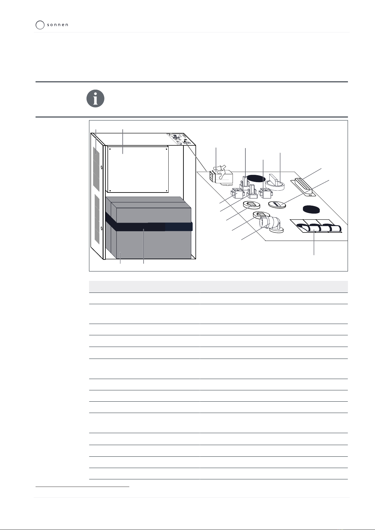
3.2 System components
The inverter of the storage system is retrofittable for the connection of an ex-
ternal Demand Response Enabling Device (DRED)2 in order to support De-
mand Response Mode Zero (DRM 0).
XDIO
XAC
XSO3
XSO2
XSO1
F1
SPV
XPV2M
XPV2P
3
2
XPV1P
1
4
XPV1M
XSO4
Illustration1: System components of the storage system
No. Designation Function
1 Filter plate Holder for filter pad.
2 Inverter Conversion of batteries’ direct current into alternating
current.
3 Battery module(s) Storage of electrical power.
4 Securing band Fixation of the battery modules.
F1 Fuse switch F1 On / Off switch of the storage system.
SPV PV disconnector Switch to isolate all poles of the DC connection
between the photovoltaic system and the inverter.
XPV1P 1st PV plus connection Connection to the first plus wire from the pv system.
XPV1M 1st PV minus connection Connection to the first minus wire from the pv system.
XPV2P 2nd PV plus connection Connection to the second plus wire from the pv system.
XPV2M 2nd PV minus connection Connection to the second minus wire from the pv sys-
tem.
XAC Mains connection Connection to the public electrical grid.
XDIO Digital inputs and outputs Interface to emit and receive digital signals.
XSO1 USB port Port for connection of an Z-Wave USB stick.
XSO2 Modbus port Data connection to power meter.
2 Set ‘Retrofitting DRED port’ is available from sonnen GmbH.

3 | Product description
12 / 64 Installation instructions sonnenBatterie hybrid 9.53
XSO3 Ethernet port Data connection to router for home network.
XSO4 Emergency power Connection to sonnenProtect (optional accessories).
3.3 Type plate
The type plate for the storage system is located on the outer surface of the system. The
type plate can be used to uniquely identify the storage system. The information on the type
plate is required for the safe use of the system and for service matters.
The following information is specified on the type plate:
• Item designation
• Item number
• Technical data of the storage system
The battery capacity and the nominal power of the storage system differ depending on the
number of battery modules installed. For this reason the installed battery capacity must be
ticked on the type plate by the electrician installing the system (see Filling in the type plate
[P.52]).
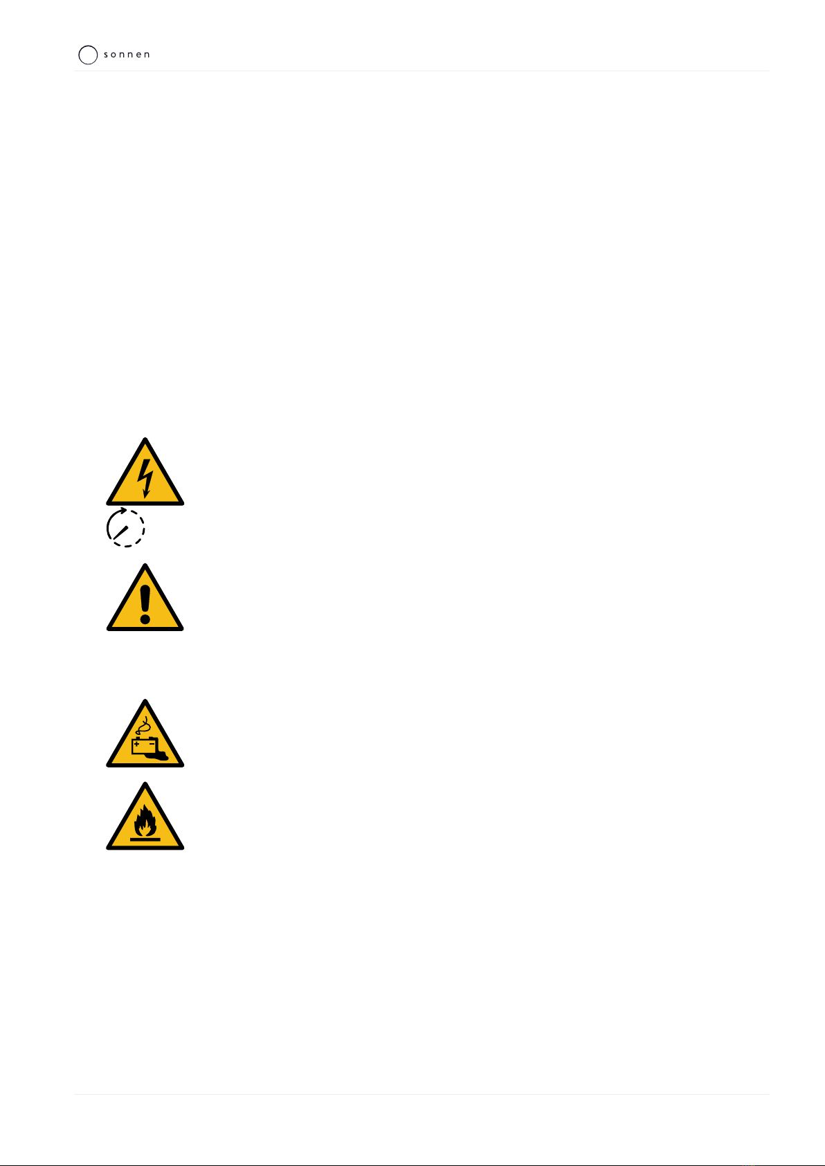
3.4 Symbols on the outside of the storage system
Symbol Meaning
Warning: flammable materials.
Warning: hazards due to batteries.
Warning: electrical voltage.
5 min
Warning: electrical voltage. Wait five minutes after switching off (capacitor
de-energising time).
Warning: Equipment with multiple sources of supply (PV generator, AC mains
and battery).
kg
Warning: product is heavy.
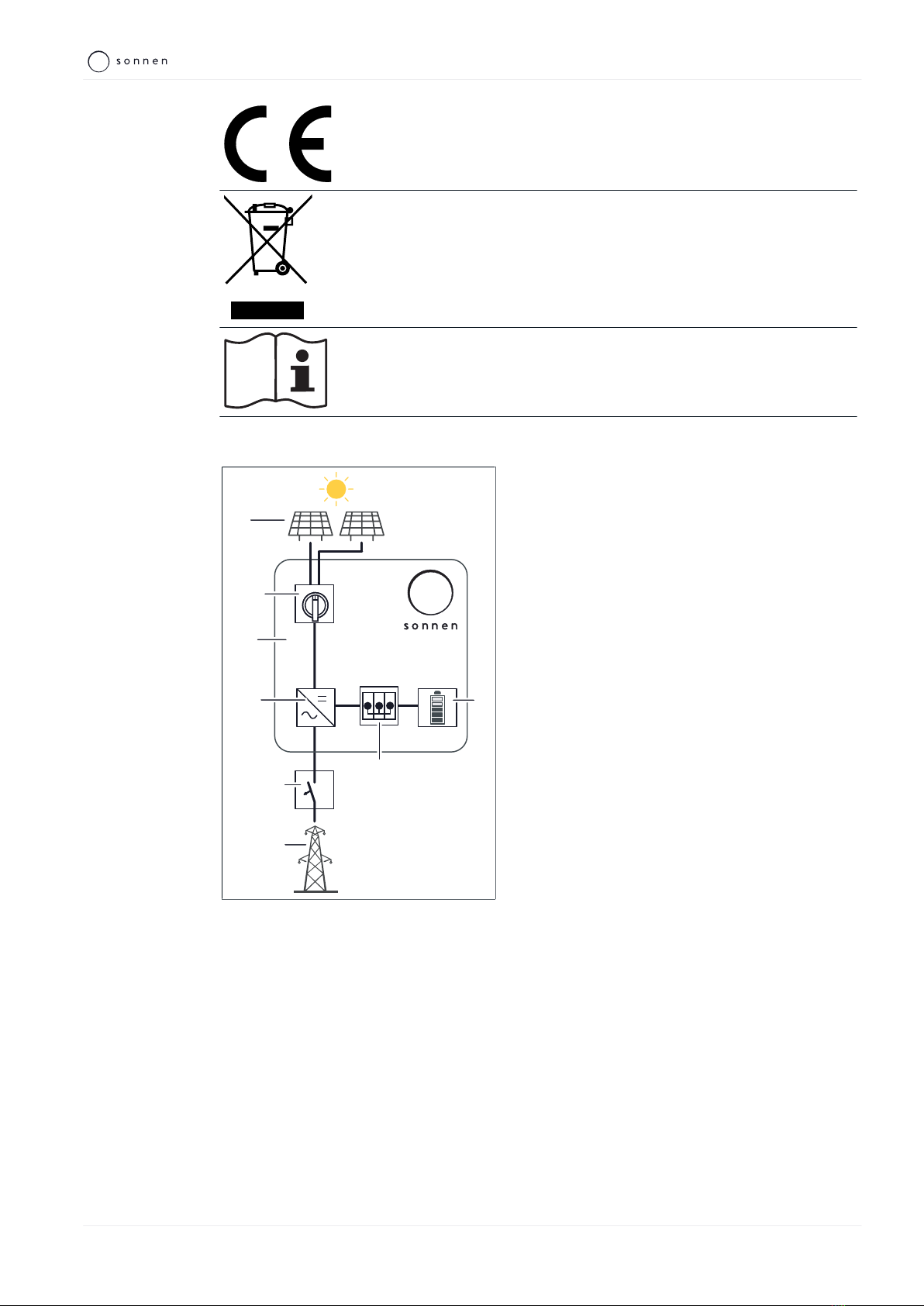
Product description | 3
KD-504 | 22355 | EN | X02 13 / 64
CE mark. The product meets the requirements of the applicable EU directives.
WEEE mark. The product must not be disposed of in household waste; dispose
of it through environmentally friendly collection centres.
Observe the documentation. The documentation contains safety information.
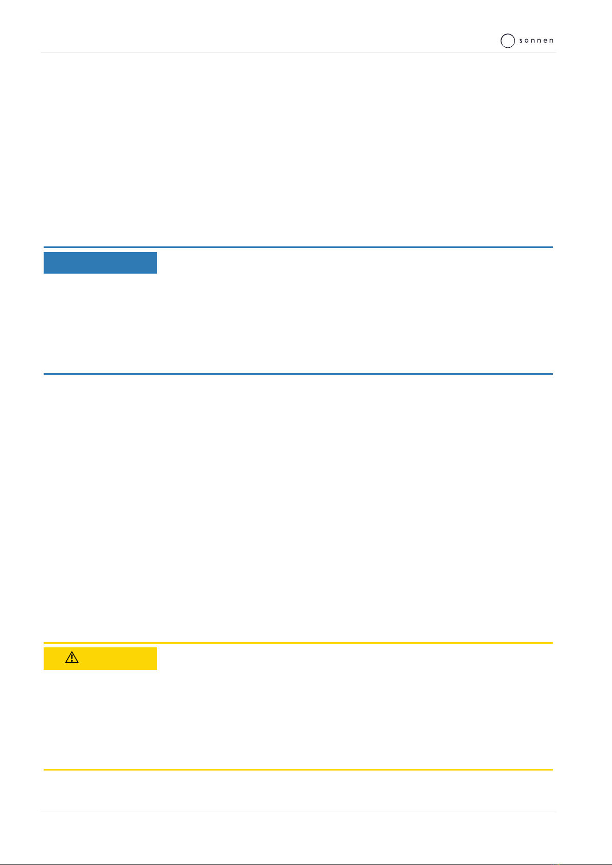
3.5 The function of the switches
F1
SPV
2
6
3
1
5
I
0
off off off
4
Illustration2: Block diagram of the switching ele-
ments
1 PV system
2 Storage system
3 Inverter
4 AC circuit breaker
5 Mains connection
6 Battery
F1 Fuse switch
SPV PV disconnector
PV disconnector (SPV)
The PV disconnector (SPV) is in the DC circuit
between the PV system (1) and the inverter (3).
In switch setting I the PV system and the inverter
are connected together. In switch setting 0 the
PV system and the inverter are isolated from one
another on all poles.
Fuse switch F1
The fuse switch F1 is in the DC circuit between
the battery (6) and the inverter (3).
In switch setting ON the battery and the inverter
are connected together. In switch setting OFF
the battery and the inverter are isolated from
one another.
AC circuit breaker
The circuit breaker (4) is in the AC circuit
between the public electricity network (5) and
the storage system (2).
4 | Storage and transport
14 / 64 Installation instructions sonnenBatterie hybrid 9.53
4 Storage and transport
4.1 Storage
Storage describes the condition when the storage system is not connected to the public
electrical mains and the battery modules cannot be automatically charged.
4.1.1 Ambient conditions during storage
The ambient conditions specified in section Technical data [P.9] must be observed during
storage.
4.1.2 Storing the battery modules
NOTICE Deep-discharge of the battery modules
Destruction of the battery modules!
Do not disconnect the storage system from the public grid for long periods
of time.
Never continue to operate battery modules which have been deep-dis-
charged.
During storage the battery modules automatically discharge at a minimal level. Deep-dis-
charge could damage or destroy the battery modules. For this reason, the battery modules
can only be stored for a limited amount of time.
Observe the following points:
• The battery modules must be charged to 60 % (charging status upon delivery) when
stored.
• Store the battery modules for no longer than 6 months.
• Install the battery modules in the storage system after 6 months at the most and com-
mission the storage system.
4.2 Transport
4.2.1 Ambient conditions during transport
The ambient conditions specified in section Technical data [P.9] must be observed during
transport.
4.2.2 Transporting battery modules
CAUTION Improper transport of battery modules
Fire outbreak at battery modules or emission of toxic substances!
Transport the battery modules in their original packaging only. If you no
longer have the original packaging, new packaging can be requested from
sonnen GmbH.
Never transport damaged battery modules.
Lithium-ion batteries are hazardous goods. Therefore the following points must be ob-
served when transporting the battery modules:
Storage and transport | 4
KD-504 | 22355 | EN | X02 15 / 64
Observe the general transport regulations based on the mode of transport as well as all
legal regulations.
Consult an external hazardous goods expert.
Hazardous goods class UN number Battery module mass
9 UN 3480 ‘lithium-ion batteries’ 24 kg (incl. packaging)
Table2: Battery module data relevant for transport
4.2.3 Inspecting for transport damage
CAUTION Use of damaged battery modules
Fire outbreak at battery modules or emission of toxic substances!
Unpack the battery modules immediately after transport and inspect them
for transport damage.
Check the temperature indicator on the back of the battery module.
ðIf the temperature indicator turned red or
ðif damage (deformation, damage to the housing, emission of substances
and the like) is discovered:
Do not use the battery modules under any circumstance.
Notify the service team.
CAUTION Insulation fault when storage system is damaged
Danger of electric shock when touching damaged insulation elements!
Unpack the storage system immediately after transport and inspect it for
transport damage.
Do not use a damaged storage system under any circumstance.
The shipping company can only be held liable for transport damage if it can be proven that
the damage occurred during the course of transport. For this reason it is important to fol-
low the instructions given here as closely as possible.
Transport damage is divided into open and hidden damage. Open damage is externally vis-
ible damage to the transported goods or their packaging. Hidden damage occurs when the
packaging is not damaged but the transported goods inside are.
Open transport damage must be reported to the shipping company immediately. The fol-
lowing time frames apply in the case of hidden transport damage:
• Deutsche Post / DHL / parcel services: report damage within 24 hours
• Shipping company: report damage within 7 days
Proceed as follows:
1. Check the shipping documents
Check the recipient address and numbers of shipped goods in the presence of the
shipper.
4 | Storage and transport
16 / 64 Installation instructions sonnenBatterie hybrid 9.53
2. Inspect the goods for open damage
Inspect the packaging and transport goods for external damage in the presence of the
shipper.
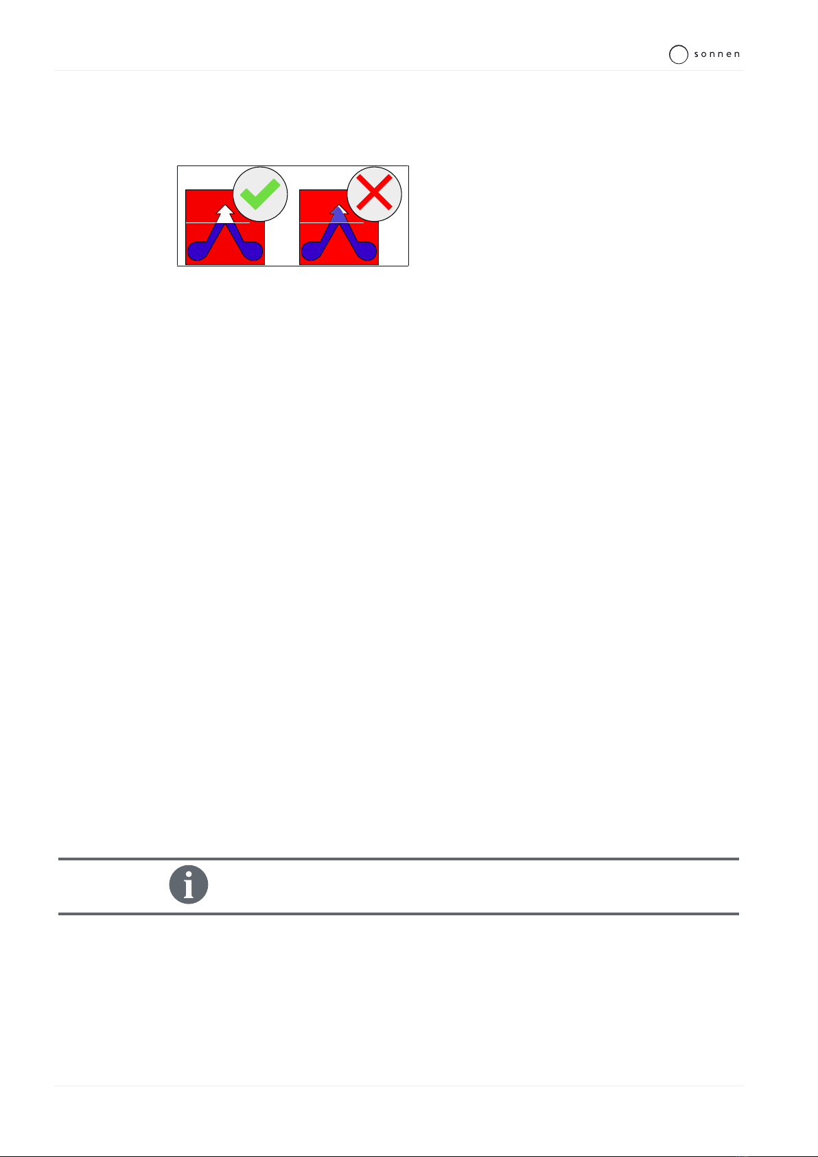
Illustration3: Transport indicator affixed to the
packaging
Check the transport indicator affixed to the
packaging of the main cabinet in the presence
of the shipper.
The storage system has not been transported properly if blue powder has been transferred
into the arrow of the transport indicator.
Refuse to accept the goods if blue powder has been transferred into the arrow of the
transport indicator.
3. Inspect the goods for hidden damage
This inspection should also take place in the presence of the shipper if possible.
Unpack the goods.
Inspect the goods for hidden (not immediately visible) transport damage.
If transport damage is discovered:
Stop unpacking the product.
Collect photographic evidence of the damage.
Refuse to accept the goods if the discovered defects are serious.
4. Document the defects
Document the defects identified on the consignment note.
Additionally, document the following:
• Notation ‘Conditional acceptance’.
• Registration number of the delivery vehicle.
• Signature of the shipper.
5. Report the damage
Report the damage to the responsible transport company and the manufacturer imme-
diately.
Send the consignment note/delivery note with the shipper's confirmation of the dam-
age and photographic evidence to the manufacturer by email.
Damage claims cannot be settled if the above mentioned documentation is not
submitted within the stated reporting time frames.
Storage and transport | 4
KD-504 | 22355 | EN | X02 17 / 64
4.2.4 Transport to the installation location
WARNING High weight of the storage system
Risk of injury by lifting/dropping the storage system!
Wear safety footwear when setting up.
Ensure a secure footing.
At least two people are necessary to carry the main cabinet of the storage
system.
4.2.5 Temperature adjustment after transport
NOTICE Forming of condensation
Damage to the storage system!
Check the inside of the storage system for condensation before installation.
Only install the storage system if there is no condensation on the surfaces.
If the temperature of the storage system is lower than the ambient temperature of the
room when it is delivered, condensation may form inside the storage system.
If the storage system has been transported in sub-zero temperatures, proceed as follows:
1. Set up the storage system in a suitable location.
2. Open all main cabinet doors.
3. Leave the storage system to stand for at least 24 hours with open main cabinet doors.
4. Only then can you commission the storage system.
5 | Mounting
18 / 64 Installation instructions sonnenBatterie hybrid 9.53
5 Mounting
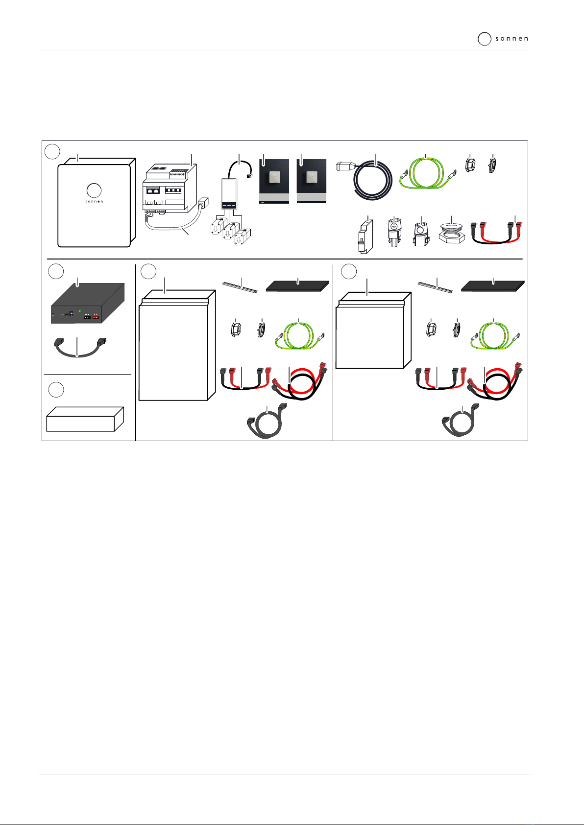
5.1 Scope of delivery
Check the following scope of delivery to ensure it is complete.
_+
14 13
A
B
E
8 9 10
11
KL
KL
KL
1 2 3
KSW 1x
1x
1x
1x
+49 (0) 8304 / 92933 - 444 · info@sonnenbatte rie.de · www.sonnenbatterie.de
+49 (0) 8304 / 92933 - 444 · info@sonnenbatte rie.de · www.sonnenbatterie.de
1x
1x
146
5
1
2
7
1x
3
C
1x
1x
D
E
POWER
LINK-IN
LINK-OUT
CONTROLLER
RS232
STATUSPOWER
2x
2
7
2x
4x
9
6
2x 2x 2x
1x
12
2x
2x
15
1x
4 5
6x 6x
8
3
1x
1x
2
7
2x
2x
9
6
1x
4 5
4x 4x
8
2x 1x
2x
2x
1x
1x
2
3
A1 A2 13 14 15 16
1x
11
1x
A For main cabinet B For battery module D For small extension cabinet
1 Main cabinet 1 Battery module 1 Small extension cabinet
2 Power meter WM271 2 BMS communication line, short 2 Edge protection
3 Modbus line with RJ-45 coupling C For big extension cabinet 3 Levelling mat
4 Current transformer KSW 60-3 1 Big extension cabinet 4 Locking nut
5 Operating instructions 2 Edge protection 5 Contact disc
6 Installation instructions 3 Levelling mat 6 Earthing lines
7 Mains line 4 Locking nut 7 Battery lines, short
8 Earthing line 5 Contact disc 8 Battery lines, long
9 Locking nut 6 Earthing lines 9 BMS communication line, long
10 Contact disc 7 Battery lines, short EPedestal for extension cabinet (optional)
11 Battery lines, short 8 Battery lines, long
12 Blanking plug with locknut 9 BMS communication line, long
13 PV plug-in connector minus
14 PV plug-in connector plus
15 Miniature circuit breaker B20
Mounting | 5
KD-504 | 22355 | EN | X02 19 / 64
5.2 Selecting the installation location
5.2.1 Requirements for the installation location
Observe the required ambient conditions (see Technical data [P.9]).
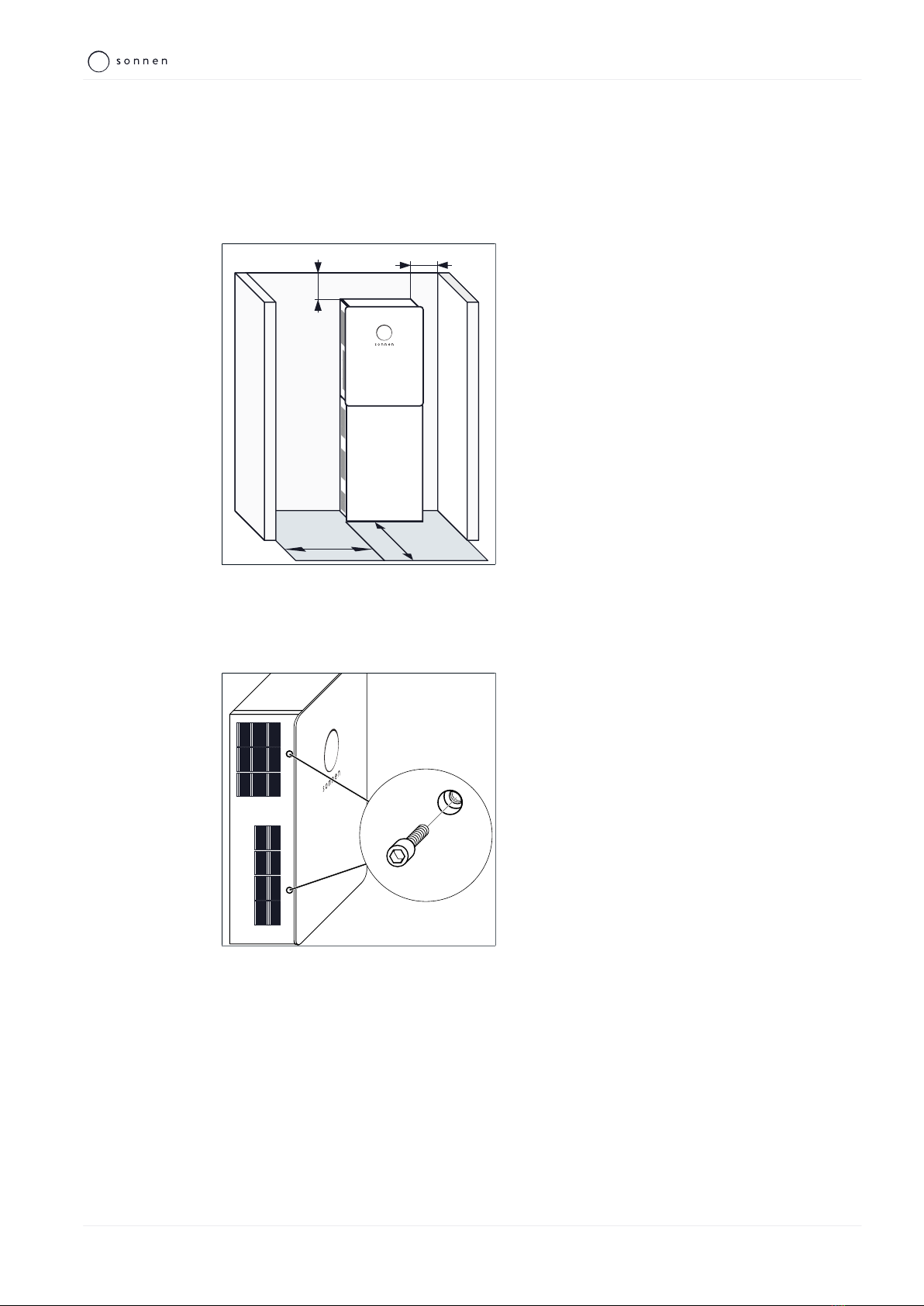
5.2.2 Observing minimum distances
50 cm 100 cm
5 cm
15 cm
Illustration4: Minimum distances
Observe the specified minimum distances to
neighbouring objects.
The minimum distances ensure that:
• there is sufficient heat dissipation,
• the storage system door can be opened easily
and
• there is sufficient space for maintenance work.
5.3 Opening the storage system
5.3.1 Opening the main cabinet
Illustration5: Opening the door of the main cab-
inet
Remove the two Allen screws on the left side
of the main cabinet.
Open the door of the main cabinet.
5 | Mounting
20 / 64 Installation instructions sonnenBatterie hybrid 9.53
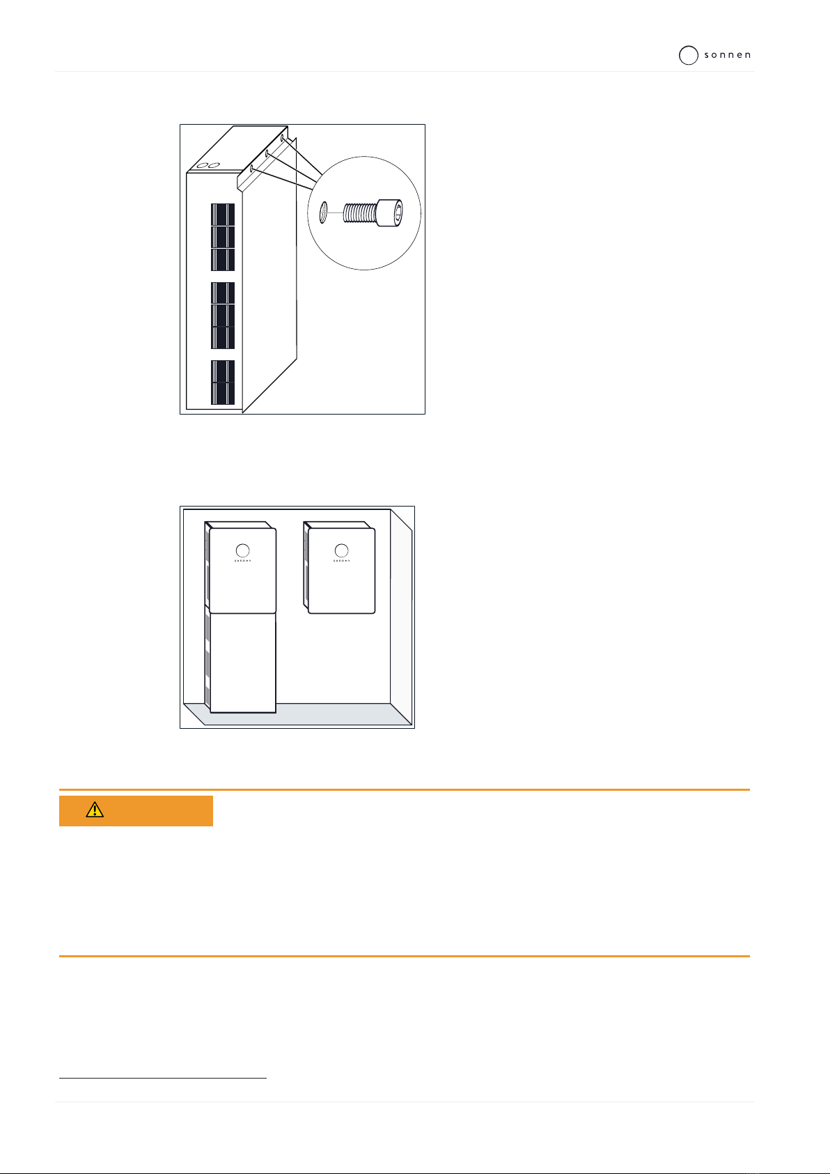
5.3.2 Removing the cover of the extension cabinet (optional)
Illustration6: Removing the cover of the exten-
sion cabinet
To remove the cover of the extension cabinet:
Remove the three screws.
Slide the cover up.
5.4 Mounting the storage system
Illustration7: Storage system with optional ex-
tension cabinet (floor mounted) / Storage sys-
tem without extension cabinet (wall mounted)
• A storage system without the optional extension
cabinet must be mounted to the wall with screws.
• A storage system with the extension cabinet
must be floor mounted.
WARNING Inadequate protection against contact if installed without base cabinet
Risk of injury from contact with the battery modules through the openings in
the floor of the main cabinet!
Ensure that both openings in the floor of the main cabinet are sealed with
the provided blanking plugs on the inside and the locknuts on the outside of
the storage systems.
Permissible blanking plugs3 must meet the following requirements:
• Material: metal or plastic with a flammability class of V-1 in accordance with UL94
• Fine thread: M32x1,5
• External diameter: 35 mm
3 Additional blanking plugs and nuts are available from sonnen GmbH.
Other manuals for sonnenBatterie hybrid 9.53/5
1
This manual suits for next models
6
Table of contents
Other Sonnen Storage manuals

Sonnen
Sonnen sonnenBatterie 10 User manual

Sonnen
Sonnen sonnenBatterie hybrid 9.53/5 User manual

Sonnen
Sonnen eco Gen 3.1 Series Guide

Sonnen
Sonnen sonnenBatterie Evo User manual

Sonnen
Sonnen sonnenEvo User manual

Sonnen
Sonnen eco Gen3.1 User manual

Sonnen
Sonnen sonnenBatterie eco 8.0 User manual

Sonnen
Sonnen sonnenBatterie eco 8.2 Manual

Sonnen
Sonnen sonnenBatterie hybrid 8.1/6 User manual

Sonnen
Sonnen sonnenBatterie hybrid 9.53 User manual


