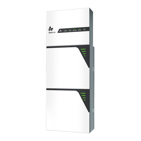
Sonnen eco Gen 3.1 Series Guide

Installation and commissioning manual
sonnen eco Gen 3.1
eco

installation and
commissioning
manual
Page intentionally left blank

This manual refers to:
Product: eco Gen3.1
Latest revision: 08/2019
Version: 1.0
If you need help or service, contact sonnen Service Line at
1 (818) 824-6363 Monday-Friday 8AM-8PM EST,
Copyright
This publication, including all photographs, illustrations and
software, is protected under international copyright laws, with
all rights reserved. Neither this manual, nor any of the material
contained herein, may be reproduced without written consent of the
author.
© Copyright 2019
Disclaimer
The information in this document is subject to change without
notice. The manufacturer makes no representations or warranties
with respect to the contents hereof and specifically disclaims any
implied warranties of merchantability or fitness for any particular
purpose. The manufacturer reserves the right to revise this
publication and to make changes in the content hereof without
obligation of the manufacturer to notify any person of such revision
or changes.

Page intentionally left blank

Contents
About this manual 1
Target audience ..............................................1
Terminology.....................................................1
Symbols used...................................................1
Safety 2
Intended use ..................................................2
Prohibited uses ..............................................2
General warnings ..........................................2
General safety instructions..........................2
Fire-related instructions...............................3
Battery module information ....................... 4
Specifications 5
Dimensions Storage system dimensions.................6
Key components .........................................6
Storage and transport 7
Storing the system ........................................7
Transporting the system...............................7
Installation 9
Tools needed ..................................................9
Clearance requirements .............................9
Inspecting the storage system ..................10
Mounting the storage system....................10
Electrical connections 15
The LFP2 battery module........................... 16
The Hub board ..............................................17
Connecting AC cables .................................17
Generator Autostart wiring (optional) ..... 21
Emergency stop switch (optional) ........... 22
Emergency stop wiring (optional)............ 22
Connecting PV Production Meter........... 23
Installing battery modules......................... 24
Commissioning checklist...........................30
Commissioning 32
Turn on the storage system....................... 32
Commissioning assistant ........................... 33
Digital interface 38
Internet portal ............................................ 38
Establish connection to the Internet....... 38
Internet portal ............................................ 38
Direct access to the storage unit............. 42
Decommissioning 45
Shutting the storage system down.......... 45
Recycling and certificates......................... 45
Maintenance and care 47
Function control ........................................ 47
Care of the storage system ...................... 47
Appendix 1. Nameplates and labels 48
Appendix 2. Glossary 50
Appendix 3. Warranty 52

Figures
Fig. 1 Power LED..........................................................................3
Fig. 2 ecoLinxX key components ..............................................6
Fig. 3 Allowed tilt positions....................................................... 8
Fig. 4 Clearance requirements..................................................9
Fig. 5 Multiple unit clearance requirements ...........................9
Fig. 6 Mounting cleat................................................................10
Fig. 7 Mounting cleat location.................................................10
Fig. 8 Positioning the mounting bracket................................. 11
Fig. 9 Sliding the cabinet into the mounting cleat ................ 11
Fig. 10 Securing the mounting cleat ....................................... 11
Fig. 11 Unlocking the door ......................................................... 11
Fig. 12 Removing the dead front.............................................. 11
Fig. 13 Connecting cabinets (left side)................................... 12
Fig. 14 Connecting cabinets (right side) ................................ 12
Fig. 15 Removing the cabinet cover........................................ 12
Fig. 16 Installing edge protectors............................................ 12
Fig. 17 Flat band grounding...................................................... 13
Fig. 18 Conduit dimensions ...................................................... 13
Fig. 19 Conduit MAX exterior dimensions ............................. 13
Fig. 20 Conduit entry location (top view) ............................. 13
Fig. 21 Removing battery cabinet access panel cover .........14
Fig. 22 LFP2 battery module main components................... 16
Fig. 23 Hub board...................................................................... 17
Fig. 24 Installation using protected loads panel ................... 17
Fig. 25 Installation without protected loads panel............... 17
Fig. 26 Stripping cable.............................................................. 18
Fig. 27 Automatic transfer switch actuator........................... 18
Fig. 28 Micro-grid connections location ............................... 19
Fig. 29 Micro-grid connections............................................... 19
Fig. 30 Grid connections location .......................................... 19
Fig. 31 Grid connections........................................................... 19
Fig. 32 Grounding connections location...............................20
Fig. 33 Grounding connections.............................................. 20
Fig. 34 Generator AC connections .......................................20
Fig. 35 Ethernet socket location............................................. 21
Fig. 36 12V signal connection.................................................. 21
Fig. 37 24V signal connection ................................................. 21
Fig. 38 Dry Contact signal connection ................................. 22
Fig. 39 J1 J2 Hub board jumper pins...................................... 22
Fig. 40 Emergency stop connection..................................... 22
Fig. 41 Current transformer markings................................... 23
Fig. 42 Current transformers S1 and S2................................ 23
Fig. 43 Battery Terminal covers ............................................. 24
Fig. 44 Labeling battery modules .......................................... 24
Fig. 45 Battery module placement........................................ 24
Fig. 46 Battery module configurations................................. 25
Fig. 47 Securing battery modules.......................................... 25
Fig. 48 Place topside mounting bracket............................... 25
Fig. 49 Secure topside mounting bracket ............................ 25
Fig. 50 Secure battery modules............................................. 25
Fig. 51 Inserting set screws ..................................................... 26
Fig. 52 2 battery bus bar arrangement ................................. 26
Fig. 53 3 battery bus bar arrangement ................................. 26
Fig. 54 4 battery bus bar configuration.................................27
Fig. 55 Terminal spacer.............................................................27
Fig. 56 Installing power jumper cables.................................. 28
Fig. 57 Connect power homerun cables............................... 28
Fig. 58 Installing flange nuts................................................... 29
Fig. 59 Connecting BMS communication cables................. 29
Fig. 60 Link-IN to Link-OUT daisy-chain............................... 29
Fig. 61 Reinstall access panel ................................................... 31
Fig. 62 Re-install dead front panel.......................................... 31
Fig. 63 Turning on battery modules....................................... 32
Fig. 64 Pre-charge switch and circuit breaker..................... 32
Fig. 65 Identifying the storage system ................................. 33
Fig. 66 Logging in to the storage system ............................. 33
Fig. 67 Installing system updates ........................................... 33
Fig. 68 Setting installation location....................................... 33
Fig. 69 Verifying the date and time ....................................... 33
Fig. 70 Entering PV system information............................... 34
Fig. 71 Generator Autostart information .............................. 34
Fig. 72 Time of Use information............................................. 34
Fig. 73 Configuring Micro-grid "wake-up" times ................. 35
Fig. 74 Configuring meters..................................................... 35
Fig. 75 Inputting owner information ..................................... 36
Fig. 76 Providing information about installer....................... 36
Fig. 77 Selecting Operating Mode......................................... 36
Fig. 78 Login window ............................................................... 38
Fig. 79 Portal overview screen............................................... 39
Fig. 80 Status view................................................................... 39
Fig. 81 History view ..................................................................40
Fig. 82 History view overlays..................................................40
Fig. 83 History view week view..............................................40
Fig. 84 Specific data history....................................................41
Fig. 85 Typical history graph.................................................... 41
Fig. 86 Typical history graph values........................................ 41
Fig. 87 Storage unit configure................................................ 42
Fig. 88 Storage unit dashboard.............................................. 42
Fig. 89 Operating mode settings........................................... 42
Fig. 90 Backup buffer.............................................................. 43
Fig. 91 Grid enable option ....................................................... 43
Fig. 92 Re-enable microgrid................................................... 43
Fig. 93 System information ....................................................44
Fig. 94 F1 circuit breaker......................................................... 45

Tables
Table 1 Specifications ..................................................................5
Table 2 Conduit entries and cable sizes.................................. 13
Table 3 Commissioning prerequisites....................................30
Table 4 Required open ports for storage system ................ 38

Page intentionally left blank

1
About this manual
This manual describes the installation and
operation of the sonnen eco Gen 3.1 storage
system. Read this manual carefully before
beginning work and keep it near the storage
system.
Target audience
This document is intended for the following
audiences:
• Installer of the storage system
• Trained and certified electrician
Some actions described in this document must
only be performed by a trained and certified
electrician. These actions are marked as follows:
Trained, electrically qualified person only!
Trained, electrically qualified persons are:
• Service partners authorized by sonnen Inc.
• Trained, electrically qualified persons with
knowledge of all applicable regulations and
standards.
• Trained, electrically qualified persons who have
attended the training provided by sonnen.
Terminology
This document refers to the sonnen eco Gen 3.1
as a storage system.
This manual refers to the building being serviced
by the storage system as a “house,” but the sonnen
eco Gen 3.1 can be installed in any number of
buildings or sites powered by AC electricity.
For a full glossary of terms used in this manual,
refer to Appendix 2.
Symbols used
Warnings
WARNING WORD
Warnings are indicated by this
symbol and a warning word, which
indicates the severity of the
danger. Along with the warning
are instructions for avoiding the
danger.
The following warning words are used:
• ATTENTION indicates possible material
damages.
• CAUTION indicates a possible hazardous
situation which could result in minor or
moderate injury.
• WARNING indicates a possible hazardous
situation which could result in death or serious
injury.
• DANGER indicates an imminent hazardous
situation which will result in death or serious
injury.
Important information
Important information without danger
to injury, death, or material damage is
indicated by this symbol.
Actions
Actions to be taken are marked with a ▶. For
example:
▶Read this manual thoroughly before operating
the storage unit.
Electrical symbols
Indicates protective earth (ground).
Nindicates the connection for the neutral
conductor on permanently installed equipment.

2
Safety
Intended use
Any use of the system other than the intended
use can cause serious injury, death, and damage to
the product or other assets.
• The storage system must only be used to store
electrical power.
• The storage system must only be used with the
battery modules provided.
• The storage system is intended for indoor use
only.
• The intended use includes knowledge
and application of the information in this
installation and operating manual as well as all
delivered product documentation.
Failure to comply with the warranty
conditions and the information listed in
this installation and operating manual
will void any warranty claims.
Prohibited uses
DANGER
Danger to life due to electric
shock!
Even if the utility grid fails, the
storage system will continue
delivering power. Before servicing
the storage system:
▶Turn off the storage system.
▶Turn off the main disconnect
circuit breaker.
Only authorized electrically
qualified persons can perform work
on electrical parts.
• Do not use the storage system in vehicles.
• Do not use the storage system in wet locations.
• Do not use the storage system in areas at risk
of explosion (flour dust, sawdust, etc.).
• Do not expose the storage system to direct
sunlight.
• Do not use the storage system in areas where
the ammonia content of the air exceeds 20
ppm.
• Do not use the storage system when corrosive
gases are present.
• Do not use the storage system higher than
9,842 feet (3,000 meters) above sea-level.
• Do not operate the storage system at
temperatures outside of the allowed ambient
temperature range of 41°F - 113°F (5°C - 45°C).
• Do not operate the storage system at a
humidity higher than 90%.
General warnings
Attention
ATTENTION
Damaging of the battery
modules by deep discharge!
If the battery modules are
disconnected from a power source
for longer than six months, they
can be damaged by excessive
discharge.
▶If the storage system has been
disconnected from an AC source
for six months, connect it to the
AC power source and allow it to
charge the battery modules to
100%.
General safety instructions
• Do not modify the storage system.
• Do not use the storage system if it has been
damaged.
• Ensure the following regulations are observed
in the installation and connection of the
storage system and the PV system:
‒Local, regional, national, and international
regulations and guidelines
‒National Electric Code
‒ANSI/NFPA 70
‒Requirements of the servicing utility
• Ensure that all safety systems are in perfect

3
working order.
• Read this installation and operating manual
with care.
• When installing and maintaining the storage
system, wear personal protective equipment,
including safety glasses, insulated gloves, and
safety shoes.
WARNING
Residual voltage always present on
DC terminals, even when battery is
turned o.
Although the green POWER LED
may be o, there is still a small
amount of voltage present on the
battery terminals. Keep the plastic
terminal inserts attached to the
battery terminals until later in the
installation process.
Fig. 1 Power LED
WARNING
Risk of burns!
When working on the storage
system:
▶Take off metallic jewelry.
▶Turn off the storage system.
▶Turn off the main disconnect.
▶Use insulated tools
▶Wear personal protective
equipment, including safety
glasses, insulated gloves, and
safety shoes.
Fire-related instructions
CAUTION
Risk of injury from escaping
electrolyte
The battery modules in the
storage system are protected by
a number of security devices for
safe operation. Despite diligent
construction, cells inside the
battery modules can still degrade
or melt components in the event of
mechanical damage, heat, or a fault.
Possible eects include:
• Heating of battery modules.
• Escaping electrolyte fluid.
• Smoke, which can irritate skin,
eyes, and throat.
Consequently:
• Do not open battery modules.
• Do not physically damage
battery modules (puncture,
deform, disassemble, etc).
• Do not modify battery modules.
• Keep battery modules away from
water.
• Do not allow battery modules to
heat up.
• Only operate battery modules in
the allowed temperature range.
• Do not short circuit battery
modules or bring them into
contact with metal.
• Do not use a battery module
after it has short-circuited.
• Do not exhaustively discharge
battery modules.
If contents escape:
• Do not enter the room.
• Avoid contact with the escaping
electrolyte.
• Contact your fire department.

4
Despite all of the care that goes into the design
of the storage system, fires are still possible. A fire
can release substances contained in the battery
modules.
In the event of a fire in the storage system or its
surroundings:
• Only fire fighters wearing proper protective
clothing (including gloves, masks, and
breathing apparatus) may enter the room with
the burning storage system.
• A fire in the storage system can be
extinguished by conventional agents.
• As a last resort, water may be used to cool the
battery modules that are still intact.
Battery module information
Pertinent information on battery modules
include:
• The battery modules have a rated voltage of
48 VDC and are thus in the range of protective
extra-low voltage (below 60 VDC).
• The battery modules contain no metallic
lithium.

5
Specifications
Table 1 Specifications
Transfer switch specification
Current rating 200A switching & overcurrent protection
Contacts Silver-plated
Fault current @240V 22,000 Amps
AC specification
AC grid voltage 120/240 VAC (Split phase)
AC passthrough current 200A @ 240 VAC
Nominal AC (grid-tied
operation) Output current Output power
eco 5 12.5 amps 3000 W
eco 7.5 15 amps 3600 W
eco 10-20 29 amps 7000 W
Nominal frequency 60 Hz (adjustable +/- 0.7 Hz from nominal)
Metering capability Power meter for load and
PV production (not revenue grade)
Tare losses (W) 60 watts
Transient protection IEEE C62.41 Class B
Battery specification
DC battery input voltage 44.5–53.5 VDC
Max charge current 50 A per module
Cell chemistry / discharge Lithium iron phosphate (LiFePo) / 2.5kWh
with 90% DoD
Overcharge protection MOSFET & Fuse protection
General specification
Grid integration AC coupled
Applications Self-consumption, Backup power, Time-of-use
Transfer switch Automatic, integrated
Usable capacity 2.25 kWh per battery module, up to 8
modules
Listed and recognized
components
System certified – UL9540;
Battery modules – UL1973; Inverter – UL1741;
Transfer switch – UL1008;
AC Breaker – UL489
Warranty Visit: https://sonnenusa.com/en/warranty/
Inverter eciency 92.5% CEC weighted, 95.0% peak
Roundtrip eciency %
(Grid<>Battery) >= 86%
Temperature range 41 °F - 113 °F
Ventilation/Noise Forced Air / 70dBA MAX
Communication protocols
/ Control / Ports
SunSpec Alliance / API available to select
partners / Ethernet
EMC / EMI protection FCC Part 15B
Device protection Short circuit, overload, over temperature
Overcurrent protection
needed 50 Amp
Total harmonic distortion <5% L1-L2 & <2% L-N
eco 5 eco 7.5 eco 10 eco 12.5 eco 15 eco 17.5 eco 20
Total capacity (@ 90% DOD) 5 kWh 7.5 kWh 10 kWh 12.5 kWh 15 kWh 17.5 kWh 20 kWh
Nominal power rating
(o-grid output at 25 deg C) 3 kW 4 kW 8kW 8kW 8kW 8kW 8kW
Nominal power rating
(grid-tied output at 25 deg C) 3 kW 3.6 kW 7 kW 7 kW 7 kW 7 kW 7 kW
Weight (approximate) 394 lbs 447 lbs 543 lbs 596 lbs 724 lbs 777 lbs 830 lbs
Dimensions W”/H”/D” (approximate) 26/57/19 26/84/19
O-grid specification eco 5 eco 7.5 eco 10 eco 12.5 eco 15 eco 17.5 eco 20
Continuous AC output current 12.5 A 16.67 A 33.3 A
Max AC power
100 ms - 8.5 KVA
5 s - 6 KVA
30 m - 4.5 KVA
100 ms - 17 KVA
5 s - 12 KVA
30 m - 9 KVA
Max AC current
(charge/discharge)
1 ms - 50A
100 ms - 35.35 A
5 s - 25 A
30 m - 18.75 A
1 ms - 100A
100 ms - 70.7 A
5 s - 50 A
30 m - 37.5 A
eco install PV
Max recommended AC coupled PV inverter size
eco 5-7.5 4 KW
eco 10-20 8 KW

6
Dimensions
Storage system dimensions
Key components
Fig. 2 eco Gen 3.1 key components
19”
25
/
”
58
83
/
”
8
3
19”
25 / ”
58
56 / ”
8
3
eco 5-12.5
Grid Connections Microgrid Connections Inverter Spree microcontroller
AXS port
Battery modules
Battery modules
(eco 15-20)
Hub board
DC breaker
Automatic
Transfer
switch
Main DIN rail
Display screens are optional eco 15-20

7
Storage and transport
Storing the system
Trained, electrically qualified person only!
Environmental conditions
The system and battery modules must be stored
under the following conditions:
• Ambient temperature must be in the range of
41°F - 113°F (5°C - 45°C)
• Humidity max. 90%
• Properly ventilated
• Maximum elevation of
9,842 feet (3,000 meters) above sea level
• Fire safety regulations observed
• Free of dust
• Free of corrosive and explosive gases
• Free of vibrations
• Plain surface that can bear heavy weights
• Location meets local building codes
ATTENTION
Damage of the battery modules by
discharge!
While in storage, the battery
modules will gradually lose charge.
If they reach too low of a charge,
the battery modules can be
damaged or destroyed.
• Charge the battery modules
to at least 85% before storing
them.
• After six months, install the
battery modules in the storage
system and charge them.
Transporting the system
Transporting the battery modules
Lithium ion battery modules are hazardous
materials. Observe the following requirements:
▶Follow national and international regulations for
transport.
▶Consult an expert for hazardous materials.
The following data is relevant for transport:
‒Hazardous material: Class 9
‒UN number: UN3480 “lithium ion battery
modules”
‒Weight of a battery module: 50 lb (22.5 kg)
Detecting damages in transit
The carrier can only be held liable for damage
to the storage system if the damage is proven
to have happened during transport. Thus, it
is important to follow the instructions of this
section closely. Losses in transit are classified as
either open or concealed damages. Damage is
considered open if the damage is visible on the
packaging; damage is considered concealed if the
packaging is intact and the contents are damaged.
Open damages must be reported to the carrier
immediately. For concealed damages, the time
limits of the terms of the carrier apply. While the
carrier is present, review the following:
• Recipient address and number of pieces
• Possible open damages
• Possible concealed damages

8
Inspecting the battery modules
CAUTION
Risk of injury using damaged
battery modules!
Damaged battery modules can leak
materials that are hazardous to your
health.
▶Unwrap battery modules
immediately after transport and
review for damages.
If damage is visible (deformation,
damaged enclosure, leakage of
substances):
▶Do not use the battery.
▶Contact sonnen's
service department.
(818) 824-6363 (8am-8pm EST)
Adjusting the temperature after transport
ATTENTION
Damage of storage system by
condensation.
If the storage system is colder
than the ambient temperature,
water may condense in the interior
of the storage system, resulting in
damage.
▶Inspect the interior of the
storage system before installing.
▶Install the storage system only if
no condensation is visible.
If the storage system was
transported at temperatures below
32° F (0 °C):
▶Place the storage system at a
proper location.
▶Open all of the doors on the
storage system.
▶Leave the storage system in
this state for at least 24 hours
before commissioning the
storage system.
Moving the storage system
WARNING
Risk of injury lifting the storage
system!
The storage system is heavy.
• Wear safety boots.
• Ensure you have stable footing.
• Use hand trucks while moving
the storage system up or down
stairs.
The storage system must not be tilted more
than 90 degrees. If tilted, the touchscreen must
remain on top.
0
Fig. 3 Allowed tilt positions
90
MAX

9
Installation
Tools needed
• Wire stripping tool • #2 Phillips
screwdriver
• Hand drill • Utility knife
• Measuring tape • Multimeter
• 10mm socket or
wrench
• 1/8-inch tip
screwdriver
• Spirit level
• Laptop or other Internet-connected device
Installation basic steps
▶Inspect system for damage.
▶Prepare installation location.
▶Install and secure plinth and cabinets.
▶Complete external wiring connections.
▶Place and secure battery modules.
▶Complete all battery module power
connections.
▶Complete all battery module communication
connections.
▶Power up and commission system.
Choosing a mounting location
Select a location with the following attributes:
• Ambient temperature between
41°F - 113°F (5°C - 45°C).
• Humidity max. 90%, non-condensing
• Maximum elevation of
9,842 feet (3,000 meters) above sea-level
• Fire safety regulations observed (smoke detector
recommended)
• Free of dust
• Free of corrosive and explosive gases
• Free of vibrations
• Flat surface of sufficient load-bearing capacity
• Easy access for installation team
• Compliant with all NFPA, NEC, and local
building codes
Clearance requirements
Fig. 4 Clearance requirements
Fig. 5 Multiple unit clearance requirements
Clearances are required for maintenance and
ventilation in compliance with NEC regulations.
3’ 1’
3’
3’

10
Inspecting the storage system
▶Inspect the system.
▶If there is any suspected damage or loose parts,
stop installation, photograph the affected area,
and contact sonnen's service department.
Mounting the storage system
WARNING
Risk of injury lifting the storage
system!
The storage system is heavy.
▶Wear safety boots.
▶Ensure you have stable footing.
▶Mount the storage system in an
upright position.
Two people are required to mount
the storage system.
CAUTION
Risk of injury, cabinet may fall
over!
Until the battery modules
are installed, the cabinets are
extremely top-heavy.
▶Hold onto the storage system
during installation.
1. Install the mounting cleat
Tools needed:
‒Power hand-drill
‒3/16” bit
▶Drill two holes into studs in the desired location
with a 3/16” drill bit 16 inches on center. Furr out
the wall as necessary. Secure the mounting cleat
to the wall with at least two 5/16" lag screws
driven to at least two inches of penetration.
Fig. 6 Mounting cleat
Fig. 7 Mounting cleat location
2. Place the leveling mat
▶Clean the area where the storage system will be
installed and allow surfaces to dry.
▶Place the leveling mat where the storage system
will be installed.
The leveling mat ensures a solid base for the
storage system, even on unleveled surfaces.
45”
+/- 1/8”
72”
+/- 1/8”
eco 5-12.5 eco 15-20

11
3. (eco 15-20)Mount the cabinet on the cleat
Fig. 8 Positioning the mounting bracket
▶Remove both battery access panels and position
the cabinet so that the mounting bracket on the
cabinet is above the mounting cleat on the wall.
The two edge protectors in the accessory kit can
be placed on the top edge of either access panel to
make lifting the cabinet more comfortable.
Fig. 9 Sliding the cabinet into the mounting cleat
▶Slide the cabinet down so that the mounting
bracket covers the cleat.
0
Fig. 10 Securing the mounting cleat
▶Ensure the cabinet is secured before
proceeding.
4. Open the door
0
Fig. 11 Unlocking the door
▶Using the keys shipped with the unit, open the
cabinet door.
5. Remove the dead front
0
Fig. 12 Removing the dead front
▶Remove the dead front to access the electrical
connections.
0
Connecting the cabinets to each other (eco 15-
20)
The main cabinet must be placed on top of the
battery extension cabinet and secured with four
bolts.

12
Fig. 13 Connecting cabinets (left side)
Fig. 14 Connecting cabinets (right side)
Tools needed:
‒5mm hex wrench
▶Connect the main cabinet to the battery
cabinetp using the four 5mm bolts provided.
▶Torque nut to 31 in-lbs.
Connecting cabinets electrically
1. Remove bottom cover of main cabinet (eco
15-20)
Fig. 15 Removing the cabinet cover
Tools needed:
‒10mm socket or wrench
▶Remove the nuts securing the cover to the
bottom of the main cabinet, keep the nuts
removed for use with the grounding strap later.
▶Remove the cover.
2. Install edge protectors
Fig. 16 Installing edge protectors
Tools needed:
‒Utility knife
▶Install the two edge protectors on the two
long sides of the opening between the main
and battery cabinets, making sure to cover the
This manual suits for next models
7
Table of contents
Other Sonnen Storage manuals
Sonnen
Sonnen sonnenBatterie 10 User manual
Sonnen
Sonnen eco Gen3.1 User manual
Sonnen
Sonnen sonnenBatterie hybrid 9.53/5 User manual

Sonnen
Sonnen sonnenEvo User manual
Sonnen
Sonnen sonnenBatterie Evo User manual

Sonnen
Sonnen sonnenBatterie eco 9.43 User manual

Sonnen
Sonnen sonnenBatterie eco 8.0 User manual

Sonnen
Sonnen sonnenBatterie hybrid 9.53/5 User manual

Sonnen
Sonnen sonnenBatterie eco 8.2 Manual
Sonnen
Sonnen sonnenBatterie hybrid 8.1/6 User manual
