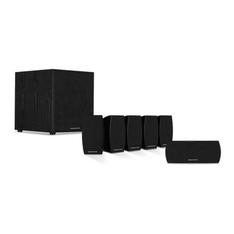
Sonodyne Genie 1 User manual

S
N
O
D
N
Y
E
O
www.sonodyne.com
o w n e r ’ s m a n u a l

Table of Contents
INTRODUCTION
UNPACKING
ABOUT YOUR GENIE I
1. STEREO
SET-UP
A. Genie I as a full range monitor
... Page 1
... Page 2
... Page 5
... Page 3
... Page 4
B. Genie I as satellites in conjunction with a powered subwoofer
2. HOME THEATRE
ACOUSTICS OF THE LISTENING ROOM
PLACEMENT
SPECIFICATIONS
... Page 7
... Page 9
... Page 11
... Page 12
... Page 14
B. Genie I as part of the Genie Power Pack
... Page 6
S
N
O
D
N
Y
E
O
Genie 1

Thank you for choosing Sonodyne. Your Genie speakers are unlike any other speaker system. By choosing this speaker, you are ensured a natural sound
reproduction. The Genie I may be utilized for both music and home theater; as stand alone or in conjunction with our powered subwoofers. Do read on to get
an idea of how these micro monitors may be used.
To help you get listening quickly, we have included here our thoughts on the setup and listening processes. And after you are all set up, do drop us a line
through www.sonodyne.com
Introduction
S
N
O
D
N
Y
E
O
Genie 1 -1-

Unpacking
Your 2 pac or 3 pac carton contains:
!For 2 pac: 2 x Genie Micro Monitors, 2 sets of speaker cables, and 4 bumponÔfeet
!For 3 pac: 3 x Genie Micro Monitors, 3 sets of speaker cables, and 6 bumponÔfeet.
Normally, all speakers require a "break-in" period, i.e., played for sometime so that they can quickly start performing at their best! The same is true for the
Genie I also. If you do not want to do this when you are at home, set your source unit, i.e., CD player, on "repeat entire disc" mode. Then, allow the
speakers to play at moderate volume setting for 6-8 hours
Note: Please retain all packing materials in case you need to transport the Genie Is.
S
N
O
D
N
Y
E
O
Genie 1 -2-

About your Genie I
These micro monitors use hand picked drivers for authentic 2-way design and a low frequency extension of a full octave lower than otherwise possible in a
speaker of this size. The Genie speakers in this carton comprise a tiny 3-inch woofer and a dome tweeter and yet they never sound thin, as do other opposite
numbers from competing brands. The enclosures are aluminium die-cast and so designed as to provide horizontal time alignment between the two drivers.
The small size of the drivers and a minimum centre distance between the two approach the ‘ideal source’ of sound. The trapezoidal shape prevents
st
formation of ‘standing waves’ inside the enclosure which are further damped out with cellulose fibre filling material. A 1 order crossover allows a laid-back
soundstage and resolution extremely difficult for other speakers of this size to attain. Great efforts were put into eliminate ringing - often associated with
metallic structures - by coating the entire inner part of the enclosure with specially formulated rubber paint. And, above all, our ears and years of sound
experience approved them.
S
N
O
D
N
Y
E
O
Genie 1 -3-

Set-up
1. Stereo
OptionsinStereomode:
a. Genie1asfullrangemonitors
b. Genie1aspartoftheGeniePowerPack
c. Genie1assatellitesinconjunctionwithapoweredsubwoofer(RoarrIB/IIC)
2.HomeTheatre
S
N
O
D
N
Y
E
O
Genie 1 -4-

1a. Stereo - Genie I as a full range monitor
Recommended stereo amplifier power:
40 watt long term or 55 watt short term
Connections
Genie I has gold-plated binding post terminals, where red indicates + ve
and black, - ve. Please proceed as follows:
1. Turn off the amplifier.
2. Gently pull of the insulation at the cable ends (which have been pre-
cut at the factory prior to shipping)
3. Twist the strands of the wire together.
4. Turn the gold-plated binding posts counter-clockwise until the twisted
wires can be easily inserted into the holes.
5. Insert the wires, making sure red is +ve and black ,-ve & then turn
The binding posts clockwise to secure the cables in the terminals.
6. Ensure that the connection is a tight fit.
7. Similarly, follow steps 2-6 at the amplifier end to complete the
connections.
~
WARNINGSHOCK HAZARD DO NOT OPEN
RISKOF ELECTRIC SHOCK
DONOT OPEN
CAUTION !
RL
L
R
Genie 1 Genie 1
Note:
A. Verify that the wires from +ve and -ve cables do not touch each other, as short-circuit
could damage the amplifier's output stage
B. Verify that the speaker is in proper phase; the red terminal on the speaker is connected
to the blue terminal on the amplifier and similarly for the black terminals.
S
N
O
D
N
Y
E
O
Genie 1 -5-

Please refer to the Genie Power Pack Manual
1b. Stereo - Genie I as part of the Genie Power Pac
S
N
O
D
N
Y
E
O
Genie 1 -6-

The Genie I has gold-plated binding post terminals, where red indicates
+ve and black, -ve. Please proceed as follows:
1. Turn off the amplifier.
2. Connect the powered subwoofer to the amplifier as described in the
subwoofer owners manual under speaker/ high level connections.
To connect the Genie I to your powered subwoofer:
3. Gently pull of the insulation at the cable ends (which have been pre-
cut at the factory prior to shipping)
4. Twist the strands of the wire together.
1c. Stereo - Genie as satellites in conjunction with a powered subwoofer (Roarr IB/IIC)
Continued …
Recommended stereo amplifier power while operating the Genie Is in
satellite mode:
Not greater than 60 watt long term or 85 watt short term
Connections for Genie in satellite mode:
In this setup, the Genie is connected to the amplifier indirectly, via the
high pass output of a powered subwoofer (Roarr IB/IIC), and thus
operates as a satellite speaker with the powered subwoofer as lower mid
and bass reinforcement. This also results in effective power handling
increase for the Genie since it is not asked to reproduce the bass
frequencies.
S
N
O
D
N
Y
E
O
Genie 1 -7-

Continued …
5. Turn the gold-plated binding posts counter-clockwise until the
twisted wires can be easily inserted into the holes.
6. Insert the wires, making sure red is +ve and black, -ve then turn
the binding posts clockwise to secure the cables in the terminals.
7. Ensure that the connection is a tight fit.
8. To the other end of the wire, repeat steps 2 & 3
9. Insert this end into the speaker level outputs of your powered
Subwoofer.
~
WARNINGSHOCK HAZARD DO NOT OPEN
RISKOF ELECTRIC SHOCK
DONOT OPEN
CAUTION !
To speakers
RL
L
R
Pre out/subout
+
+
-
-
Note:
A. Verify that the wires from + ve & -ve cables do not touch each other, as short-circuit could
damage the amplifier's and / or the powered subwoofer's output stage.
B. Verify that the speaker is in proper phase; the red terminal on the speaker is connected
to the red terminal on the powered subwoofer and similarly for the black terminals
C. While operating in this mode, it is best to use the Roarr powered subwoofers by
Sonodyne and if so, to set the crossover of the Roarr IB/ IIC between 100 and 120 Hz
S
N
O
D
N
Y
E
O
Genie 1 -8-
1c. Stereo - Genie as satellites in conjunction with a powered subwoofer (Roarr IB/IIC)

Continued...
2. Home Theater
Recommended A/V receiver/power amplifier power while operating
the Genie 1s in 'small speaker' mode:
Not greater than 60 watt long term or 85 watt short term
Connections
The Genie I has gold-plated binding post terminals where red
indicates +ve and black, -ve. Please proceed as follows:
1. Turn off the receiver/ amplifier.
2. Gently pull of the insulation at the cable ends (which have been pre-
Cut at the factory prior to shipping)
3. Twist the strands of the wire together.
4. Turn the gold-plated binding posts counter-clockwise until the twisted
wires can be easily inserted into the holes.
5. Insert the wires, making sure red is +ve and black, -ve and then turn
the binding posts clockwise to secure the cables in the terminals.
6. Ensure that the connection is a tight fit.
7. Similarly, follow steps 2-6 at the amplifier end to complete the
connections. Connect FL & FR speakers to the Front/ Main Left &
Right on the amplifier/ receiver, C speakers to the Center channel on
the amplifier/ receiver and LS/ RS speakers to the Surround Left &
Right channels on the amplifier/ receiver
S
N
O
D
N
Y
E
O
Genie 1 -9-

2. Home Theater
Continued...
8. Then, connect the powered subwoofer to the A/V Receiver by
referring to its owner’s manual
9. While setting up your A/V receiver, please indicate that you are using
'small' speakers. Refer to your A/V receiver's owner's Manuals for set-
up details
Note:
A. Verify that the wires from +ve and -ve cables do not touch each other, as short-circuit
could damage the amplifier's output stage.
B. Verify that the speaker is in proper phase; the blue terminal on the speaker is
connected to the red terminal on the amplifier and similarly for the black terminals.
C. You must set the speaker parameter to "SMALL" on the A/V amplifier/ receiver. The
reason for doing this is to optimize bass management since most receivers introduce
a high pass filter of around 80 Hz to the speakers when this mode is selected.
Failing to do so will not guarantee safe operation of your Genies incase they are fed
The full bandwidth signals from your A/V amplifier/ receiver.
S
N
O
D
N
Y
E
O
Genie 1 -10-

Acoustics of the listening room
The acoustical makeup of your listening room is key in determining how good (or bad!) is the sound that reaches your ear. The contents of a room (carpets,
curtains, furniture etc.), its shape, and the material of which the boundaries are made make or break your sound. The idea is to have a listening area where
the absorptions and reflections are calibrated to attain, as far as possible, a neutral environment. While there are no 'quick fix' formulae to convert a 'room' to
an 'ideal listening room', here are a few things that you might try to attain optimal performance.
In your listening room, clap your hands, snap your fingers, and jingle a ring of keys. If the resulting sound is unintelligible (muffled), and resonating, your
room is inclined toward being reflective.
In this event, you might want to:
Hang up curtains
Lay a carpet/ rug
Introduce book cases/ other racks
In the event that the resulting sound is too damped, your room is inclined toward being absorptive. You might want to remove some of the absorptive
material (like those given above)
S
N
O
D
N
Y
E
O
Genie 1 -11-

Placement
Continued …
BumponÔfeet
1. Your micro monitor packaging comes with bumponä feet that you may
attach to the base of the speaker, as shown here so that you may place
it on your table/ bookshelf. However, the Genie I also has threaded
inserts that allow it to be mounted on the wall, ceiling, On the floor, or on
the table top using the following accessories:
*GWB 1: This wall mounting omni-directional bracket lets
you to mount the Genie on the wall and/or the
ceiling while allowing 360 degrees motion
*GTS 1: This is both a tabletop mount as well as the
Adapter for the Genie floor stand
*GFS 1: Attach this to the GTS 1 and the Genie stands
tall on your floor.
2. While placing the Genie I on a flat surface using the bumpon feet,
keep them within 1-2" of the edge of the surface, than toward the
Rear so that the sound is not colored as a result of diffraction.
3. While listening to music in stereo mode, it is best to keep the
Genies at ear level, with at least 6 to 8 feet between them, and `
angled slightly toward the listening position or the sweet spot. This
should ensure the correct soundstaging. However, since room
acoustics play a large part in determining the performance of
speakers, it is best that you experiment with the positioning to
Attain the optimal Listening settings for your room.
S
N
O
D
N
Y
E
O
Genie 1 -12-

Placement
Continued …
4. In Home Theater setup, the Genie Is being used as main speakers should be placed at ear level, with at least 6 - 8 feet between and angled slightly
siti
o o
toward the listening p Center channel speakers should be placed atop the TV set and angled toward the listening position.
n or the sweet spot.
Surround speakers should be at ear height or higher, and angled toward the listening position. The surround speakers may be mounted on the rear or the
side walls. Experiment for best results.
5. Placement of the powered subwoofer: Please refer to the subwoofer Owner's Manual
S
N
O
D
N
Y
E
O
Genie 1 -13-

Specifications
System 2 way sealed enclosure
Cabinet Aluminium die cast
Transducer Complements 1 x 3" coated cone woofer
1 x polycarbonate dome tweeter
Nominal Impedance 8 ohm
Frequency Response 130 Hz ~ 20 kHz (+/- 3 dB)
Useable Response 100 Hz ~ 20 kHz (- 10 dB)
Sensitivity (2.83V - 1m) 87 dB
Crossover Frequency 5.5 kHz
Continuous Power Handling Full range: (Long term) 40 watt
Full range: (Short term) 55 watt
80 Hz low cut: (Long term) 60 watt
80 Hz low cut: (Short term) 85 watt
Input Gold plated binding post (pair)
Finish Metallic paint (silver/ white/ black)
Grille CR Steel
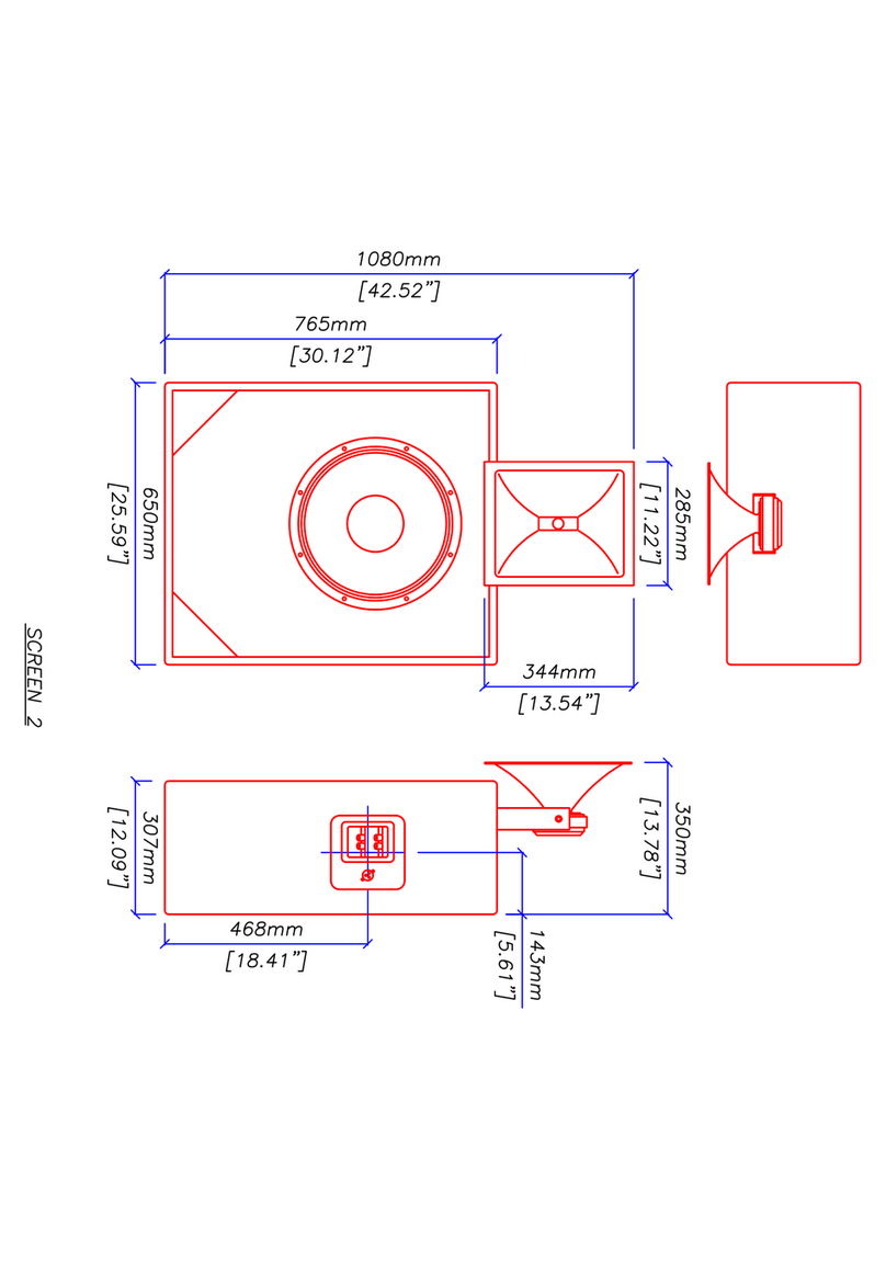
Dimensions (HxWxD) mm 148 x 88 x 110
Internal Volume 0.6 L
Net Weight 1.35 Kg
S
N
O
D
N
Y
E
O
Genie 1 -14-

Manufactured by Sonodyne Electronics Co Ltd
98 NB Block E (1st Floor), New Alipore, Kolkata 700 053
Tel: + 91 33 4570418, 4583406
Fax: + 91 33 4787243
E-mail: [email protected]
Website: www.sonodyne.com
Table of contents
Other Sonodyne Speakers manuals
Sonodyne
Sonodyne PM 4040 User manual

Sonodyne
Sonodyne SRP 350 User manual

Sonodyne
Sonodyne MICRO 3002 User manual
Sonodyne
Sonodyne PM V2 Series User manual
Sonodyne
Sonodyne SM 100Ak User manual

Sonodyne
Sonodyne ExBar perience User manual
Sonodyne
Sonodyne IW 205 LCR User manual

Sonodyne
Sonodyne IWO Series User manual
Sonodyne
Sonodyne Avant 150 User manual
Sonodyne
Sonodyne SPA 110P User manual
