Sonodyne PM 4040 User manual
PM 4040
active speaker system I owners manual
www.sonodyne.com

PM 4040 page 1
INTRODUCTION
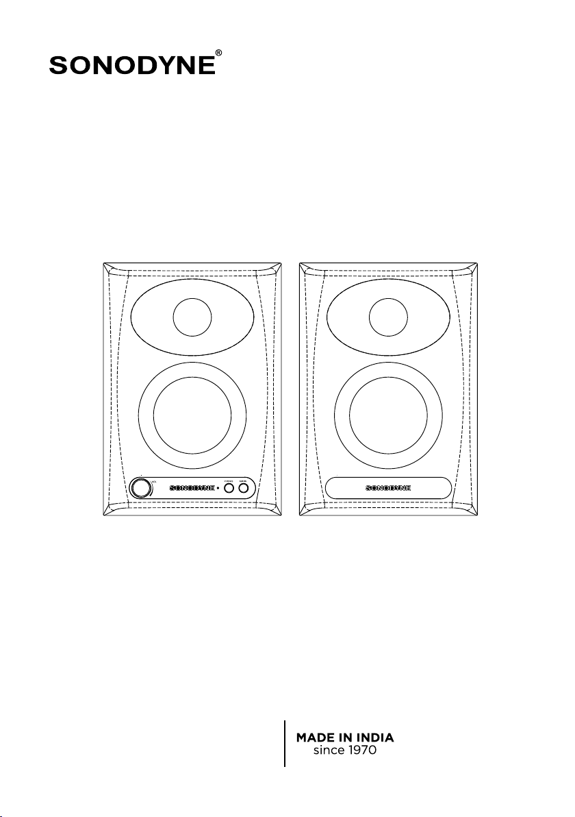
Congratulations on your purchase of the PM 4040 speaker system. The PM 4040 set comprises an active
and passive monitor, wired as left speaker and right speaker. It uses high grade transducers - a 4" glass-
fiber cone woofer, and a 25mm neodymium magnet dome tweeter with an elliptical waveguide built into the
front panel, housed in a bass-reflex type rigid MDF enclosure. These are driven by a highly efficient Class-D
amplifier. A choice of balanced and unbalanced inputs on rear panel, an additional unbalanced input through
Aux on the front panel, front-mounted headphone output and volume control, provide all the essential
features required of such a monitor.
SAFETY
• Please ensure proper earthing.
• Please keep away from moisture.
• Ensure that the speakers are not covered while in use. Restricted airflow at the rear of the unit will
cause it to heat up.
UNPACKING
While removing the units from the carton, please do not hold the speaker’s front. The high frequency
transducer is located near the top of the cabinet, on the front baffle; you may accidentally damage the
transducer.
The best way to safely unpack the monitors is to open the top of the carton, spread the flaps of carton wide
apart and turn the entire carton upside down.Then simply pull off the carton. Next remove the packing
buffers and protective bag
INTRODUCTION •SAFETY •UNPACKING
PM 4040 page 2
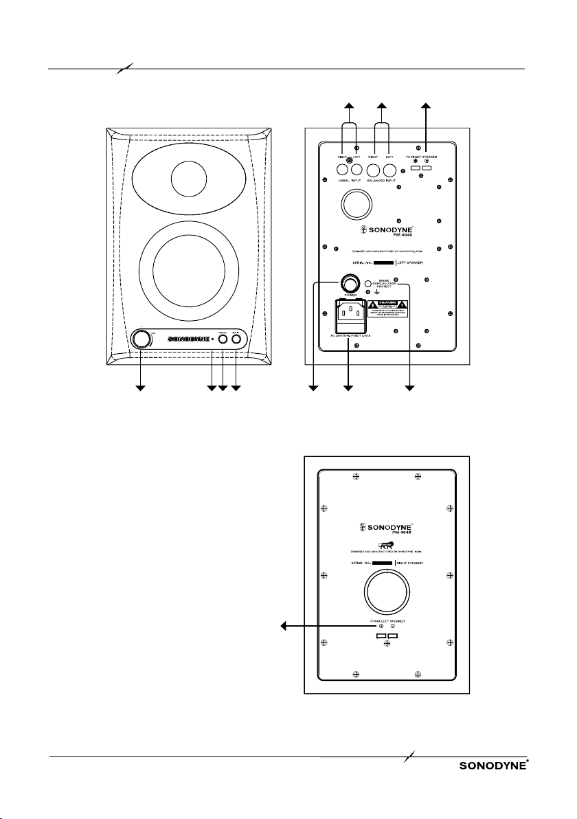
FIG. 1
1 2 3 4
.
1 2 3
4 5 6
3

CONTROLS & FEATURES
PM 4040 page 3
FRONT PANEL (Refer to Fig. 1 on page 2)
1. VOL. CONTROL
This controls the level of both the left and right speakers. Use it to set the listening volume
2. POWER INDICATOR
This lights up when power is ON
3. PHONES
Connect a pair of 1/8th headphones to this socket if you wish to monitor through headphones.
Note that the internal speakers will get disconnected when you plug in the headphone jack.
4. AUX IN
This is a 3.5 mm stereo socket for connecting a line-level unbalanced input.
REAR PANEL (refer to Fig. 1 on page 2)
1. UNBALANCED INPUT
This is an RCA unbalanced type input. Connect your source to this socket if it has an unbalanced
input
2. BALANCED INPUT
This is a fully balanced TRS input socket.
Pin connections are TIP-Positive, RING-Negative, SLEEVE-GND
3. SPEAKER TERMINALS
There are a pair of speaker terminals on both the active speaker (left) and the passive speaker (right).
These are to be connected with the speaker cable supplied. Take care to connect the + terminal of
one speaker to the + of the other speaker, and vice versa.
4. POWER SWITCH
This switch is used to turn power on or off
5. AC SOCKET
This is a fused 3-pin IEC AC receptacle for connecting to a wall outlet with the cable supplied. Ensure
that the wall outlet is properly earthed, that is, the earth must be connected to a earth bus-bar which
connects to other audio equipment and is not shared by noisy equipment like computers, air-
conditioners, lighting appliances etc. The earth connection is also required in the interests of your
own safety, should any fault occur. Please check that the wall outlet is capable of providing the current
requirement of the product, printed on the back panel near the IEC AC socket.
6. OVER-VOLTAGE PROTECT LED
The PM 4040 has a protection feature which automatically shuts off the power when the mains
voltage crosses an upper limit. In such case, this LED will glow. Normal operation will resume when
the over-voltage condition is removed.
SLEEVE
RING
TIP

PM 4040 page 4
INSTALLATION • FIG. 2
ROOM PLACEMENT
The PM 4040 has a wide variety of placement options. Shown in Fig. 2 is a typical stereo setup for near field
monitoring.
The monitors should be angled to directly face the listener. The center of the high frequency transducer
should be on-axis with the ear level of the listener. Keep the PM 4040 at least 2" away from rear wall so as
not to block the port on rear
LISTENING DISTANCE
The common listening position at mixing positions is generally 1 to 1.5m for near field applications. The
stereo listening angle is more a matter of personal preference, but we recommend the angle should be
around 60° as shown in Fig. 2
MOUNTING OPTIONS
For mounting the speaker on a wall 2 inserts are provided on the base as shown in Fig. 3
FIG.2
PM4040
PM 4040
1.5 to 2m
60º

OPERATION
Connect the speaker terminal on the passive or R speaker to the speaker terminal on the active or L speaker
with the cable supplied. Take care to maintain correct polarity
Connect the line level monitor signal from your mixer (or any other source) to the signal input on the PM
4040 using balanced cables (3 pin XLR).
Connect the supplied AC power cord to the IEC socket at rear panel. Keep the power switch at OFF position.
Keep the volume control on PM4040 at minimum Switch on your source.
Switch on PM 4040. The blue power LED will light up.
Adjust the volume to get the desired listening level.
NOTE Your PM 4040s achieve their best bass response in a room that is optimized for bass reproduction.
Factors such as room shape and volume, absence of acoustical treatment can prove to be a bane for optimal
sound reproduction from the PM 4040.
MAINTENANCE
No user serviceable part is present inside the unit. All maintenance and repair work are to be undertaken by
qualified personnel only.
OPERATION •MAINTENANCE •FIG. 3
FIG. 3
BOTTOM VIEW
M6 INSERT(2x)
80.00 mm 80.00 mm
PM 4040 page 5

SPECIFICATIONS
DESCRIPTION 2-way stereo active and passive monitor
TRANSDUCER COMPLEMENTS
LF: 4" glass-fiber cone woofer
HF: 25 mm silk-dome neodymium magnet tweeter
with elliptical waveguide built into front panel
ENCLOSURE TYPE Vented, through rear-firing aerodynamic port
ENCLOSURE MATERIAL MDF
FREQUENCY RESPONSE (±3dB) 70Hz ~ 20kHz
MAX SPL, HALF SPACE 109dB peak per pair
CROSSOVER FREQ 2.5kHz
AMPLIFIER TYPE Class D
OUTPUT POWER RMS 60W
INPUT LEVEL FOR 90dB SPL AT 1M 0dBU
INPUT IMPEDANCE 22kΩ
INPUT
Balanced inputs via TRS socket at rear
2 unbalanced inputs via RCA socket at rear
1/4th phones socket at front
OUTPUT Snap-type speaker terminal for connecting to
passive speaker
CONTROLS & SWITCHES (ACTIVE SP)
REAR
FRONT
Power switch
Volume control
INDICATOR Power ON /OFF, on front panel
POWER REQUIREMENT 230V AC, ± 10%, 50Hz
PROTECTION Over current, Overheat, RFI, Switch on/off
FINISH Black matt
DIMENSIONS (HxWxD)
PRODUCT
SHIPPING
230mm x 160mm x 190mm
285mm x 400mm x 245mm
NET WEIGHT
PASSIVE SPEAKER
ACTIVE SPEAKER
2.6kg
3.2kg
NOTE: Due to continuous improvements, all specifications are subject to change
PM 4040 page 6

HORIZONTAL POLAR PLOTS
PM 4040 page 7
-180
-150
-120
-90
-60
-30
0 Deg
30
60
90
120
150
180
dBR
-50
-45
-45
-40
-40
-35
-35
-30
-30
-25
-25
-20
-20
-15
-15
-10
-10
-5
-5
0
0
CurveF reqB WQ DI
1.25K 119 3.0 4.8
1.77K 114 3.1 5.0
2.50K 105
3.4 5.4
-180
-150
-120
-90
-60
-30
0 Deg
30
60
90
120
150
180
dBR
-50
-45
-45
-40
-40
-35
-35
-30
-30
-25
-25
-20
-20
-15
-15
-10
-10
-5
-5
0
0
CurveF reqB WQ DI
3.54K 105
3.4 5.4
5.00K 117 3.1 4.9
7.07K 100
3.6 5.6
-180
-150
-120
-90
-60
-30
0 Deg
30
60
90
120
150
180
dBR
-50
-45
-45
-40
-40
-35
-35
-30
-30
-25
-25
-20
-20
-15
-15
-10
-10
-5
-5
0
0
CurveF reqB WQ DI
10.00K 90 4.0 6.0
14.14K 55 6.5 8.1
20.00K 25 14.2 11.5

VERTICAL POLAR PLOTS
PM 4040 page 8
-180
-150
-120
-90
-60
-30
0 Deg
30
60
90
120
150
180
dBR
-50
-45
-45
-40
-40
-35
-35
-30
-30
-25
-25
-20
-20
-15
-15
-10
-10
-5
-5
0
0
CurveF reqB WQ DI
1.25K 118 3.1 4.8
1.77K 79 4.5 6.6
2.50K 106 3.4 5.3
-180
-150
-120
-90
-60
-30
0 Deg
30
60
90
120
150
180
dBR
-50
-45
-45
-40
-40
-35
-35
-30
-30
-25
-25
-20
-20
-15
-15
-10
-10
-5
-5
0
0
CurveF reqB WQ DI
3.54K 120 3.0 4.8
5.00K 75 4.8 6.8
7.07K 66 5.4 7.4
-180
-150
-120
-90
-60
-30
0 Deg
30
60
90
120
150
180
dBR
-50
-45
-45
-40
-40
-35
-35
-30
-30
-25
-25
-20
-20
-15
-15
-10
-10
-5
-5
0
0
CurveF reqB WQ DI
10.00K 92 3.9 5.9
14.14K 65 5.5 7.4
20.00K 35 10.3 10.1
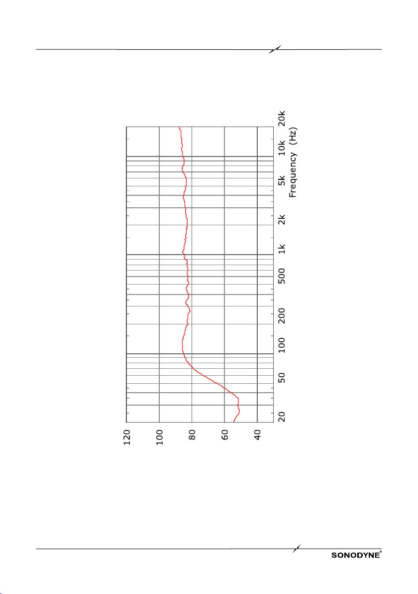
ON-AXIS FREQUENCY RESPONSE
PM 4040 page 9
SPL (dB)

In substitution of any warranty or condition implied, this equipment is warranted against failure arising
through faulty workmanship or material for a period of 24 calendar months from the date of purchase. During
this period, subject to the conditions stated here, the manufacturer will replace or repair any defective part
free of charge (including parts and labour). This warranty is only given with respect to faulty workmanship
and/ or materials and does not cover misuse or consequential damage. Claims under the warranty will be
considered only if the product is returned to an authorised SONODYNE Service Centre directly, or through an
authorized reseller.
• This warranty is applicable only to the original purchaser when purchase is made directly from
SONODYNE or from an authorized SONODYNE reseller. Any claim be accompanied by the original Tax /
GST invoice.
• The warranty DOES NOT COVER:
a. Damage resulting from incorrect installation or use not in accordance with the operating
instruction issued by the manufacturer.
b. Consequential damage.
• This warranty will be rendered invalid if any unauthorized alteration, modification or substitution is
carried out or if the Serial No. is altered and/ or defaced.
• All equipment for servicing must be sent, carriage paid, to an authorized Service Centre, The Company
will accept no responsibility for loss or damage in transit
• If the equipment or any part of it is returned for any cause not covered by the warranty, all costs
involved, including charges for inspection and handling will have to be borne by the customer.
• No reseller has the authority to vary the terms of this warranty.
WARRANTY INFORMATION
PM 4040 page 10

SONODYNE, India •H.O.: 98 NB Block E New Alipore, Kolkata 700053
sonodyneofficial +91 9830855260 sonodyneofficial
Register your product to activate your warranty:
https://sonodyne.com/registerproduct
Upload a picture or video of your Sonodyne product
or write about your Sonodyne experience.
https://sonodyne.com/review
If you have anything less than a 5 star experience,
please contact us at response@sonodyne.com
and we will make it right
Table of contents
Other Sonodyne Speakers manuals

Sonodyne
Sonodyne MICRO 3002 User manual

Sonodyne
Sonodyne SM 100Ak User manual

Sonodyne
Sonodyne Genie 1 User manual

Sonodyne
Sonodyne SLX Series User manual

Sonodyne
Sonodyne Alaap User manual

Sonodyne
Sonodyne Avant 150 User manual

Sonodyne
Sonodyne IWO Series User manual

Sonodyne
Sonodyne IW 205 LCR User manual

Sonodyne
Sonodyne SRP 350 User manual

Sonodyne
Sonodyne PM V2 Series User manual


