Sonodyne IWO Series User manual

IWOIWO
passive speakers I owners manual

• table of contents •
INTRODUCTION page 1
UNPACKING page 1
AMPLIFIER SELECTION page 2
WIRE CONNECTIONS page 2
LINE DRAWINGS page 3 ~ 5
CONNECTION DIAGRAMS page 6 ~ 7
SPEAKER PLACEMENT page 8
ON WALL MOUNTING page 9 ~ 11
IN WALL MOUNTING page 12 ~ 17
ACOUSTICS OF THE LISTENING ROOM page 18
CARE AND MAINTENANCE page 19
SPECIFICATIONS page 20 ~ 21
WARRANTY INFORMATION page 22
IWO 600 Series

• introduction • unpacking •
INTRODUCTION
Congratulations on your purchase of your IWO series loudspeaker. The
IWO Series is a break-through in loudspeaker design for the modern home,
combining style and decor with an amazing sound quality. Elegantly finished in
glossy white or black, it is only 4" deep, and yet produces a full-bodied dynamic
and detailed sound. It can be easily hung on your wall without looking obtrusive.
What’s more, you can even flush-mount on your wall using the ingenious wall-
mounting kit (optional).
As far as performance is concerned, the IWO series ticks all the right boxes -
build quality, design, frequency and dynamic bandwidth, and detailing. Be it for
stereo or multichannel audio, you will find a suitable solution from this range.
So go ahead and play your favourite music and movies and let your eyes and
ears feast.
UNPACKING
Your carton contains:
• 1 x loudspeaker
• Audiophile grade speaker cable, 3m long
Please retain all packing materials in case you need to transport the loudspeaker
We suggest that the loudspeaker be "broken in", i.e., played for some time, so
that it can quickly start performing at its best! If you do not want to do this when
you are at home set your source unit, i.e., CD player on "repeat entire disc"
mode. Then, allow the loudspeaker to play at moderate volume level for 6 - 8
hours.
IWO 600 Series • page 1

amp selection • wire connections •
IWO 600 Series • page 2
AMPLIFIER SELECTION
We recommend using amplifiers whose continuous (rms) power per channel is
greater than or equal to that the speaker handles. Recommended power ratings
of amplifier are given under specifications. Please see page 20 & 21.
In the event that the power is greater, care must be taken to avoid playing music
at excessively loud levels and thus damage the speaker. Also, while using an
amplifier with rms power lower than the rated power handling of the speaker,
please ensure that the amplifier volume is set such that there is no audible
distortion. Lower powered amplifiers, operating at close to maximum volume,
often produce distorted signals at high levels. This can lead to damage of the
high frequency driver, the tweeter.
WIRE CONNECTIONS
Please proceed with the connection in the following fashion:
1. Turn off the amplifier.
2. Gently pull off the insulation on the cable ends (which has been pre-cut at
the factory) and twist the strands on the wire.
3. Insert them into the holes on the gold plated binding posts and turn them to
tighten. Please note the following
A. Verify that the wires from the positive terminal and negative terminal
do not touch each other, as a short-circuit could damage the amplifier.
B. Verify that the loudspeaker is in proper phase: The + (red) terminal on
the loudspeaker is connected to the + (red) terminal on the amplifier.
The - (black) terminal on the loudspeaker is connected to the - (black)
terminal on the amplifier.
The above are illustrated by the following sketch
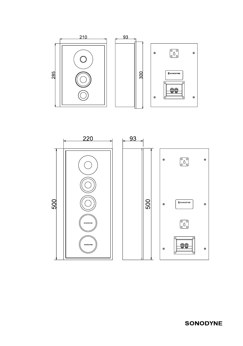
• line drawings •
• IWO 501 •• IWO 611 •
IWO 600 Series • page 3

• line drawings •
• IWO 502 •• IWO 612 •
IWO 600 Series • page 4

• line drawings •
• IWO 621 •• IWO 622 •
IWO 600 Series • page 5

• connection diagrams •
IWO 600 Series • page 6
6a. CONNECTING IWO 501, 502, 611 and 612
The following figure shows the IWO 501, 502, 611 and 612 connected to a stereo
setup.
6b. CONNECTING IWO 501, 502, 611 and 612
connected as the front left and front right speakers in a 5.1 system

• connection diagrams •
IWO 600 Series • page 7
6d. CONNECTING ADDITIONAL IWO 501, 502, 611 & 612
AS SURROUND SPEAKERS
The following figure shows 2 x IWO 501,502,611 and 612 connected as the
surround speakers in a 5.1 system
6c. CONNECTING IWO 621 and 622
The following figure shows the IWO 621 and 622 connected as the center
speaker in a 5.1 (or larger multichannel) system
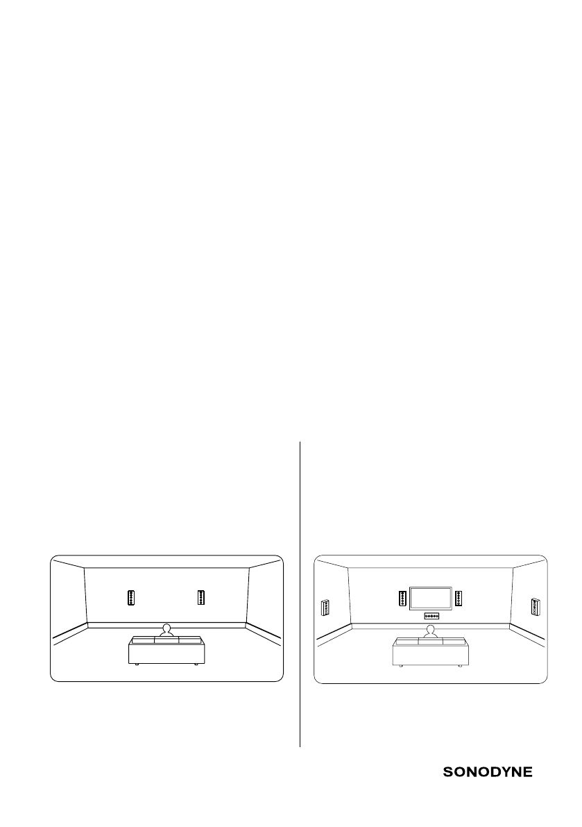
• speaker placements •
The following figure shows a typical
room placement with the 501,502, 611
and 612 connected as the front left and
right speakers in a stereo system
The following figure shows a typical room
placement with the IWO 501,502,611 and
612connected as the front left and right
speakers in a 5.1 system
7a. PLACING STEREO OR FRONT LEFT AND RIGHT SPEAKERS IN
A MULTI-CHANNEL SYSTEM
Finding the right position for the IWO 501, 502, 611 and 612 are also very
important. The following should aid in locating that optimal position:
Ensure that there are no objects between the speaker and the listener in general.
Avoid placing the loudspeakers near corners which will boost the low frequency
level but at the same time create reflections in the midrange and treble area,
which results in a deterioration of the stereo image. As a guideline, for optimum
placement, the distance to the side wall should be at least 50 ~ 80 cm.
The distance between the IWO 501, 502, 611 and 612 should be the same as the
distance from either loudspeaker (left and right) to your preferred listening position
(thus forming an equilateral triangle with the left, right speakers, and you as the
three vertices.) If distances are not a premium, then the optimal position could be
attained by playing a stereo recording, separating the left and right speakers till an
acoustical hole is formed in the middle. Then bring the two speakers together to
attain a uniform sound front.
Another important point to bear in mind while placing the speakers is that the
tweeters of the speaker are at ear level. Detach the grill so you can see the tweeter
IWO 600 Series • page 8
5.1 SURROUND SOUND SYSTEM (3”)

IWO 501 and 502
The IWO 501 and 502 have a key-hole type bracket at the rear, right in the middle, near
the top. You can use this to hang the speaker on the wall, like a picture frame. Please see
figure below.
• on-wall mounting •
IWO 600 Series • page 9
ON WALL MOUNTING

• on-wall mounting •
IWO 600 Series • page 10
IWO 611 and 612
The IWO 611 and 612 have 2 such key-hole brackets, placed vertically on the rear of
the cabinet and at the horizontal center. Fix 2 screws vertically on the wall at a center
distance as follows
• 280mm or 11", for the IWO 611
• 381mm or 15", for the IWO 612
Make sure that the screws lie on the same vertical plane. Hang the speaker on these 2
screws. Please see figure below
ON WALL MOUNTING
IWO 612
IWO 611

• on-wall mounting •
IWO 600 Series • page 11
IWO 621 and 622
These cabinets are supposed to be mounted vertically. Two key-hole type brackets are
provided on the rear, in the same horizontal line on which the cabinet is hung. Fix 2
screws horizontally on the wall at a center distance as follows
• 300mm or 12", for the IWO 611
• 432mm or 17", for the IWO 612
Make sure that the screws lie on the same horizontal line or the speaker will be tilted
when hung. Hang the speaker on these 2 screws. Please see figure below
ON WALL MOUNTING
IWO 621
IWO 622
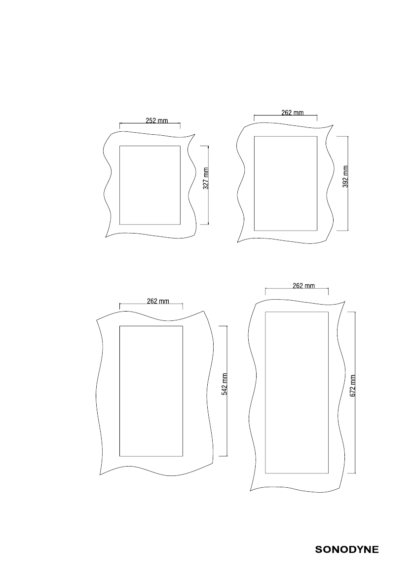
• in-wall mounting •
• cut-out on dry wall •
IWO 600 Series • page 12
Each IWO speaker is provided with mounting inserts on the rear that allow them to be
flush-mounted on a wall with the help of the optional in-wall mounting kit.
First make a cut-out on the dry wall for the IWO speakers as shown in the figure below.
IWO 501
IWO 611
IWO 502
IWO 612

• in-wall mounting •
• cut-out on dry wall •
IWO 600 Series • page 13
Next fit the in-wall mounting kit to the speakers. Proceed as follows
• Detach the magnetic grill and put the cabinet face down on a table. Use a foam or
similar substance so that the cabinet front does not develop any scratch. Position the
kit so that the frame of the kit slides into the cabinet till the metal tongues of the kit
come to rest on the cabinet back.
• Fix the machine screws along with flat washer and spring washer supplied, to hold
the tongues to the cabinet back. Tighten the screws.
• Next fit the plastic accessories known as dog-ears. Slide the dog-ears inside the
plastic tubes on the frame and fix with self-tapping screws supplied. Do not tighten –
ensure that the screws are just mated with the dog-ears.
• Turn the dog-ears so that they are vertical. Hold the metal frame and insert the
cabinet inside the cut-out on the dry-wall.
• Tighten the screws so that the dog-ears hold the metal frame snugly against the dry-
wall.
• Attach the new grill supplied with the kit.
IWO 621
IWO 622

• in-wall mounting •
IWO 600 Series • page 14
FIG. 1

• in-wall mounting •
IWO 600 Series • page 15
FIG. 2

• in-wall mounting •
IWO 600 Series • page 16
FIG. 3
FIG. 4

• in-wall mounting •
IWO 600 Series • page 17
FIG. 5

• acoustics of the listening room •
IWO 600 Series • page 18
The acoustical makeup of your listening room is key in determining how good (bad) is the
sound that reaches your ear. The contents of a room (carpets, curtains, furniture etc.), its
shape, and the material of which the boundaries are made, make or break your sound.
The idea is to have a listening area where the absorptions and reflections are calibrated
to attain, as far as possible, a neutral environment. While there are no ‘quick fix’ formulae
to convert a ‘room’ to an ‘ideal listening room,’ here are some things that you might try to
attain optimal performance.
In your listening room, clap your hands, snap your fingers, and jingle a ring of keys.
If the resulting sound is unintelligible (muffled), and resonating, your room is inclined
toward being reflective. In this event, you might want to: Hang up curtains/ Lay a carpet
or rug/ Introduce book cases/ other racks. In the event that the resulting sound is too
damped your room is inclined toward being absorptive. You might want to remove some
of the absorptive material (like those given above)
CARE & MAINTENANCE
All Sonodyne loudspeakers of the Sonus range are manufactured with modern and
thoroughly tested materials, which normally do not require any maintenance other than
once in a while opening the front grille and vacuuming the cloth. If the loudspeaker's
cabinet becomes greasy you may clean it by moistening a soft cloth with water and a
mild soap to remove the dirt. Then, use a dry cloth to wipe and restore the original finish.
Please DO NOT use scouring powder, petrol, or any sort of alcohol or solvents to clean the
loudspeaker. It will damage the finish permanently.
This manual suits for next models
7
Table of contents
Other Sonodyne Speakers manuals

Sonodyne
Sonodyne Genie 1 User manual

Sonodyne
Sonodyne SPA 110P User manual

Sonodyne
Sonodyne IW 205 LCR User manual

Sonodyne
Sonodyne PM V2 Series User manual

Sonodyne
Sonodyne SM 100Ak User manual

Sonodyne
Sonodyne MICRO 3001 User manual

Sonodyne
Sonodyne MICRO 3002 User manual

Sonodyne
Sonodyne Micro Series User manual

Sonodyne
Sonodyne SLX Series User manual

Sonodyne
Sonodyne Avant 150 User manual


