Sonodyne SPA 110P User manual
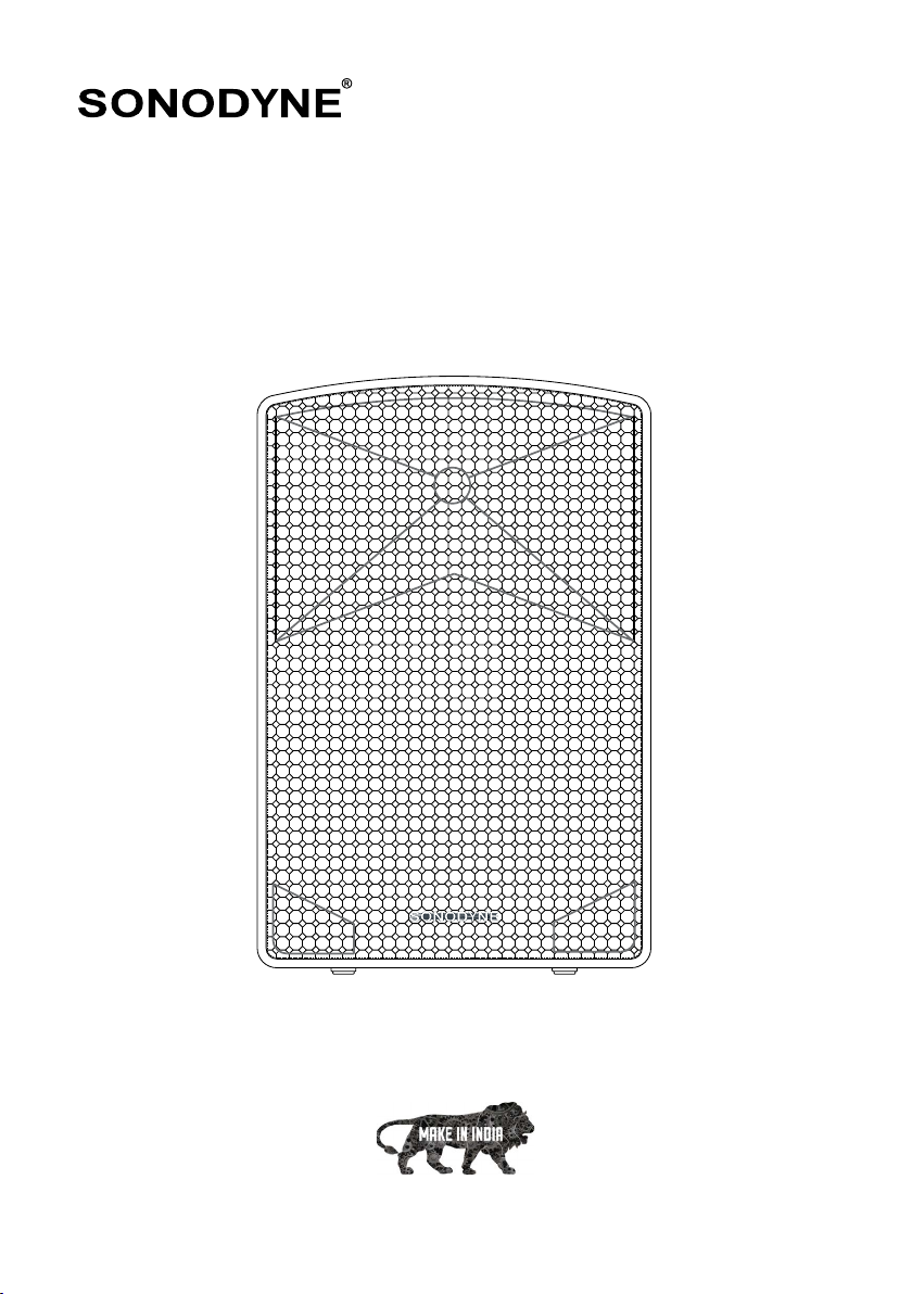
SPA 110P
professional speaker I owners manual
www.sonodyne.com
SPA 110P page 1
IMPORTANT SAFETY INSTRUCTIONS
Congratulations on your purchase of the SPA 110P, 2-way active professional speaker. It can be used for live
sound reinforcement, permanent installations and a variety of other applications.
UNPACKING
To unpack the unit, open the carton by cutting along the edge of the flaps. Push the flaps wide open. Fold
any one flap and tilt the carton on this edge taking care that the flap stays open. Gently turn the carton
upside down so that all the 4 flaps stay open and spread out, and the unit comes to rest on the Styrofoam
buffer. You may need someone to help you with this. Next lift the carton from the unit. Remove the styrofoam
buffer on the bottom of the unit, facing you.
Carefully lift the unit from the styrofoam buffer on which it is resting, strip it of its protective cover and place
it in its intended location.
MOUNTING
The speakers may be mounted on stands. The SPA 110P is equipped with pole- mount sockets, for fixing
to a pole. It can be found at the bottom of the unit, and is capable of accommodating a pole of diameter
35 mm. The pole mount socket has a depth of 90 mm. The speakers may also be used as stage monitor/
wedges.
OPERATION
Connect the balanced output of your mixer or other source equipment to the balanced input (XLR female
connectors) of your speaker. Pin connections are pin1-earth or ground, pin2 – hot or positive, and pin3- cold
or negative. If the output of your source equipment is unbalanced, (which however is not recommended
because of noise pick-up problems), short pin 3 and pin1.
Check that the utility outlet for powering your unit is of matching voltage and frequency printed on the back
panel. Also ensure that it is capable of providing the required power, as printed on the back panel. Connect
the mains cable supplied with the unit, to the utility wall outlet after you have connected all other equipment.
Switch on the console or source equipment first. Switch on power to the monitor last. That way, you will not
hear any nasty turn-on thumps generated by other equipment downstream which may be damaging to your
ears and your speaker. The power indicator at the back of the unit will light up. This indicates that your unit
has powered up and is ready for use.
Keep bass/treble controls in mid-position, initially. Play some recorded source material. Depending on the
placement of your speaker and your personal preference for the type of mix you want, you may want to
adjust the bass/treble controls. While setting the mic/line controls, it is best to keep the master level control
within the 12 o’clock to 3 o’clock range. Doing so will result in clear output. Make sure that the output level
of the source equipment is not set too high or distorted output will occur. Use the mode button to switch
between USB/SD, Bluetooth and FM Radio.
IMPORTANT SAFETY INSTRUCTIONS
1. The unit should be connected only to a wall outlet providing the correct mains voltage and frequency as
printed on the product.
2. Connect the unit to the mains only with the mains cable supplied with the unit.
3. Ensure that the wall outlet is properly earthed, that is, the earth must be connected to a earth bus-bar
which connects to other audio equipment and is not shared by noisy equipment like computers,
air-conditioners, lighting appliances etc. The earth connection must be checked and certified by a
qualified electrical engineer.
4. Do not place the unit on an unstable surface that may topple and cause the unit to fall, thereby causing
injury to the user or other people.
5. Do not place the unit outdoors where it may be exposed to strong sunlight, rain or moisture. Do not
place it near a water body or sprinkler.
6. Do not cover the unit. This may cause it to heat up.
7. Do not place the unit near heat radiating items like stoves, radiator etc.
8. Do not allow liquid or any chemical to spill on or into the product.
9. Do not open the unit or attempt to service it yourself. There is no user-serviceable part inside. Refer
servicing to qualified service personnel only.
10. Replace only with the same type and rating of fuse as printed on the product.
11. Do not overload wall outlets that provide power to this unit.
12. Install the unit by following instructions provided by the manufacturer.
SPA 110P page 2
UNPACKING •MOUNTING •OPERATION
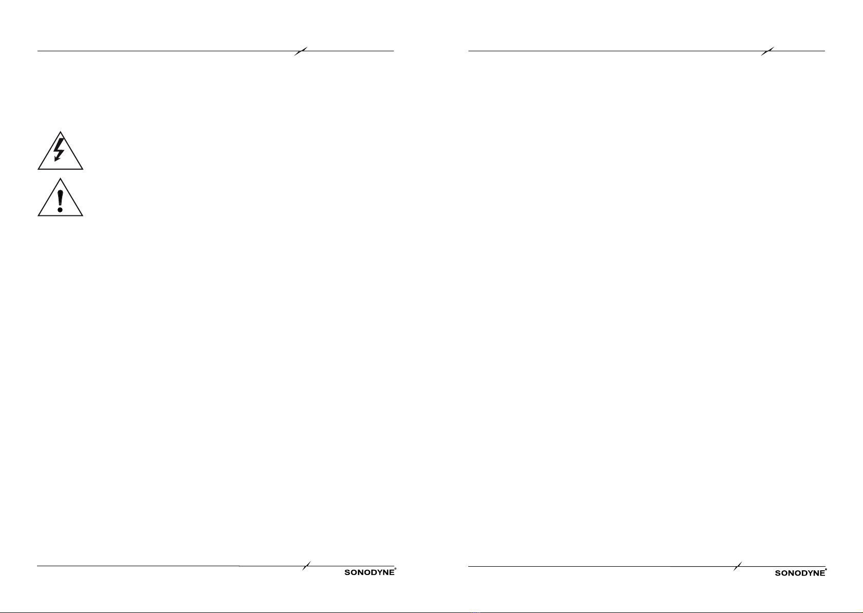
The lightning flash with an arrowhead symbol is intended to warn the user that there is
uninsulated (dangerous) voltage inside the unit.
The exclamation mark within an equilateral triangle symbol is intended to alert the user
of presence of important operating instructions in the owner’s manual accompanying the
product.

CONTROLS & SWITCHES
SPA 110P page 3 SPA 110P page 4
1. USB INPUT
This is a USB input for playing audio tracks recorded on external USB devices. Plugging in a USB
device automatically switches the input mode to USB/SD input. Both Mp3 and WAV file formats are
supported.
2. SD CARD INPUT
This is a SD card input for connecting external SD cards. Plugging in a SD card automatically switches
the input mode to USB/SD input.
3. MP3 PLAYER - DISPLAY
This is a dot-matrix type LED display for the MP3 player. It displays the input selected, the volume level
and the functions of the MP3 player.
4. MP3 PLAYER - CONTROLS (From left to right)
MODE: This is a mode selection button that allows you to switch the input between USB/SD, Bluetooth
and FM radio inputs.
PLAY/PAUSE: This button allows you to play/pause a track. It doubles as a “scan” button while using
the FM radio mode, which scans for available radio stations.
STOP: This button allows you to stop playback while in USB/SD or Bluetooth mode.
SELECT: This button allows you to play tracks in order or on random while in USB/SD mode.
SKIP PREVIOUS: This button allows you to play the previous track/radio station.
SKIP NEXT: This button allows you to play the next track/radio station.
5. MIC IN
This is a balanced XLR microphone input. Pin connections are 1 ground, 2 hot or positive, and 3 cold
or negative.
6. LINE IN
This is a balanced XLR microphone input. Pin connections are 1 ground, 2 hot or positive, and 3 cold
or negative.
7. MIX OUT
This is a balanced, combined output of the line and mic along with USB/SD and Bluetooth. This output
can be connected to the LINE IN on another SPA Powered speaker to expand the system. Pin
connections are 1 ground, 2 hot or positive, and 3 cold or negative.
8. MASTER LEVEL
This control allows you to change the master level. At the extreme anti-clockwise position, the output
is totally muted.
CONTROLS & SWITCHES
1
5
13
14
15
2
3
7
8
9
10
6
4
11
12
16
SPECIFICATIONS
SPA 110P page 5 SPA 110P page 6
DESCRIPTION 2 way active speaker with 10” LF and
horn loaded compression driver
ENCLOSURE Injection moulded professional grade plastic
TRANSDUCER COMPLEMENTS: HF 1" compression driver with 1.1" VC
TRANSDUCER COMPLEMENTS: LF 10" woofer with 2" VC
AMPLIFIER POWER 150W (LF 100W, HF 50W)
AMPLIFIER POWER PROGRAM 300W
MAX SPL 118dB
FREQUENCY RESPONSE (-3dB) 60Hz ~ 18kHz
FREQUENCY RANGE (-10dB) 55Hz ~ 20kHz
DIRECTIVITY (HF H X V) 90° x 50° (HF H x V)
CROSSOVER FREQUENCY 2kHz
INPUTS
Balanced mic: 1
Balanced line: 1
Balanced Mix Out: 1
CONTROLS Level controls: Line, Mic, Master; Bass, Treble
BT VERSION Version 4.2
DIMENSIONS (HXWXD) MM 510 x 330 x 220
USB SD CARD Support WMA, WAV, MP3 files;
Controls: Play / Pause, Stop, Repeat, Next , Previous
NET WEIGHT 12kg
MOUNTING OPTIONS Pole mount, floor monitor
9. BASS
This is a bass control for mic and line input. The bass control allows you to boost or cut the low
frequencies. The control allows a maximum variation of +6dB and -6dB at the two extremes. If you do
not wish to use this control, keep it at its center position.
10. TREBLE
This is a treble control for mic and line input. The treble control allows you to boost or cut the high
frequencies. The control allows a maximum variation of +6dB and -6dB at the two extremes. If you do
not wish to use this control, keep it at its center position.
11. LINE LEVEL
This control allows you to change the level of the line input. At the extreme anti-clockwise position, the
LINE input is totally muted.
12. MIC LEVEL
This control allows you to change the level of the mic input. At the extreme anti-clockwise position, the
mic input is totally muted.
13. POWER SWITCH
This is a rocker type power switch which turns on power to the system. The ON position is indicated
with a mark on the switch.
14. POWER INDICATOR LED
This is a power indicator. It turns on when power is switched on.
15. OVER VOLTAGE PROTECT LED
There is a built-in protection feature which automatically shuts off the system when the mains
voltage crosses an upper limit. In such case, this LED will glow. After the voltage is normal set will
automatically resume operation.
16. IEC AC SOCKET
This is a fused 3-pin IEC AC receptacle for connecting to a wall outlet with the cable supplied. Ensure
that the wall outlet is properly earthed, that is, the earth must be connected to a earth bus-bar which
connects to other audio equipment and is not shared by noisy equipment like computers, air-
conditioners, lighting appliances etc. The earth connection is also required in the interests of your
own safety, should any fault occur. Please check that the wall outlet is capable of providing the current
requirement of the product, printed on the back panel near the IEC AC socket. NOTE: Due to continuous improvements, all specifications are subject to change
CONTROLS & SWITCHES

SONODYNE, India •H.O.: 98 NB Block E New Alipore, Kolkata 700053
sonodyneofficial SonodyneMusic sonodyneofficial
A product of the Mukherjee Innovation Centre
Table of contents
Other Sonodyne Speakers manuals

Sonodyne
Sonodyne MICRO 3001 User manual

Sonodyne
Sonodyne IWO Series User manual

Sonodyne
Sonodyne IW 205 LCR User manual

Sonodyne
Sonodyne Avant 150 User manual

Sonodyne
Sonodyne SM 100Ak User manual

Sonodyne
Sonodyne MICRO 3002 User manual

Sonodyne
Sonodyne SRP 350 User manual

Sonodyne
Sonodyne PM V2 Series User manual

Sonodyne
Sonodyne ExBar perience User manual

Sonodyne
Sonodyne Alaap User manual


