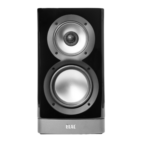
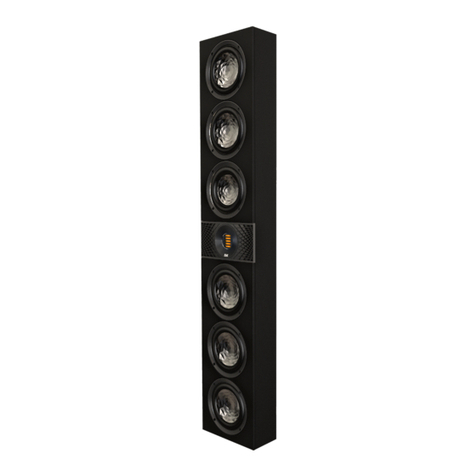
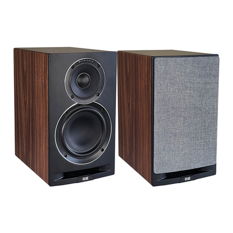
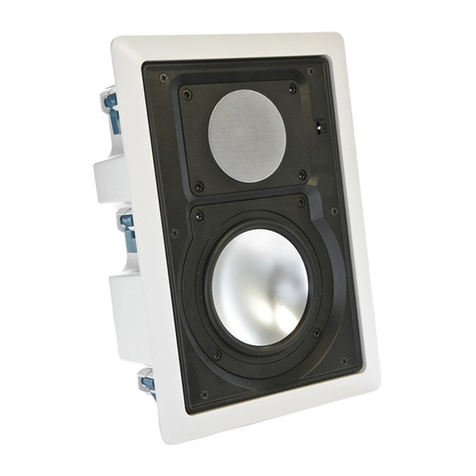
ELAC Uni-Fi UF5IFS U5 User manual

([A[
Uni-Fi
by
Andrew
Jones.
UB5
I
BS
U5
BOOKSHELF SPEAKERS
UF51FS
U5
FLOORSTANDING SPEAKERS
OPERATING INSTRUCTIONS
UC5
I CC
U5
CENTER CHANNEL SPEAKER
Ill[
The
life
of
sound.

Safety Instructions
1.
General information
• Please read and follow these safety instructions.
• Keep them safe
for
future reference.
• ObseNe all warnings on the speaker and
in
the manual. Please check the speaker for damage
before use. The speaker must be
in
perfect working condition. Damaged parts may lead to
personal injury.
2. Use
only
as
directed
• Connect the speaker(s) according
to
the instructions
in
the manual.
• Many
ELAC
speakers are equipped with spikes and/or anti-slip feet. They are explicitly provided for
levelling the speaker. For levelling on
an
uneven floor, unscrew the spikes
or
anti-slip feet
by
2-3
turns
of
thread. The speaker should always be in perfect vertical alignment: the stability
of
the
speaker must not be compromised by using spikes or anti-slip feet
as
the
speaker may tip-over.
3.
Location
• Install the speakers on a level surface only
• When choosing the location
of
these speakers
do
not place them
in
locations that are:
• In direct sunlight
• Very humid
• Prone to vibrations
• Exceptionally hot or cold
• Near
CRT
Televisions (the speakers are not magnetically shielded and may cause color
issues with a
CRT
based TV)
• Close
to
magnetic cards (Since the speakers are
not
magnetically shielded placing
magnetic cards such
as
credit cards
or
commuter cards may cause them
to
fail).
WARNING! Please ensure
the
product
is
perfectly
stab
le
to
avoid
injury
from
tip-over.
Please note, that stability can be increased
by
using spikes on carpeted surfaces. However, the
mounting
of
spikes must be carried
out
carefully due
to
their very sharp ends which may cause injuries.
The stability on slippery floors can be increased
by
using Velcro fastening tape
or
double-sided
adhesive tape. Do not install the speaker near any heat sources such
as
radiators, heating valves,
stoves,
or
other apparatus
(i
ncluding amplifier
s)
that produce heat,
or
in
areas where there is a risk
of
explosion.
• Do
not
block any ventilation openings. Install
in
accordance with the manufacturer's instructions.
• Do
not
install
the
speaker in a closed rack or in a closed cupboard.
• Do
not
put burning candles on or nearthe speaker.
• Do
not
in
stall the speaker near
tr
ansformers because electromagnetic stray fields can
ca
use hum
noise on woofers.
• In combination with certain materials I lacquers I material surfaces, anti-slip feet or spike washers
may cause colored imprints on the surfaces.
ELAC Uni-Fi Speakers I www.elac.com I Page 2

4. Overload
Extreme overload
of
the
device due
to
very high volume may cause damage
to
individual components.
Because
of
the possible danger, you should never leave loudspeakers under extreme overload
conditions unattended.
5. Service
DANGER!
Do
not
open
the
cabinet
because
the
components
and
conductors
may carry current!
Servicing to be carried
out
by qualified service personnel only.
Servicing
is
required when the loudspeaker has been damaged in any way, such
as
damage
to
the
power supply cord
or
the plug,
or
when liquid has been spilled
or
objects have fallen onto the
loudspeaker, the speaker has been exposed
to
rain
or
moisture, does not operate normally,
or
has
been dropped. To reduce the risk
of
electric shock,
do
not open the loudspeaker. Servicing should be
carried out
by
qualified service personnel only.
6.
Cleaning
NOTE:
Clean
only
with
soft, smooth
cloth
or
with
dust brush.
Do
not
use scouring agents,
alcohol, benzene, furniture polish
or
other agents for cleaning! Modern furniture is often coated with
multiple varnishes and plastics which can be treated with chemical agents. Some
of
these agents
contain substances which degrade
or
soften the rubber feet. Therefore
we
advise that you place
an
anti-slip mat underneath the loudspeaker(s).
7. Volume
CAUTION!
Continuous
high
volume
may cause severe
damage
to
your
hearing. Please listen
responsibly.
8. Disposal
The packaging is made from recyclable materials. Dispose
of
this
in
an environmentally friendly
manner.
At
end
of
life
do
not dispose
of
the speaker(s) with standard household waste. The speaker
must be recycled in accordance with local legislation. Ask your local government for further
information on recycling
as
the
dev
ice contains valuable raw materials. Disable the speaker(s) before
disposal.
ELAC Uni-Fi Speakers Iwww.elac.
com
IPage 3

Philosophy
Thank you for purchasing this
ELAC
product.
Since
the time we started (1926),
ELAC
has
always striven to achieve the very best.
Your
new
ELAC
speakers are built to the highest standards using high-quality components that
are
carefully constructed
to deliver the best-
in-class
sound quality. They
are
developed
by
a
pass
ionate group ofindividuals whose
soul
purpose
is
to bring a new dimension ofsound quality into your
home.
Enjoy!
Before Use
Avoid
damage
to
the speakers and
other
components:
• Carefully
unbox
the speakers carefully
to
avoid physically damaging
your
speakers.
• Use appropriate gauge wires (minimum
of
14
gauge wire
for
runs
up
to
25
feet).
• Make sure wire polarity is connected correctly. Most speakercables are coded for ease
of
use. Make sure
positive (red) connection
on
the
amplifi
er
terminal is connected
to
the
positive (red) on
your
speakers.
Follow
the
same instructions
for
the
negative side. Strip
off
approximately
1/2"ofthe
insulation from the
ends
of
the
speaker cable, twist
the
bare strands and insert into
the
binding post.
• Ensure
your
equipment is turned
off
before connecting speakers.
• Check
to
ensure positive and negative wires are nottouching each
other
once they're connected
to
the
speakerterminals.
EL
AC Uni-
Fi
Speakers I
www
.elac.
co
m I Page 4
~
-+
Amplifier

Installing and
Removing
the
Magnetically
Attached
Grills
The mesh grills
of
your Uni-Fi speakers are designed
to
be removable
if
desired. To remove it, hold
the
top
or
bottom edges
of
the grill and pull gently. To replace
the
grill, place the grill
in
the normal position on
the
cabinet and
the
magnets will hold the grill in place.
IMPORTANT!
ELAC UF5 I
FS
U5 Floorstanding Speakers Safety Clip
The
ELAC
UF5 and
FS
U5
Floorstanding speakers include a safety clip pre-installed on
the
back
of
the
cabinet
for
securing
to
a wall
to
prevent tip-over. Use support hooks (not included) screwed into a wall and pass
appropriate size cord (not included) around
the
hook
and through
the
safety clip. Test
to
ensure mounted
hooks and cord will preventtipping
of
the
speaker.
Support
Hooks
& Cords (notincluded)
UFS
Floorstanding Speaker
SafetyClip (pre-installed) Wall
CAUTION:
The safety clip is
not
a mounting fixture and
the
speaker should not be hung on the wall using the clip. ELAC
does not claim responsibility
for
damage resulting from improper assembly, installation, insufficient strength
of
the
installation materials, misuse, or natural disasters.
ELAC Uni-Fi Speake
rs
Iwww.elac.com I Page 5

Outrigger
Feet
&Spike Installation (UF5/FS
us
Only)
Using the included outrigger feet provide a
wider
support base for
the
speaker cabinet. The included spikes improve stability
on uneven surfaces and thickly carpeted floors. Please use caution when dealing with the spikes
as
they
are sharp.
IMPORTANT:
When
using
these
spikes
on
hard surfaces such as
wood
or
tile
floors
be
sure
to
use
the
provided
floor
discs
to
protect your floor from damage.
1
2
3
4
5
IMPORTANT: In
order
to
prevent
scratching
or
damage
to
the
cabinet,
turn
the
speaker
upside down
onto
a soft surface while you attach
the
outrigger
feet and spikes.
We
highly
recommend a second person help with this process.
Attach
the
outri
gger
plates
with
the
provided machine
screws.
································~······~···············~
Screw in the spikes
as
shown in the
picture
to
the right. The speaker can
now
be
turn back over. Please
be
careful when handling
the
speaker
with
the
spikes installed.
If
you have
hard
wood
ortile floors please use
the provided floor discs.
Using
the
supplied allen wrench ad-
just
the
height
of
the spikes until
the
speaker sits level and all four spikes
are touching
the
floor.
Once
the
speaker is level, use
the
supplied covers
to
lock
the
spikes
into place.
. . . . . .
. . . .
. .
1?
~
..
--
--<h
.---
·
~
i
_j----'--------c=;-------=----cs---'----!
1
6-:l
I •
ELAC Uni-Fi Speakers I
www
.elac.c
om
I Page 6

Speaker
Placement
Achieve maximum performance and optimal sound quality from your ELAC Uni-Fi speakers with proper
speaker placement and set-up. While
not
all rooms are
the
same, use
the
following guidelines
to
configure
the
speakers for
your
particular room. There are no "exact" rules or boundaries in setting up your speakers
but
the following suggestions will help optimize your desired results. Remember the best sound set-up is what
sounds best
for
you so
don't
be
afraid
to
experiment and make adjustments
to
the placement and directivity
of
the speakers.
WALLS
~
'r
..
-
..
-
..
-
..
-
..
-
..
-
..
-
..
-
..
-
..
-
..
-
..
-
..
-
..
-
..
-
..
-
..
~
l
1'-2'FEET
I
I :
:
~
~
I
I L5J
Ls.J_..
_.:
I :
1-2
FEET
!
FIG.1
Place the speakers approximately one
to
two
feet
away (fig.
1)
from boundaries such
as
wall(s) and especially
corners. Close proximity
to
a side
or
rear wall will enhance bass performance (output), but being
too
close
(particularly
to
a corner) may result in bass that is unnatural. Ifa corner location is unavoidable, try
to
position
the
loudspeaker so that
the
distance
to
the
rear wall
is
not
equal to
the
distance to the side wall.
ELAC Uni-Fi Speakers I
www
.elac.c
om
I Page 7

Stereo Setup
• For
the
best results and the most realistic stereo image and lifelike sound, place
the
speakers so that
an
equilateral triangle (fig.
2)
is created between the speakers and your favori
te
listening position. This set
up creates the optimum imaging performance.
• Ifyou find that your front left and right speakers are
too
far apart, angle (toe in) them towards the listening
position
to
gain a more focused central image .
LEFT
SPEAKER
RIGHT
SPEAKER
TV
&
CENTER
SPEAKER
w
I : : I
__
:
,,
.
:
.
"·
.::
'· .· :
. ··
····
·
····························
·
···
···
··
·
··
·
········
·
···································:
'
LISTENING
POSITION
FIG.2
2- CHANNEL STEREO SETUP
ELAC Uni-Fi Speakers I
www
.elac.com I
Pag
e 8

Surround Sound Setup
Whether you use
the
Uni-Fi bookshelf
or
the Uni-Fi floorstanding speakers
for
a 5.1-channel surround set-up,
avoid placing the surround speakers forward
of
your listening position. The surround speakers should be
spread apart wider than
the
front speakers.
In
addition, elevate the speakers
to
the
same height or slightly
higher
as
the front speakers for the most enveloping sound field. Like the front speakers. you may need to
experiment with
the
positioning
by
pointing the rear surround speakers towards the listening area.
r·
····
·
···
·····
-
; '
: (
__
~.
·_-_
-
::_
)
·
-----
~
-
---
I : _ : I
w.
::
.::
•
.
/
',
,;...:.,
,' \
.
.,'
',
\
..................................................
..
.......................................................
}'
'
..
....
..
...
-
..
..
-
.........
..
....
..
...
-
..
..
....
.
..
..
-
..
.........
-
..
..
......
...
-
•.
·
·......
-
..
..
..
.
..
..
~----~~-
\
+·--~-~
-
-~----~
~
··..
-
.................
""""'"'""'"'(""""'
.......................
......
:
:·
(!,
........
.......................
""""'
"
)"''"'"''"'"
'
''"""""
.....
..
......
.
.....
........
-
·-
-·-
·-
·--
--·-
---.
..
U
PT
0
......
_c.........
--·----·-
1
..
__
20
DE
GREES
G.
....
...
::·~-~--~··:··~--
~
··
~
-
LISTENING
POSITION
-~-
~
-
-
---
~=
-~
·=··:·-
I:]
LEFT
REAR
SURROUND
5.1-CHANNEL
SURROUND
SET-UP
ELAC Uni-Fi Speakers I
www
.ela
c.
c
om
IPa
ge
9
RIGHT
REAR
SURROUND

Center Speaker Setup
The ELAC UC5/CC
US
center channel
is
designed
to
produce dialog sounds and should
be
positioned above
or
below
(fig.
3)
your television. Align it with
the
center
of
the
television. As much
as
possible,
try
to keep the
UC5/CC
US
close to
the
same level (height) as your front speakers for a more even sound stage. Keeping the
same height
for
the center channel can
be
very challenging so it might
be
necessary
to
tilt the center speaker
up
(if
too
low)
or
down (if
too
high),
to
aim ittowards
the
listening area.
FIG. 3
D
D
PLACE
ABOVE
OR
BELOW
1
C:J
---
--
-
-
I ------
I
I
I
I
I
I
L -- - - -
-----
--
- -
1
~1
TELEVISION
1~1
-
--
-----
--
-
-
---
-
~
r
- - - - - - - --
Opt
imal results
for
the
center are obtained
by
setting
the
receiver/processor center channel size
to
small.
If
you have a choice, set
the
crossover frequency between
50
to
100Hz.
ELAC Uni-Fi Sp
eake
rs I
www
.elac.
com
I P
age
10

SPECIFICATIONS
UB51-K UF51-K UC51-K
Enclosure Type 3-Way Bass Reflex 3-Way Bass Reflex 3 - Way Bass Reflex
Frequency Response
46Hz-25000Hz
42Hz-25000Hz
48Hz -
25000hz
Nominal Impedance
40hms
40hms
40hms
Sensitivity
85db@
2.83v/1m
85db
@2.83v/1m
85db
@2.83v/1m
Crossover Frequency 270 I
2700Hz
270 I 2700Hz 270I 2700Hz
Max Power Input 140 Watts 140 Watts 140 Watts
Tweeter
1"
Cloth Dome
1"
Cloth Dome
1"
Cloth Dome
Midrange
4"
Aluminum 4" Aluminum
4"
Aluminum
Woofer 5.25 Inch Aluminum 3 x 5.
25
Aluminum 2 x 5.25 Inch Aluminum
Cabinet CARB2 Rated MDF CARB2 Rated MDF CARB2 Rated MDF
Cabinet Finish Black Brushed Vinyl Black Brushed Vinyl Black Brushed Vinyl
Port Dual Flared 3 x Dual Flared 2 x Dual Flared
Binding Posts 5-Way Metal 5-Way Metal 5-Way Metal
Dimensions (WxHxD) 7.87" X 12.75" X 10.75" 7.87" X 38" X
10
.75"
18
.75" X 7.87" X
10
.75"
BS U5-SW/SB
FS
U5-SW/SB CC U5-SW/SB
Enclosure Type 3-Way Bass Reflex 3-Way Bass Reflex 3 - Way Bass Reflex
Frequency Response
46Hz-25000Hz
42Hz-25000Hz
48Hz -
25000hz
Nominal Impedance
40hms 40hms
40hms
Sensitivity
85db
@2.83v/1m
85db
@2.83v/1m
85db
@2.83v/1m
Crossover Frequency 270 I 2700Hz 270 I 2700Hz
270
I 2700Hz
Max Power Input
140
Watts 140 Watts 140 Watts
Tweeter
1"
Cloth Dome
1"
Cloth Dome
1"
Cloth Dome
Midrange
4"
Aluminum 4" Aluminum 4" Aluminum
Woofer 5.25 Inch Aluminum 3 x 5.25 Aluminum 2 x 5.25 Inch Aluminum
Cabinet CARB2 Rated MDF CARB2 Rated MDF CARB2 Rated MDF
Cabinet Finish Pa
int
ed Satin Whi
te
/Black
Pa
inted Satin White/Black Painted
Sa
tin White/Black
Port Dual Flared 3 x Dual
Fla
r
ed
2 x Dual Flared
Binding Posts 5-Way Metal 5-Way Metal 5-Way Metal
Dimensions (WxHxD) 7" X
13
.35" X
11.54"
7" X 38.58" X
11.
54"
19
.
61"
X 7" X
11.54"
ELAC Uni-Fi Speakers I
www
.elac.
co
m I Page
11

ELAC
Americas
LLC.
North
America
Limited
Liability
Warranty
Passive
Speakers
(No Built-in
Amplifier)
ELAC Americas
LLC.
warrants
to
the original purchaser that this product be free from defects
and or workmanship for a period
of
3 (Three) years from
the
original date
of
purchase. During
this time period, repair
or
replacement
of
parts will
be
free
of
charge to the original
owner
(See
below
limitations). Shipping
to
and return from the repair center will be the responsibility
of
the
original purchaser.
Limitations
• Warranty begins on the date
of
original purchase from an authorized ELAC Americas
LLC
dealer.
• Product
is
warranted only
if
used in home applications within the max
power
rating
specified in this manual. Commercial use
of
this product is notwarranted.
• Product that has been modified
or
altered in anyway will
not
be warranted.
• Product that has been abused
or
subjected
to
faulty equipment will
not
be
warranted.
• Products with defaced
or
removed serial numbers will
not
be
warranted.
If
service
is
required
In
the
event
that service is required, please contact ELAC Ameri
ca
at
714-252-8843 or
at
info@elac.us
to
arrange for service
or
replacemen
t.
You will
be
responsible
to
provide
proof
of
purchase (Copy or original sales receipt). Shipping
to
and from our repair center will
be
the
responsibility
of
the original purchaser.
Warranty
Outsi
de
of
North
America
This warranty applies
to
products purchased in the United States and Canada. For warranty
claims outside
of
North America please contact the local dealer/distributor in
the
country
of
purchase.
ELAC Uni-Fi Speakers I
www
.elac.com I Page 12

Ill[
The
life
of
sound.
ELAC AMERICAS LLC.
11145
KNOTT AVE. SUITES E & F
CYPRESS,CA.
90630
ELAC ELECTROACUSTIC GMBH
FRAUNHOFERSTRA~E16
D-
24118
KI
EL, GERMANY
This manual suits for next models
8
Table of contents
Other ELAC Speakers manuals
ELAC
ELAC A4 User manual
ELAC
ELAC DCB41 User manual

ELAC
ELAC DCB41 User manual
ELAC
ELAC Debut Reference DBR62 User manual
ELAC
ELAC Vertex III Series User manual
ELAC
ELAC Carina Series User manual
ELAC
ELAC Uni-Fi 2.0 User manual
ELAC
ELAC Contractor Series IC-C61-W User manual

ELAC
ELAC Carina BS243.4 User manual

ELAC
ELAC Debut Reference DBR62 User manual
