Sonotec Airborne Sound Sensor BS10 User manual
Operating Manual
BS10
Broadband airborne sound sensor for the SONAPHONE handheld unit
Translation of the German Original
Revision: 2.1 | 2023-04-27

Operating Manual | Content
BS10
2 / 23
Revision: 2.1 | 2023-04-27
Content
1Introduction .......................................................................................................................3
1.1 Notes on this documentation.........................................................................................3
1.2 Representations in this documentation........................................................................3
1.3 Identification of warning instructions ...........................................................................4
2Safety instructions............................................................................................................5
2.1 Introduction......................................................................................................................5
2.2 Basic hazards...................................................................................................................5
2.3 Personnel and qualifications..........................................................................................6
2.4 Safety-conscious working practices ............................................................................6
2.5 Use of the product ..........................................................................................................7
2.6 Modifications and alterations.........................................................................................8
3Description of the sensor..................................................................................................9
3.1 Intended use ....................................................................................................................9
3.2 Prohibited use..................................................................................................................9
3.3 Working principle...........................................................................................................10
3.4 Sensor construction......................................................................................................10
3.5 Sensor identification ..................................................................................................... 12
3.6 Accessories....................................................................................................................13
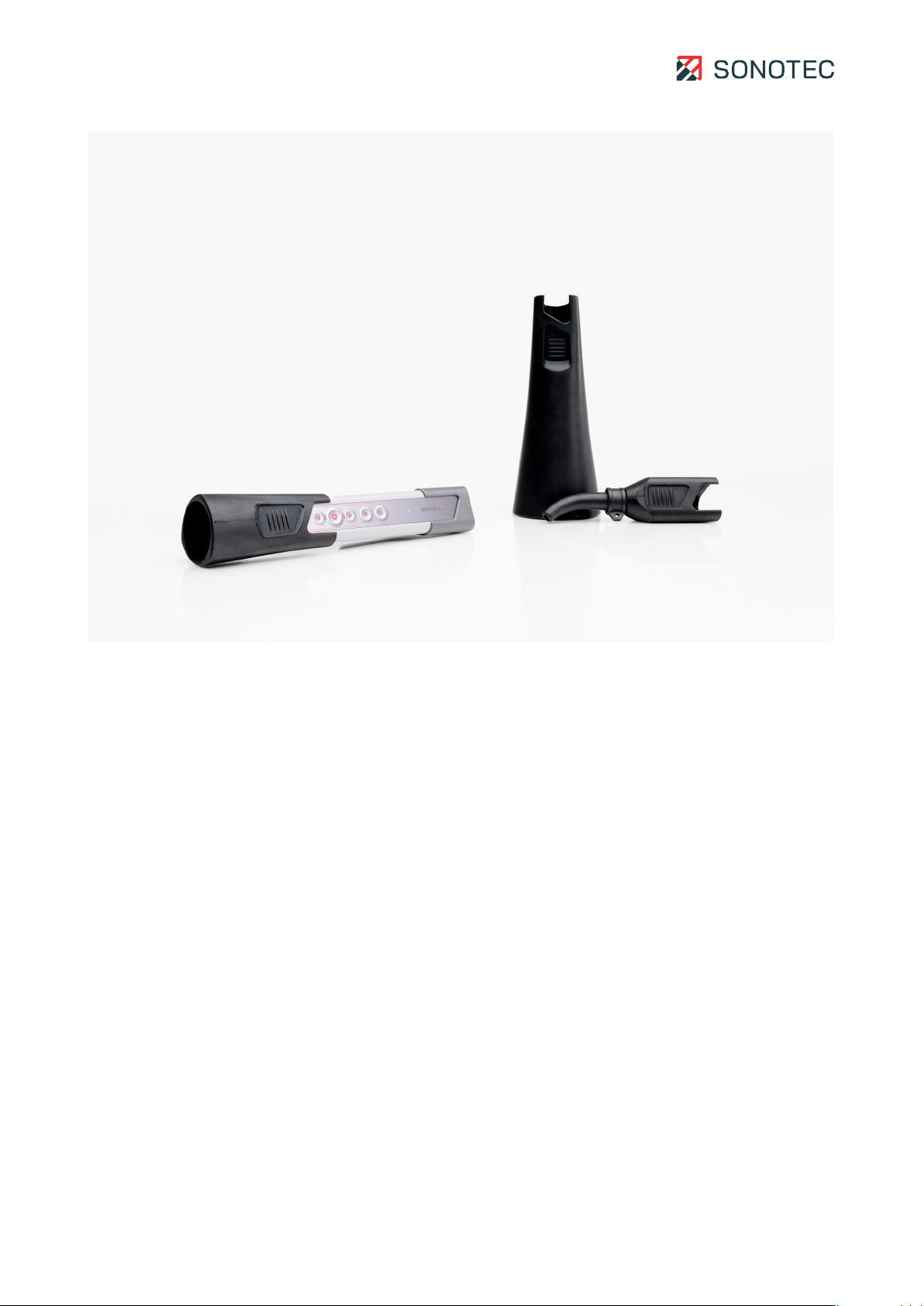
3.6.1 Small acoustic horn BS10-2.............................................................................13
3.6.2 Large acoustic horn BS10-3 ............................................................................14
3.6.3 Precise locator BS10-1 .....................................................................................14
4Operation of the sensor .................................................................................................. 15
4.1 Assembling or disassembling the sensor attachments ............................................ 15
4.2 Connecting the sensor ................................................................................................. 16
4.3 Operation via sensor buttons....................................................................................... 17
5Cleaning and maintenance ............................................................................................. 18
5.1 Cleaning.......................................................................................................................... 18
5.2Maintenance .................................................................................................................. 18
6Technical data ................................................................................................................. 19
7Disposal ........................................................................................................................... 21
8Warranty ..........................................................................................................................22
9Manufacturer information.............................................................................................. 23

Operating Manual | 1 Introduction
BS10
3 / 23
Revision: 2.1 | 2023-04-27
1Introduction
This section is intended to explain function, structure and representations of this
documentation to simplify handling of this documentation.
1.1 Notes on this documentation
Purpose
This documentation constitutes an integral part of the product and contains important
advice on safe operation as well as all information on intended and efficient use. Thus, any
person using the product must have read and understood this documentation.
Accessibility
The staff working with this product must have constant access to this documentation to
prevent handling errors and guarantee trouble-free operation.
Up-to-dateness
Every effort has been made to ensure that the information contained in this documentation
is complete and correct at the time of release. This documentation describes all units and
functions known at the current point of time.
1.2 Representations in this documentation
Illustrations
Illustrations used in this documentation do not always contain all details or special cases.
They only represent the relevant information.
Tips
Tips are marked as follows:
Tips describe specific information or particular features that might not be evident, even
for experienced users. The neglect of a tip poses no direct safety risk. However, it can
lead to workflow disruptions.
General icons
The following general icons are used for visual emphasis:
Icon Function
Indicates a link to external content.

Operating Manual | 1 Introduction
BS10
4 / 23
Revision: 2.1 | 2023-04-27
1.3 Identification of warning instructions
Classes of danger, signal words and colors
This documentation contains warnings regarding hazards of different classifications. These
classes are characterized by signal words and colors. They include the following:
WARNING
Warns of possible immediate danger, which, if ignored, may lead to lasting damage to
health and/or property – including financial losses due to operational impairment.
ATTENTION
Warns of dangers, which, if ignored, may lead to damage to property – including damage
to property due to operational interruptions.

Operating Manual | 2 Safety instructions
BS10
5 / 23
Revision: 2.1 | 2023-04-27
2Safety instructions
This section contains safety information relating to the protection of persons as well as safe
and fault-free operation. All user groups of the product must be aware of and follow these
safety provisions.
2.1 Introduction
Reliable and safe operation of the product depends on the careful handling and execution of
operational and setting tasks.
Ignoring these safety instructions and warning information may lead to serious injury with
lasting health consequences for personnel as well as damage or destruction of product
components.
During handling of the product, please observe all safety instructions and warning
information in all parts of this user documentation as well as the related codes of practice.
Ensure that all those working with the product are also aware of these instructions.
Generally applicable safety regulations (such as accident prevention and environmental
protection regulations, etc.) must also be observed.
2.2 Basic hazards
Definition
Basic hazards are residual risks that remain even with safety-conscious intended use.
State of the art
The product meets the current state of the art and applicable safety rules. All components
of the product are tested thoroughly before they leave the factory and are delivered in a
condition for safe operation.
WARNING
Danger of injury!
Improper use of the product may lead to injuries.
• Do not open the product.
• Protect the product against extreme heat (excessive sunlight, immediate vicinity of
open fire or heating devices) during operation and storage.
• Avoid strong impacts that could damage the device and/or its components.

Operating Manual | 2 Safety instructions
BS10
6 / 23
Revision: 2.1 | 2023-04-27
2.3 Personnel and qualifications
Basic requirements
The product must only be used by operators that have completely read and understood the
safety instructions and all documents of the user documentation.
Personnel undergoing training or instructions or persons taking part in general vocational
training programs may only operate the device under the continuous supervision of
operating or technical personnel.
Responsibility of the operating company
Regarding the personnel authorized and/or trained by the operating company, the operating
company carries the following responsibilities:
• The necessary training and instruction of personnel must be guaranteed.
• All personnel's competences and responsibilities must be clearly stated and
documented.
• All user information on the product (operating manual, user documentation etc.) must
be kept in the immediate vicinity of the product and must be accessible at all times.
2.4 Safety-conscious working practices
Accident prevention and environmental protection
In addition to the instructions in this operating manual, please mind the generally applicable
legal and other regulations on accident prevention and environmental protection.
This may include, for example:
• Handling of hazardous materials
• Wearing the required and mandatory personal protective clothing and safety
equipment
• Observing of and complying with all national and regional industrial safety regulations
• Observing of and complying with all internal working, operating and safety regulations

Operating Manual | 2 Safety instructions
BS10
7 / 23
Revision: 2.1 | 2023-04-27
2.5 Use of the product
Measures for personal safety
Improper use of the product may lead to injuries of operating personnel.
• During detection of ultrasonic signals on electrical equipment, make sure to keep the
mandatory safety distance from detected electrical defects.
• Always make sure that both hands are free for self-protection, if necessary.
• Always make sure to keep your hands, the product and/or connected equipment within
your field of vision.
• Use the torchlight functionality (LED light) of the product and/or additional lighting to
illuminate test sites with poor visibility.
• Always use the product without distraction. Do not read messages on the display
and/or operate the product while walking.
Measures for protection of the product and/or equipment
Improper use of the product may lead to product damage. Damaged components may affect
or distort the measurement result quality.
• During use, charging and storage, protect the device against extreme, unusual heat
(excessive sunlight, storage in heated cars or immediate vicinity of open fire or heating
devices). It is critical to stay within the temperature ranges given in the technical
specification.
• Do not use the product and its accessories if they display functional errors and/or
visible damage.
• Only connect the product to approved equipment received from SONOTEC GmbH or
its sales partners.
• The product adheres to the protection class given in the technical specification and is
not protected against water. Do not submerge the product in liquids. Protect the
product against moisture penetration.
• Handle the product with care and protect it against major shocks.
• When using the product, always make sure that cables cannot get stuck and/or caught
in moving parts.
• Do not use the product within strong electromagnetic fields.

Operating Manual | 2 Safety instructions
BS10
8 / 23
Revision: 2.1 | 2023-04-27
2.6 Modifications and alterations
No modifications on the product and/or accessories
The product and/or its accessories must not be opened or disassembled. The product does
not contain any components to be cleaned, maintained or repaired by operators.
Unauthorized modifications of the product and/or its accessories are prohibited and lead to
exclusion of liability by the manufacturer for resulting damage and consequences.
Spare parts and accessories
Spare parts and accessories must comply with the technical requirements specified by
SONOTEC GmbH and its suppliers. Whenever original parts are used, compliance is given.

Operating Manual | 3 Description of the sensor
BS10
9 / 23
Revision: 2.1 | 2023-04-27
3Description of the sensor
This section describes use, function, structure and accessories of the sensor.
3.1 Intended use
The Broadband airborne sound sensor BS10 is used for air-borne sound detection in the
ultrasonic range. Used in connection with the SONAPHONE digital ultrasonic testing device
and multiple equipment, the sensor has been designed for the following test tasks:
• Detection and evaluation of leaks in compressed air, gas and vacuum systems
• Detection of electrical partial discharge and insulation damage
• Tightness testing of windows, doors, cabins, vehicles or containers (in combination
with the SONAPHONE T ultrasonic transmitter)
The sensor's function keys may be used for starting and stopping measurement value
recordings and to control the acoustic playback volume. An integrated class 2 target laser
and a LED light support locating test sites.
3.2 Prohibited use
Any use not approved by SONOTEC GmbH is prohibited and may lead to injury or damage to
property.
SONOTEC GmbH accepts no liability for damage caused by prohibited use of the product.
Prohibited are in particular:
• Use of equipment and/or accessories with visible damage
• Use in wet rooms
• Use in potentially explosive environments
• Use in environmental conditions that do not adhere to the stipulated requirements
• Unauthorized modifications of the equipment, the software and/or accessories
• Use of unauthorized spare parts and/or unauthorized accessories
Operating Manual | 3 Description of the sensor
BS10
10 / 23
Revision: 2.1 | 2023-04-27
3.3 Working principle
The sensor attachments guide the ultrasound to the ultrasonic microphone.
The sensor's ultrasonic microphone converts sound pressure fluctuations in the air to an
electrical signal over a wide frequency range. This electrical signal is amplified and
digitalized within the sensor. Further data processing and output takes place in the testing
device.
The target laser helps with precisely locating damaged areas:
If the sensor points towards the damaged area during the search, the precise location may
be detected by means of acoustic signals, by pivoting the sensor and searching for a local
maximum sound level. The target laser marks the approximate position of the damaged
area.
The LED light serves as a torch light, making it easier to search for damaged areas in poorly
lit environments.
3.4 Sensor construction
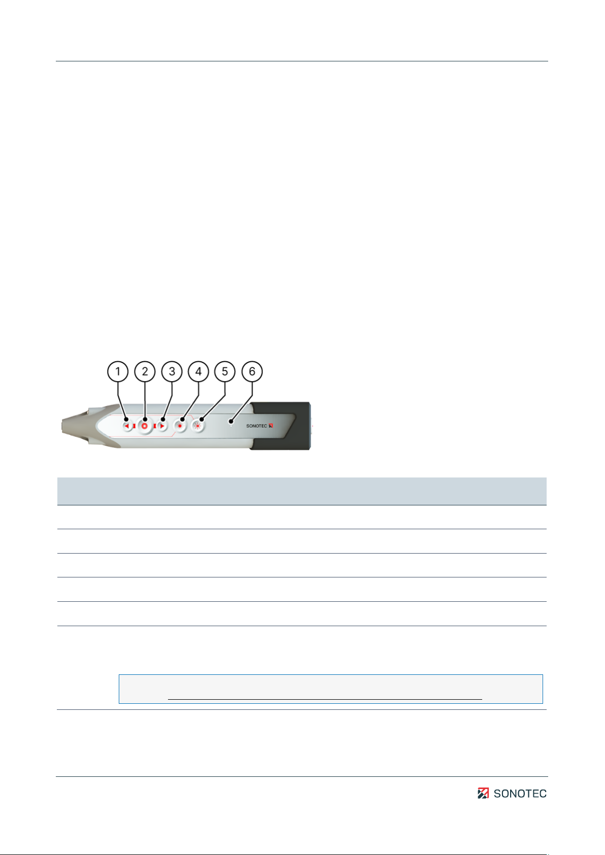
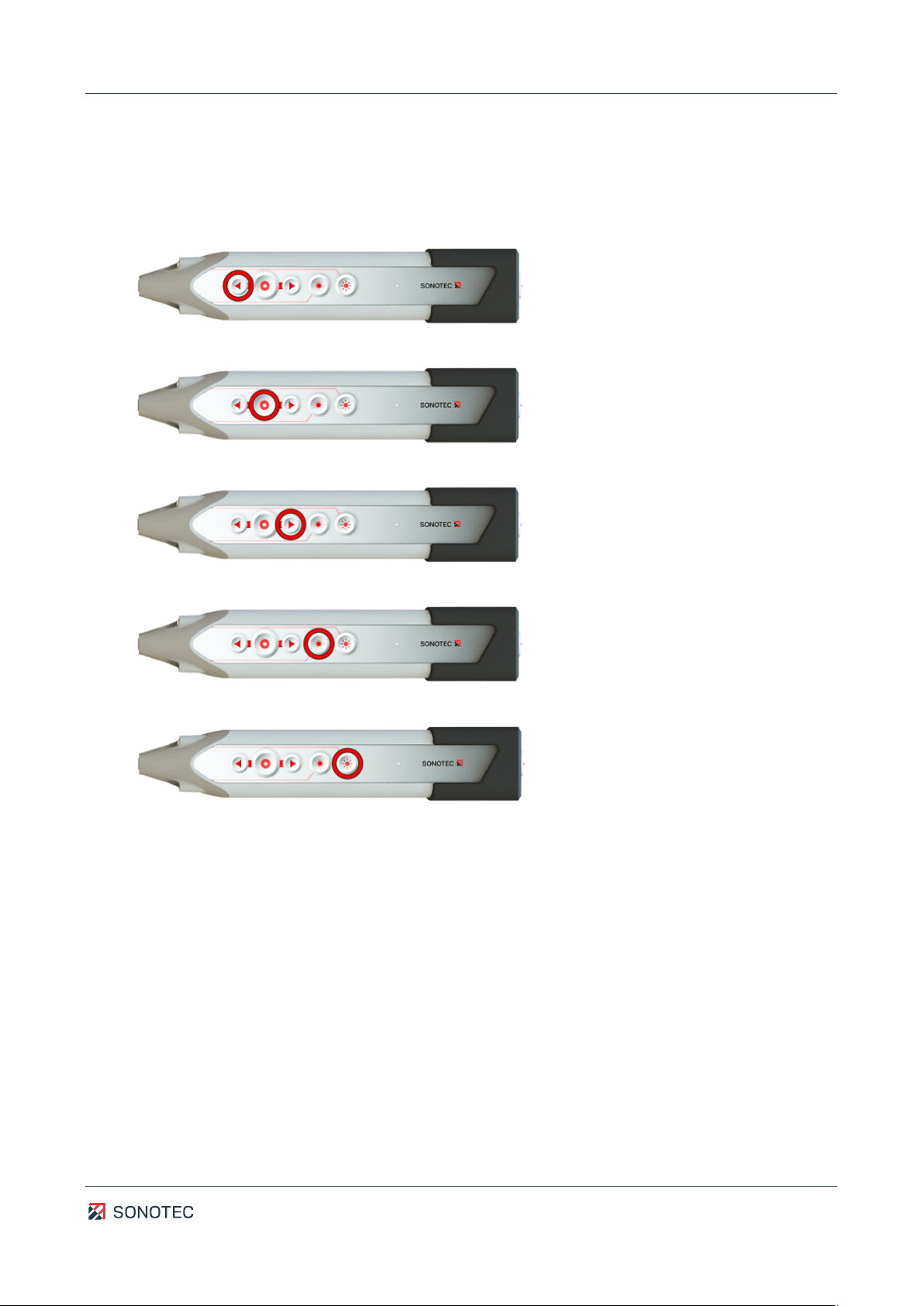
Operating elements
Figure 1: Operating elements of the BS10
No. Description/function
1 Increases the volume of the acoustic playback.
2 Starts/stops a measurement value recording.
3 Decreases the volume of the acoustic playback.
4 Switches on the target laser (keep the button pressed)
5 Switches the LED light (torch light) on or off
6 Status LED
• Constantly lit: sensor is activated
• Flashing: sensor is in boot mode
Boot mode is required for sensor firmware updates.
(see Updating sensor firmware with the SONAPHONE Hardware Manager app)
Operating Manual | 3 Description of the sensor
BS10
11 / 23
Revision: 2.1 | 2023-04-27
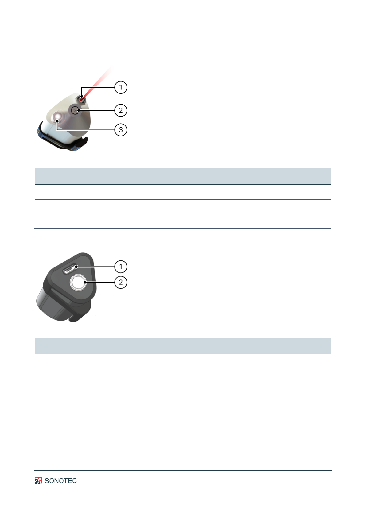
Sensor elements
Figure 2: Sensor elements of the BS10
No. Description/function
1 Target laser (laser class 2)
2 Ultrasonic microphone
3 LED light (torch light)
Connections
Figure 3: Connections of the BS10
No. Description/function
1 USB port
• Type: Micro-USB socket, type B
• for service purposes only
2 Sensor cable socket
• Type: LEMO 0B (4-pin)
• with marked plug-in position
Operating Manual | 3 Description of the sensor
BS10
12 / 23
Revision: 2.1 | 2023-04-27
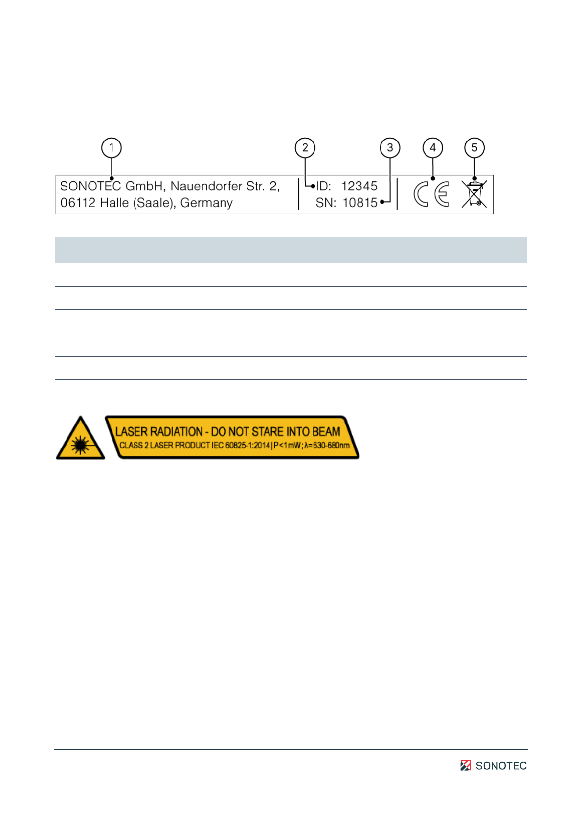
3.5 Sensor identification
Identification plate
Figure 4: Identification plate with its components
No. Identification
1 Manufacturer’s address
2 Sensor ID
3 Serial number
4 CE marking
5 Disposal symbol (see "7 Disposal", page 21)
Laser class identification
Operating Manual | 3 Description of the sensor
BS10
13 / 23
Revision: 2.1 | 2023-04-27
3.6 Accessories
Intensity and behavior of ultrasonic signals depend on factors such as the process during
which they are generated. Measurement value recordings with high signal quality are
necessary for valid conclusions on system conditions. Signal quality also depends on a
number of factors.
In order to guide high-quality signals to the sensor's ultrasonic microphone, the following
attachments are available for different applications.
3.6.1 Small acoustic horn BS10-2
Application For close-range detections
Article number 400 01 0145
Description
The small acoustic horn BS10-2 is used as the standard attachment on BS10. This
attachment provides the sensor with a directivity for close-range applications. A relatively
large opening angle allows for simple detection of ultrasound sources in the room. Use the
target laser to narrow down the area for subsequent precise location.

Operating Manual | 3 Description of the sensor
BS10
14 / 23
Revision: 2.1 | 2023-04-27
3.6.2 Large acoustic horn BS10-3
Application For detections within a range of up to 8 m
Article number 400 01 0148
Description
The large acoustic horn BS10-3 increases the directivity of the sensor compared to the
small acoustic horn BS10-2. The opening angle decreases while the sensitivity increases.
This means detection of ultrasound sources becomes possible for larger distances.
Background noise of other ultrasound sources within the room can easily be distinguished
from the sound source to be detected. Use the target laser to narrow down the area for
subsequent precise location.
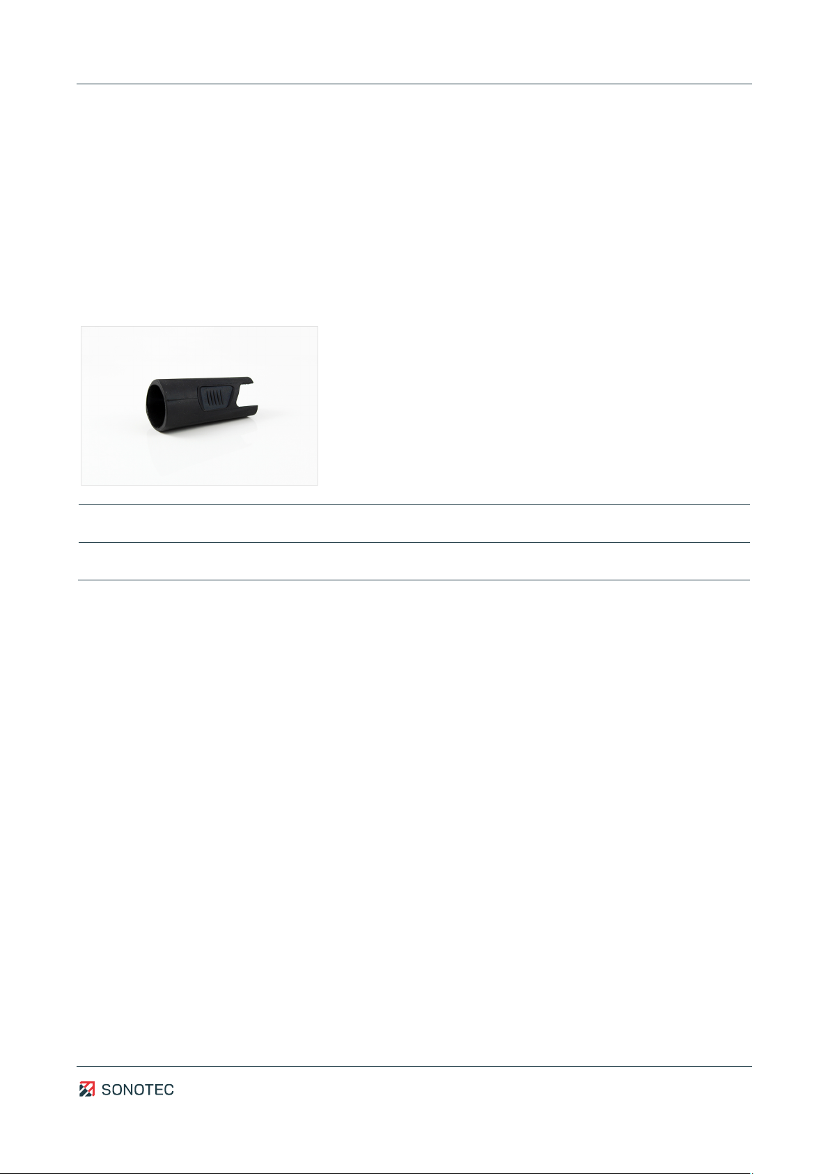
3.6.3 Precise locator BS10-1
Application For precisely locating ultrasound sources
Article number 700 01 0296
Description
The precise locator BS10-1 directs the sensitive opening of the sensor to a small circular
area. This means that wide range and directivity are lost. In return, it is possible to search
for an ultrasound source directly on the surface of a test object. For detection, the tip may
be turned in the direction of the damaged area. Thus, it is possible to differentiate between
sound sources that are close to each other and to identify defective components.

Operating Manual | 4 Operation of the sensor
BS10
15 / 23
Revision: 2.1 | 2023-04-27
4Operation of the sensor
This section contains descriptions and instructions for operating the sensor and using it in
combination with the SONAPHONE handheld unit.
WARNING
Risk of injury to eyes by target laser!
The target laser (laser class 2) can cause serious eye damage.
• Never look into the laser beam.
• Never direct the laser at other people or vehicles.
• Keep in mind that in the event of ongoing exposure, even reflected laser light might
cause eye injuries.
4.1 Assembling or disassembling the sensor attachments
ATTENTION
Risk of faulty readings due to wrongly installed sensor attachments!
Crooked or loosely mounted sensor attachments may lead to faulty readings and/or
influence the directivity characteristics of the target laser.
• Always make sure to mount the sensor attachments securely in a tight and straight
manner.
Mounting
1. Hold the sensor with one hand and move the sensor attachment on the sensor with the
other hand until the sensor attachment perceptibly locks in place.
Removal
1. Hold the sensor with one hand and pull the sensor attachment from the sensor with
the other hand.
Operating Manual | 4 Operation of the sensor
BS10
16 / 23
Revision: 2.1 | 2023-04-27
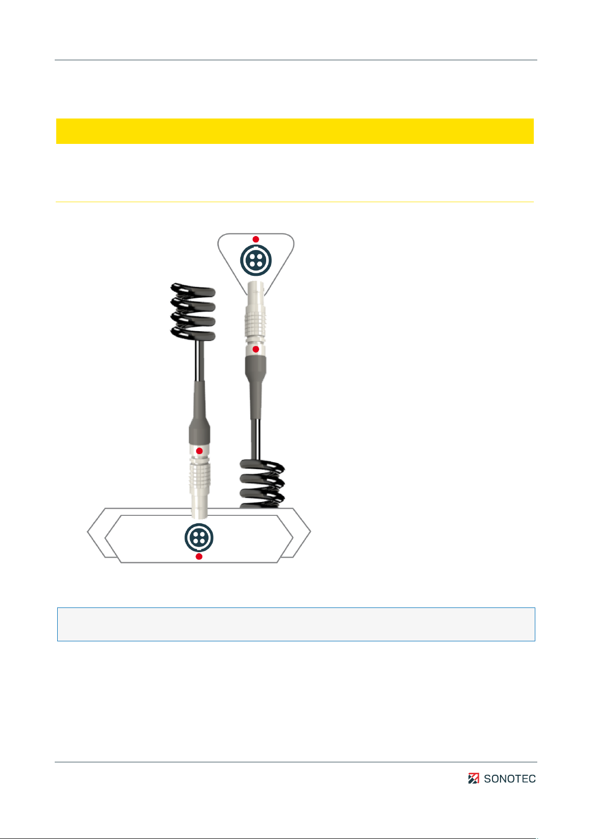
4.2 Connecting the sensor
ATTENTION
Risk of damage to sensor and/or sensor cable!
When connecting the sensor, always mind the red markings on the sockets of the sensor
and the SONAPHONE handheld unit as well as the sensor cable.
1. Connect the sensor to the SONAPHONE handheld unit via the sensor cable.
The SONAPHONE handheld unit provides power to the sensor.
As soon as the status LED of the sensor is constantly lit, the sensor is ready for use.
During measurements, the measurement data will be transferred automatically from the
sensor to the SONAPHONE handheld unit.
Operating Manual | 4 Operation of the sensor
BS10
17 / 23
Revision: 2.1 | 2023-04-27
4.3 Operation via sensor buttons
Measurements may be controlled either via the touch screen of the SONAPHONE handheld
unit or the sensor buttons. The sensor buttons provide the following functions:
• Increasing the acoustic playback volume
• Starting or stopping the measurement value recording
• Decreasing the acoustic playback volume
• Switching on the target laser (keep the button pressed)
• Switching the LED light on or off

Operating Manual | 5 Cleaning and maintenance
BS10
18 / 23
Revision: 2.1 | 2023-04-27
5Cleaning and maintenance
5.1 Cleaning
Guidelines
Do not open the product! The product contains no parts to be cleaned by the operator.
ATTENTION
Risk of damage of the ultrasonic microphone!
The ultrasonic microphone may be damaged during sensor cleaning.
• Do not let detergent enter the ultrasonic microphone.
• Avoid mechanical stress on the ultrasonic microphone.
Suitable cleaning products
Only clean the product on the outside with soft, lint-free cloth.
ATTENTION
Check the compatibility of used cleaning agents!
The compatibility of all cleaning agents with used materials and colors must be confirmed
and approved by SONOTEC GmbH or the respective supplier.
Unsuitable cleaning agents
Do not clean the product with:
• scratchy, aggressive, solvent-containing or benzine-containing cleaning agents,
• pressured air, high-pressure cleaner or other kinds of cleaning machine.
After cleaning
After cleaning the device, make sure that:
• cables, connectors and fittings are free of cleaning agents and
• cables, wires, connectors and electrical components are dry.
5.2 Maintenance
Guidelines
Do not open the device! The device contains no parts to be maintained or repaired by the
operator.

Operating Manual | 6 Technical data
BS10
19 / 23
Revision: 2.1 | 2023-04-27
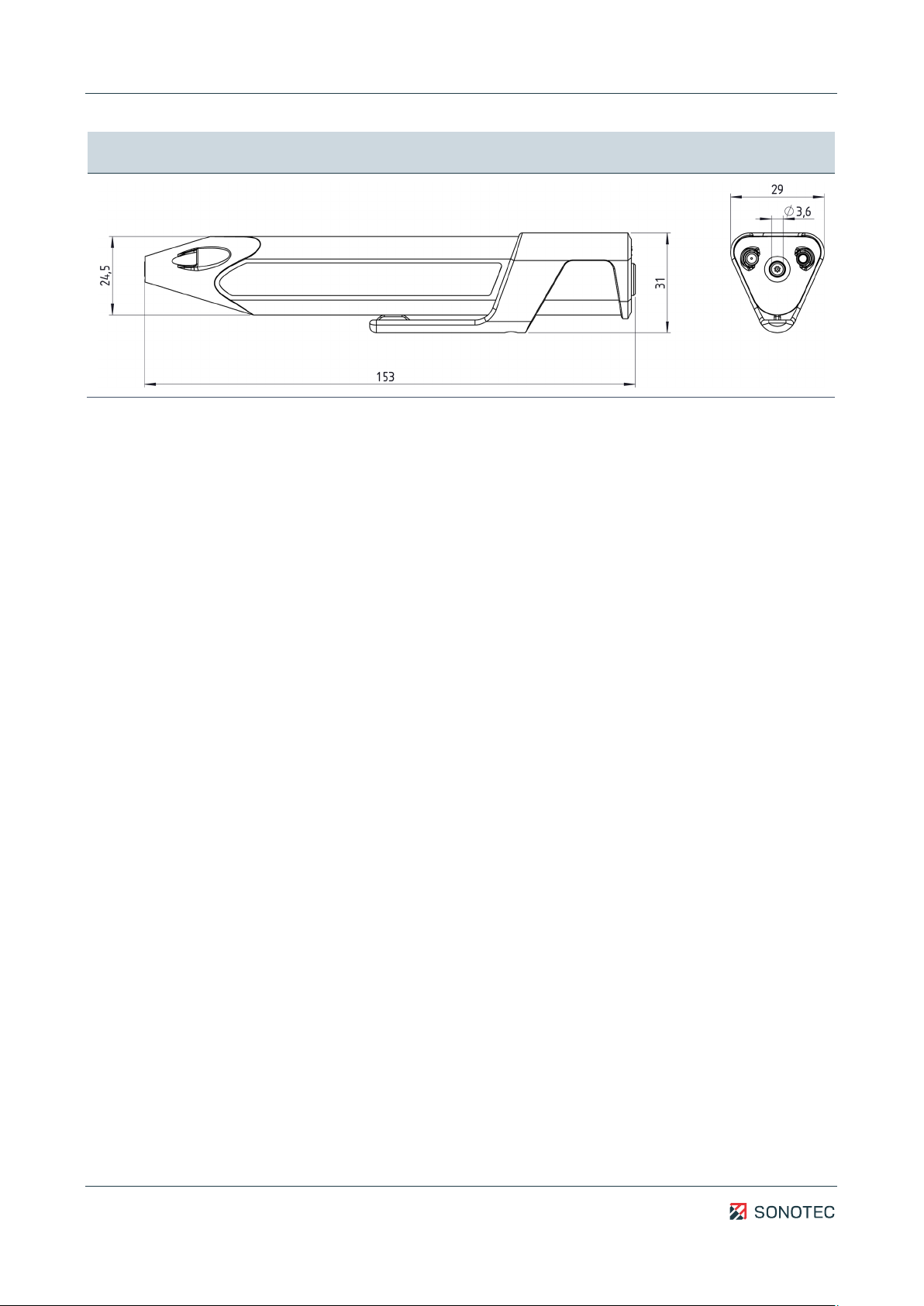
6Technical data
General data
Article number 200 01 0299
Dimensions (L × W × H) see technical drawing
Weight 80 g (without accessories)
Electrical connection LEMO 0B (4-pole)
Acoustic data
Frequency range 15 … 100 kHz
Measurement resolution 1 dB
Materials
Housing material Polycarbonate/ABS
Ambient conditions
Operating temperature -10 … +65 °C
(according DIN EN 60068-2-2:2008-05)
Storage temperature -20 … +65 °C
(up to 40 °C at 90 % humidity according to DIN EN 60068-
2-78:2014-02)
Protection type IP40
Order details
Scope of delivery • Broadband airborne sound sensor BS10
• Calibration certificate
Operating Manual | 6 Technical data
BS10
20 / 23
Revision: 2.1 | 2023-04-27
Technical drawing
Other manuals for Airborne Sound Sensor BS10
1
Table of contents
Other Sonotec Accessories manuals


