Sonotec SONAPHONE BS20 Operator's manual

Ultrasonic Testing Device for Preventive Maintenance
User Documentation:
Structure-Borne Sound Sensor BS20

© SONOTEC Ultraschallsensorik Halle GmbH
All rights reserved.
Revision: 1.0; Date: 2017-11-06
Subject to technical modifications!
Structure-Borne Sound Sensor BS20
II - II - 3
Revision: 1.0; Date: 2017-11-06
Content
1Information on this document.............................................................................................................. 5
1.1 General...........................................................................................................................................5
1.2 Symbols used.................................................................................................................................6
2Sensor description................................................................................................................................ 7
2.1 Applications and designated use ...................................................................................................7
2.2 Functioning.....................................................................................................................................7
2.3 Connections, operating and display elements ...............................................................................8
2.4 Accessories for the structure-borne sound & temperature sensor BS20 ....................................10
2.5 Device identification/type label.....................................................................................................11
3Sensor operation................................................................................................................................. 12
3.1 Connecting the sensor .................................................................................................................12
3.2 Assembling and disassembling waveguides................................................................................13
3.3 Using the waveguides..................................................................................................................14
3.4 Operation via the buttons on the sensor......................................................................................14
3.5 Temperature measurements........................................................................................................15
3.6 Cleaning and maintenance ..........................................................................................................15
4Disposal................................................................................................................................................ 16
5Warranty............................................................................................................................................... 17
Structure-Borne Sound Sensor BS20
II - II - 4
Revision: 1.0; Date: 2017-11-06
(This page has been deliberately left empty)
Structure-Borne Sound Sensor BS20
II - II - 5
Revision: 1.0; Date: 2017-11-06
1 Information on this document
1.1 General
This document forms part of the structure-borne sound sensor BS20 and should therefore be
stored in its immediate vicinity where it can be accessed by all operators at any time. It contains
all the instructions to ensure safe operation of the structure-borne sound sensor with the
SONAPHONE, as well as all the information needed to ensure proper and efficient use. It must
therefore be read prior to first use and before carrying out any further steps.
The structure-borne sound sensor BS20 must only be operated by users
who have read (in full) and understood the safety information in the
corresponding document and the provided user documentation.
This document has been created with all due care. SONOTEC does not assume any guarantee
of the completeness, correctness and current validity of the provided data and is not liable for
errors or omissions.
Please note that the user documentation for the SONAPHONE is made up of different sections
due to the device's modular construction. The scope of supply will vary depending on the device
and accessory options that have been ordered.

Structure-Borne Sound Sensor BS20
1 Information on this document
II - II - 6
Revision: 1.0; Date: 2017-11-06
1.2 Symbols used
Hazards or special information are indicated in the following ways:
Warns of possible imminent dangerswhich, if ignored, may lead to
lasting adverse health effects and/or serious material damage.
Warns of dangers which, if ignored, may lead to injury and/or material
damage - including financial losses due to operational interruptions.
Warns of dangers which, if ignored, may lead to material damage –
including financial losses due to operational interruptions.
Note
This section provides information or draws attention to special features.

Structure-Borne Sound Sensor BS20
II - II - 7
Revision: 1.0; Date: 2017-11-06
2 Sensor description
2.1 Applications and designated use
The structure-borne sound sensor with exchangeable waveguides is used for applications
including:
Status monitoring of machines, systems and plant components
Function checking of steam traps and valves
Monitoring of wear and malfunctions in bearings
Monitoring of lubrication conditions
2.2 Functioning
The waveguide conducts the ultrasonic waves from the test point to the ultrasonic transducer.
The ultrasonic transducer converts ultrasonic waves (vibrations) to an electrical signal over a
wide frequency range. This electrical signal is amplified and digitalized within the sensor.
Further data processing and output takes place in the testing device.
The integrated infrared temperature sensor allows for contactless and quick recording of the
test object's surface temperature. The size of the visual recording field depends on the distance
between the sensor and the test object.
The LED lights act as a torch, making it easier to connect the sensor to test points in poorly lit
environments.

Structure-Borne Sound Sensor BS20
2 Sensor description
II - II - 8
Revision: 1.0; Date: 2017-11-06
2.3 Connections, operating and display elements
No. Operating and display elements
1 Sensor accessory: Short waveguide (standard)
2 Adjusting the volume
3 Starting/stopping the measurement recording
4 LED lights (torch) on/off
5 Status LED
3
4
2
5
1

Structure-Borne Sound Sensor BS20
2 Sensor description
II - II - 9
Revision: 1.0; Date: 2017-11-06
No. Sensor elements and connections
1 LED lights (torches)
2 Ultrasonic transducer – coupling surface (internal thread M5)
3 Infrared temperature sensor
No. Connections
1 USB connection (for service work only)
2 Socket for sensor cable with marked plug-in position
1
2
3
1
2
Structure-Borne Sound Sensor BS20
2 Sensor description
II - II - 10
Revision: 1.0; Date: 2017-11-06
2.4 Accessories for the structure-borne sound & temperature sensor BS20
The intensity and behavior of ultrasonic signals depend on factors such as the process during
which they are generated. Options for verifying and recording the signals and for providing
these to the user in high-quality format so that useful statements can be made with regard to
system conditions are also dependent upon a number of different factors.
In order to record high-quality signals for processing in the structure-borne sound & temperature
sensor BS20, waveguides are available for different testing tasks.
In order to ensure optimal results, please observe the fields of application for the accessories as
well as the corresponding instructions.
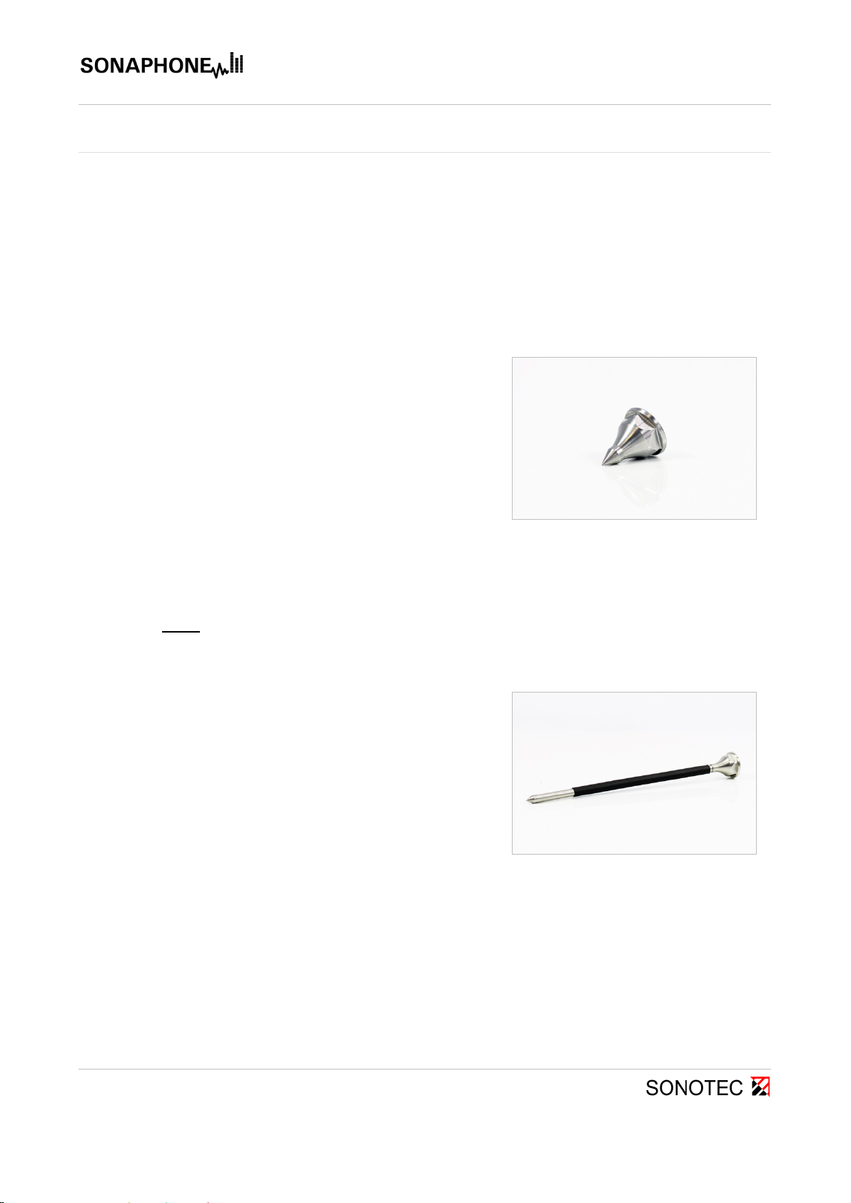
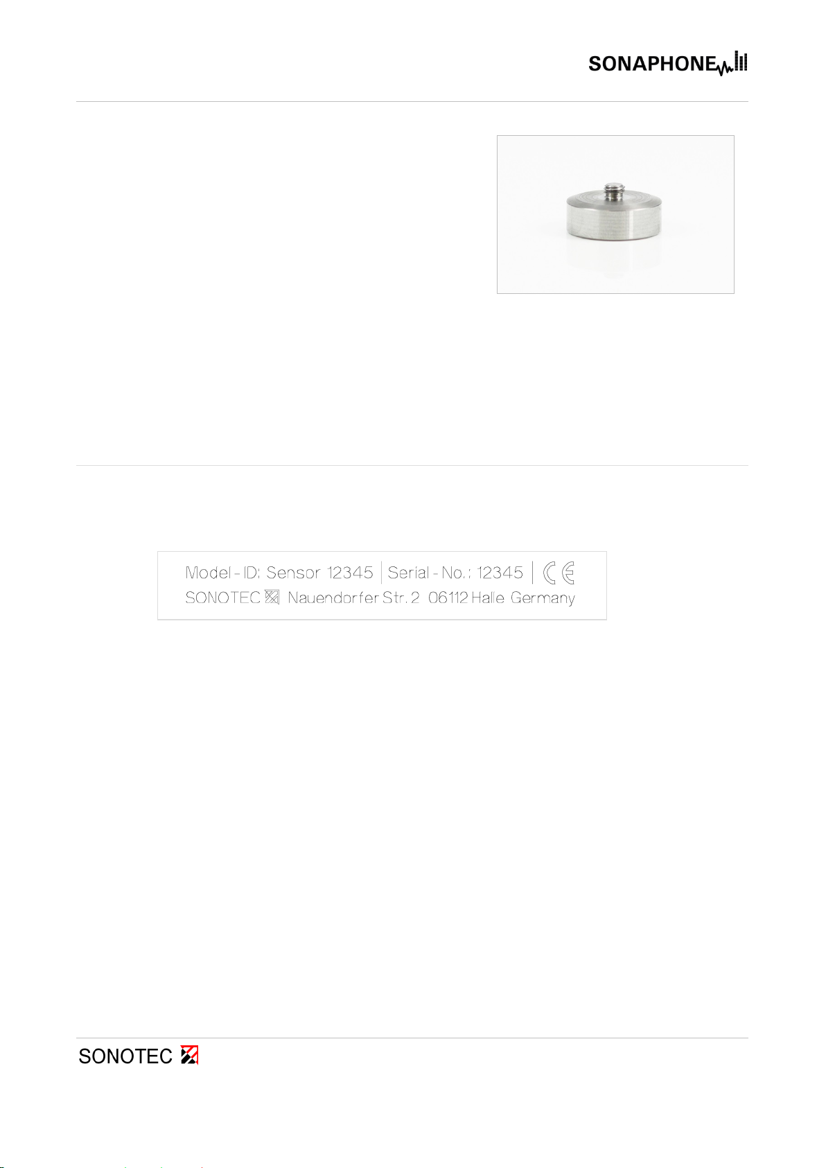
Short waveguide BS20-1
Accessory for structure-borne sound and temperature
sensor BS20 (standard)
Fig. 1: Short waveguide BS20-1
The waveguide is used to record ultrasonic waves that spread in solid structures, and to pass
these on for processing in the sensor. Sufficient contact pressure is required in order for this to
work correctly.
Note: For comparable results, sound should always be recorded from the same position. It may
be useful to attach a punch point at the required position.
Long waveguide BS20-2
(optional)
Accessory for structure-borne sound and temperature
sensor BS20
Application:
Tests on hard-to-access points
Fig. 2: Long waveguide BS20-2
This waveguide, which is longer than the BS-20-1, makes it possible to reach test points that
are harder to access. The long waveguide also makes it possible to carry out tests on hot
surfaces.
The signals will be slightly modified as a result of the longer sound path, and this will need to be
taken into account in the evaluation.
Structure-Borne Sound Sensor BS20
2 Sensor description
II - II - 11
Revision: 1.0; Date: 2017-11-06
Magnetic waveguide BS20-3
(optional)
Accessory for structure-borne sound and
temperature sensor BS20
Application:
For connection at the test point for long-term testing
and for ensuring even contact pressure
Fig. 3: Magnetic waveguide BS20-3
In order to ensure usable test results with long-term testing or comparative tests, even contact
pressure is required. This can be achieved using the magnetic waveguide. Following connection
to the test point, the magnetic coupling ensures even recording of ultrasonic signals.
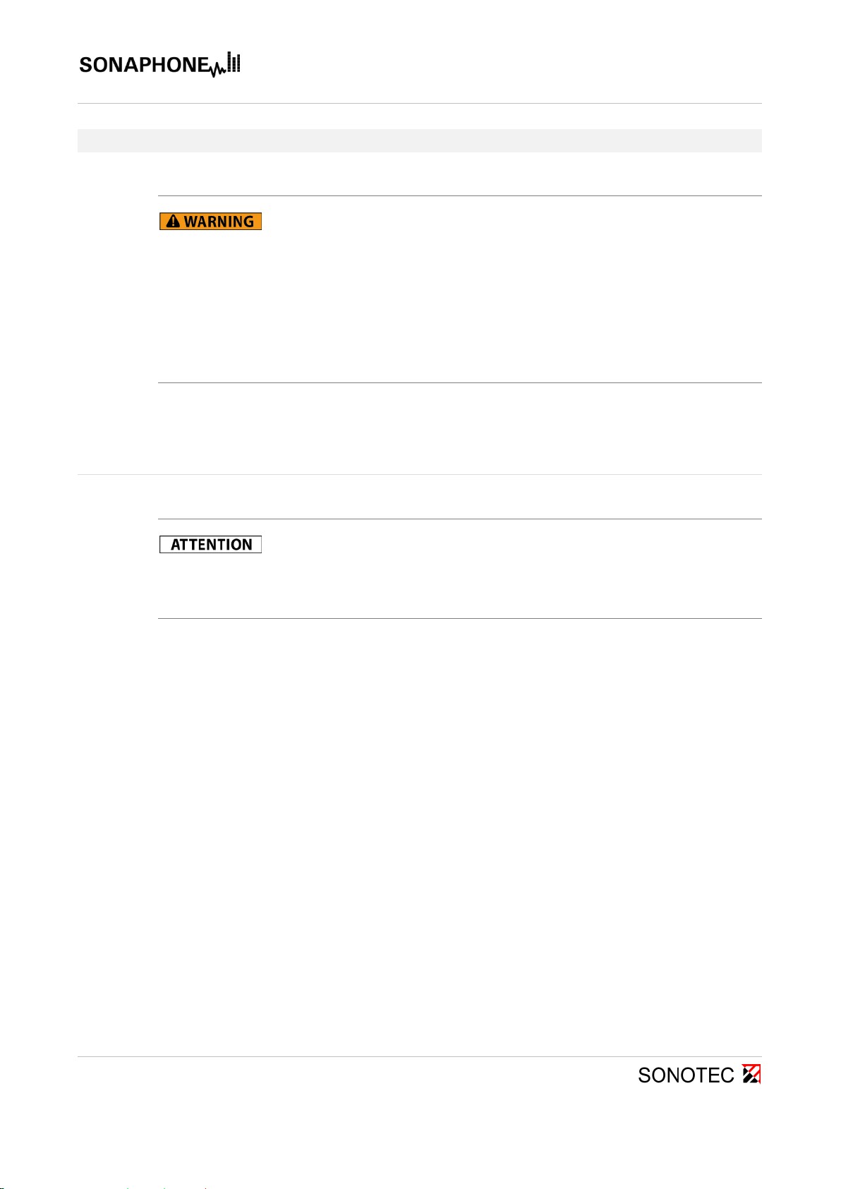
2.5 Device identification/type label
The type label is located on the back of the device, and should be to hand in the event of a
service call. As well as the sensor designation, the following information can also be found on
the housing:
Structure-Borne Sound Sensor BS20
II - II - 12
Revision: 1.0; Date: 2017-11-06
3 Sensor operation
Danger of injury!
•The sharp ends of the waveguides can cause injuries, and even serious
injuries in the case of the long waveguide. Make sure never to injure
anyone with the sharp ends of the waveguides. Never direct the tip at
other people.
•The high magnetic force of the waveguide can lead to crushing injuries
to the hands. Place the magnetic waveguide onto the test object at an
incline and as slowly as possible.
3.1 Connecting the sensor
Risk of damage to the connectors!
Take note of the red dots indicating the plug-in position on the plug and
socket.
Connect the sensor to the SONAPHONE in accordance with the red dots, making sure to
use the designated cable.
The sensor is powered via the cable, and the test data is transferred to the SONAPHONE
automatically.
The sensor is ready for operation when the operating display LED lights up green.
Structure-Borne Sound Sensor BS20
3 Sensor operation
II - II - 13
Revision: 1.0; Date: 2017-11-06
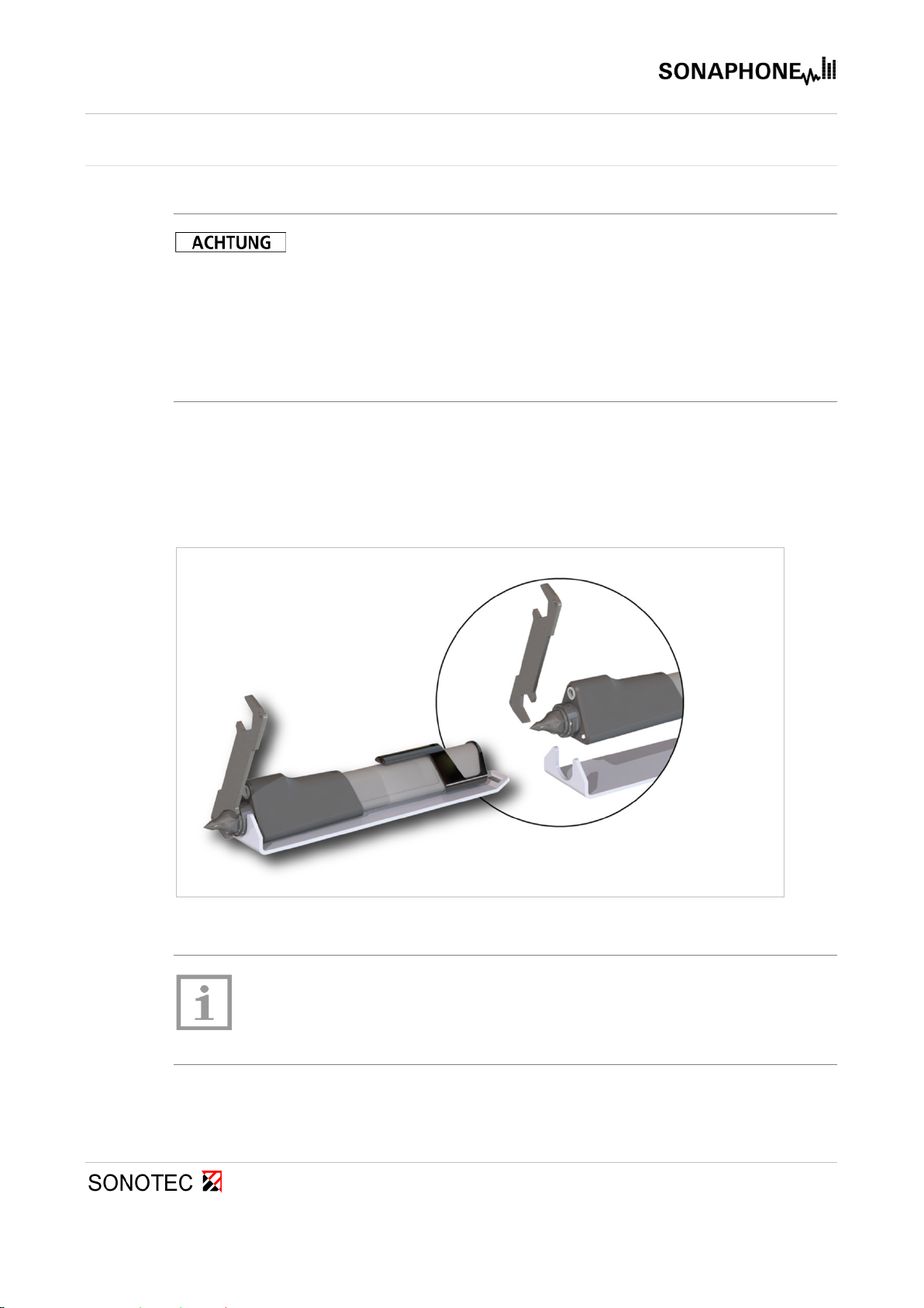
3.2 Assembling and disassembling waveguides
Risk of device damage and incorrect test values!
•Risk of destruction of the waveguide holder as a result of incorrect
assembly and disassembly. Always use the two elements of wrench set
BS20 (see image below) to assemble and disassemble the waveguides.
•Make sure that the waveguides are securely screwed into the holder.
The ultrasound is guided to the ultrasonic transducer by the waveguides.
Loose waveguides may have an impact on the signals.
The screw thread in the waveguide holder is used to attach the sensor accessory parts onto the
sensor shaft. The wrench set BS20 prevents damage when screwing the waveguides on and
off.
Fig. 4: Assembly and disassembly of the waveguides using the wrench set BS-20
Note!
The warranty will become invalid in the event of damage due to removing
the waveguides without the wrench set BS20.
!

Structure-Borne Sound Sensor BS20
3 Sensor operation
II - II - 14
Revision: 1.0; Date: 2017-11-06
3.3 Using the waveguides
During testing, the sensor should be pressed against the object being tested in as vertical a
position as possible and using gentle, even pressure.
Fig. 5: Optimal contact angle for testing with waveguides
3.4 Operation via the buttons on the sensor
Measurements can be controlled via the touchscreen on the device or via the buttons on the
sensor itself.
The acoustic playback volume can be adjusted using the function buttons. Testing can also be
started and stopped. The LED lights (torches) also help with the precise location of damage
areas.
The internal thread on the sensor and the magnetic waveguide BS20-3 make it possible to carry
out quasi-stationary tests using the SONAPHONE.
90°

Structure-Borne Sound Sensor BS20
3 Sensor operation
II - II - 15
Revision: 1.0; Date: 2017-11-06
3.5 Temperature measurements
Note!
For correct temperature measurements, make sure that the surface of the
temperature sensor is free from contamination.
The infrared temperature sensor is calibrated on a black emitter that emits the maximum
possible temperature (100 % emission → emissivity value ε = 1). As the emission
characteristics of the surfaces of measurement objects will deviate from this value, this will need
to be taken into account for the contactless temperature measurement.
Painted or oxidized surfaces usually have an emissivity value of 0.9. This setting is suitable for
many measurement tasks. Additional values for frequently used materials can be found in
emissivity value tables.
The emissivity value can be set at the SONAPHONE as follows:
In the LevelMeter app, under the
Settings Temperature measurement
menu item, a material with a stored emissivity value can be selected, or an emissivity value
specified manually.
3.6 Cleaning and maintenance
The sensor is maintenance-free. It can be cleaned externally using a damp cloth and a mild,
non-abrasive cleaning agent.
D = 38 mm
D = 11 mm
Structure-Borne Sound Sensor BS20
II - II - 16
Revision: 1.0; Date: 2017-11-06
4 Disposal
Electrical and electronic equipment can pose serious health and environmental risks if it is
not properly disposed of. For this reason it must not be disposed of in domestic waste according
to WEEE directive 2012/19/EU (Waste Electrical and Electronic Equipment Directive) but
separately at designated collection points or has to be sent back to the manufacturer.
The following symbol on the device refers to the legal obligation in Germany to arrange a
separate disposal for electronic equipment.
It has to be handled according to specific processes (e.g. concerning the batteries or circuit
boards) to ensure a safe, environmentally-friendly recycling or the separate disposal of different
device components.
The taking back of used equipment is regulated differently in the various countries and regions.
Consult the local authorities and other competent public authorities to inform yourself about the
taking back conditions of commercially used electrical equipment. The device and also the
battery do not contain harmful substances that have to be labelled separately regarding the
disposal as mercury (Hg), cadmium (Cd), lead (Pb) or hexavalent chromium (e.g. in galvanized
parts or circuit boards).

Structure-Borne Sound Sensor BS20
II - II - 17
Revision: 1.0; Date: 2017-11-06
5 Warranty
The ultrasonic testing device and its corresponding sensors comply with the current state of the
art and the safety regulations. All devices and accessory parts are factory tested and are
delivered in a safe condition for operation. We reserve the right to make modifications to the
device as part of ongoing product development, and to make changes to the shape and color.
Within the warranty period, SONOTEC Ultraschallsensorik Halle GmbH will rectify, free of
charge, all defects caused by material or manufacturing errors. At its own discretion, SONOTEC
Ultraschallsensorik Halle GmbH will provide a guarantee in the form of either a repair or the
replacement of the defective device or component. The warranty does not cover the internal
batteries or damage caused by improper use, wear or interventions in the device or sensors.
The warranty also does not cover any defects that have only a negligible impact on the value or
usability of the device.
The recording of valid test results, the interpretation of these results and any measures that are
derived as a result are exclusively the responsibility of the user. SONOTEC does not assume
any guarantee for the correctness of the recorded test values or test results. SONOTEC accepts
no liability for any errors or damages that arise as a result of the further use of the recorded test
and measurement values.

MANUFACTURER
Headquarters
SONOTEC Ultraschallsensorik Halle GmbH
Nauendorfer Str. 2
06112 Halle (Saale)
Phone: +49 (0)345 133 17-0
Fax: +49 (0)345 133 17-99
Email: sonotec@sonotec.de
Internet: www.sonotec.de
USA contact details
SONOTEC US Inc.
190 Blydenburgh rd
Suite 8 2nd floor
Phone: +1 631/415 4758
Email: sales@sonotecusa.com
Internet: www.sonotecusa.com

Technical Data Sheet
V - III - 1
Revision: 1.0; Date: 2017-11-06
Structure-borne sound and temperature sensor BS20
The structure-borne sound sensor BS20 with
exchangeable attachments is used in connection with the
SONAPHONE for applications including:
•Condition monitoring of machines, systems and plant
components
•Function checking of steam traps and valves
•Monitoring of wear and malfunctions in rolling or slide
bearings, for example
•Monitoring of lubrication conditions
The acoustic playback volume can be adjusted using the function buttons. Testing can be sta
rted
and stopped
in the same way. The integrated temperature sensor improves the evaluation
reliability of the test data for a wide range of different test sequences, such as tests on steam traps.
GENERAL SENSOR DATA
Design Contact sensor for the detection of structure-borne sound with exchangeable
waveguides, contactless infrared temperature sensor, LED light
Operation Via buttons on the sensor or on the device
Buttons: Start/stop testing, LED light, volume
Frequency range 20 … 100 kHz
Temperature
measurement range -70 … +380 °C object temperature
Measurement resolution Ultrasound: 1 dB, temperature: 1 K
Power supply and
communication Cable connection with the SONAPHONE (160 cm): LEMO connection
Dimensions (W x H x D) 30 x 155 x 30 mm
Weight 140 g (without accessories)
Materials Sensor housing: plastic (polycarbonate: ABS), gray; waveguides: stainless
steel
AMBIENT CONDITIONS
Operating temperature -10 °C … +40 °C
Storage temperature -20 °C … +60 °C
Protection type IP40

Technical Data Sheet
Structure-borne sound sensor BS20
V - III - 2
Revision: 1.0; Date: 2017-11-06
Standards and
guidelines EMC Directive 2014/30/EU; WEEE Directive 2012/19/EU;
RoHS Directive 2011/65/EU
Accessories
(some of which are
optional)
Short waveguide BS20-1:
Length: 22 mm, diameter: 18 mm, weight: 15 g
Long waveguide BS20-2:
Length: 150 mm, diameter: 18 mm, weight: 33 g
Magnetic holder BS20-3
Wrench set for assembling and disassembling waveguides
Subject to technical modifications!
MANUFACTURER
SONOTEC
Ultraschallsensorik Halle GmbH
Nauendorfer Straße 2
06112 Halle (Saale), Germany
Tel.: +49 (0)345/133 17
- 0
sonotec@sonotec.de
www.sonotec.de
USA CONTACT DETAILS
SONOT
EC US Inc.
190 Blydenburgh rd
Suite 8 2
nd floor
Islandia, New York 11749, USA
Tel.: +1 631/415 4758
sales@sonotecusa.com
www.sonotecusa.com
Other manuals for SONAPHONE BS20
1
Table of contents
Other Sonotec Accessories manuals

Sonotec
Sonotec SONOCHECK ABD06 Series User manual

Sonotec
Sonotec SONAPHONE BS30 User manual

Sonotec
Sonotec SONOFLOW IL.52/3 V2.0 User manual

Sonotec
Sonotec SONAPHONE BS30 User manual

Sonotec
Sonotec Airborne Sound Sensor BS10 User manual

Sonotec
Sonotec SONAPHONE BS20 User manual

Sonotec
Sonotec BS40 User manual


