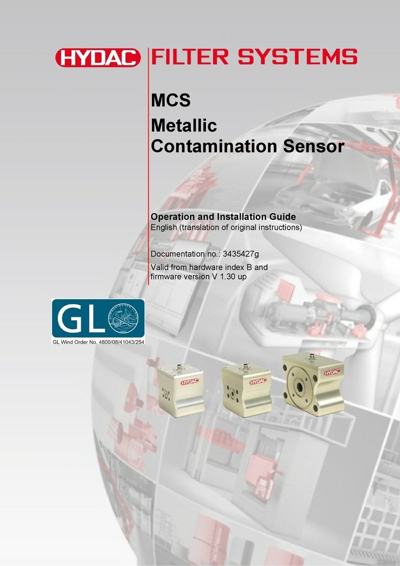
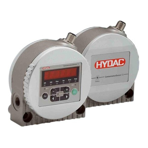
Hydac SMU 1200 User manual

SMU 1200
SensorMonitoring Unit
Operating Instruction
Valid from firmware versions V2.0 up
English (translation of original instructions)
Document No.: 3854281

Imprint
SensorMonitoring Unit - SMU en(us) Page 2 / 100
BeWa SMU1200 3854281 V2.0x en(us) 2013-08-20 2013-08-20
Imprint
Publisher and responsible for the content:
HYDAC FILTER SYSTEMS GMBH
Postfach 1251
66273 Sulzbach / Saarland
Germany
Telephone: +49 (0)6897 509 01
Telefax: +49 (0)6897 509 846
Homepage: www.hydac.com
Court of Registration: Saarbrücken, HRB 17216
Executive Director: Mathias Dieter,
Dipl.Kfm. Wolfgang Haering
Documentation Representative
Mr. Günter Harge
c/o HYDAC International GmbH, Industriegebiet, 66280 Sulzbach / Saar
Telephone: ++49 (0)6897 509 1511
Telefax: ++49 (0)6897 509 1394
© HYDAC FILTER SYSTEMS GMBH
All rights reserved. No part of this work may be reproduced in any form (print,
photocopy or by other means) or processed, duplicated or distributed using
electronic systems without the written consent of the publisher.
These documents have been created and inspected with the greatest care.
However, errors cannot be ruled out completely.
All details are subject to technical modifications. Technical specifications are
subject to change without notice.
The trademarks of other companies are exclusively used for the products of
those companies.

Content
SensorMonitoring Unit - SMU en(us) Page 3 / 100
BeWa SMU1200 3854281 V2.0x en(us) 2013-08-20 2013-08-20
Content
Imprint............................................................................................................2
Documentation Representative ...................................................................2
Content ..........................................................................................................3
Preface...........................................................................................................7
Technical Support........................................................................................8
Modifications to the Product ........................................................................8
Warranty ......................................................................................................8
Using the documentation .............................................................................9
Safety information ......................................................................................10
Hazard symbols.........................................................................................10
Signal words and their meaning in the safety information and
instructions ................................................................................................11
Structure of the safety information and instructions...................................11
Observe regulatory information .................................................................12
Proper/Designated Use .............................................................................12
Improper Use or Use Deviating from Intended Use ...................................14
Qualifications of personnel / target group ..................................................15
Storing the SMU ..........................................................................................16
Storage conditions.....................................................................................16
Transporting the SMU ................................................................................17
Decoding the type label..............................................................................18
Checking the scope of delivery .................................................................19
SMU Features ..............................................................................................20
Dimensions..................................................................................................21
Fastening / Mounting the SMU...................................................................22
Fastening the SMU temporarily to magnetizable surfaces.........................23
Permanent fastening of the SMU on the top hat rail ..................................24
Connecting the SMU...................................................................................25
SMU interface overview.............................................................................25
Sensor interface A - CS1000 IN / MCS1000 IN .........................................27
Sensor Interface B - AS1000 IN ................................................................27
Interface C - CS1000 OUT / MCS1000 OUT .............................................27
8-pin connection cable, open cable end: ................................................28
Interface D - AS1000 OUT.........................................................................29
5-pin connection cable, open cable end: ................................................29
Interface E - voltage supply .......................................................................30
Interface F - USB.......................................................................................30

Content
SensorMonitoring Unit - SMU en(us) Page 4 / 100
BeWa SMU1200 3854281 V2.0x en(us) 2013-08-20 2013-08-20
Interface G.................................................................................................31
HSI (Hydac Sensor Interface) – SMU 126x … .......................................31
ETH (Ethernet) – SMU 127x … ..............................................................31
Connecting the sensors .............................................................................32
Examples of connection.............................................................................34
SMU126x <-> CS1000 / AS1000...............................................................34
SMU12x1 <-> Bluetooth ............................................................................35
SMU127x <-> CS1000 / AS1000 -> LAN...................................................36
Operating the SMU......................................................................................37
Display (CS1000 and AS1000)..................................................................37
Display (MCS1000 and AS1000)...............................................................38
Internal measurement data memory..........................................................39
Keyboard elements....................................................................................40
Activating/deactivating key lock .................................................................40
Switching the display on and off ................................................................41
Scrolling through the displays ..................................................................42
CS1000 displays........................................................................................42
Display ISO.SAE ....................................................................................42
Display ISO.NAS ....................................................................................43
Measured variables CS1000 .....................................................................44
Measured variable "ISO" ........................................................................44
Measured variable "SAE" .......................................................................44
Measured variable "NAS" .......................................................................44
Service variables (only for CS1000) ..........................................................45
Service variable "Flow"...........................................................................45
Service category "Out" ...........................................................................45
Service variable "Drive"..........................................................................45
Service category "Temp"........................................................................45
MCS1000 displays.....................................................................................46
Measured variables MCS1000 ..................................................................47
Measured variable "SUM" ......................................................................47
Measured variable "CYCLE" ..................................................................47
Representation of numbers over 9999 ...................................................47
Service variables (only for MCS1000) .......................................................48
Service variable "Status" ........................................................................48
Service variable "Fi" ...............................................................................48
Service category "Temp"........................................................................48
AquaSensor AS1000 measured variables..............................................49
Measured variable "Water saturation" ....................................................49
Measured variable "Temperature"..........................................................49
Configuring the SMU ..................................................................................50
PowerUp Menu..........................................................................................51
Content
SensorMonitoring Unit - SMU en(us) Page 5 / 100
BeWa SMU1200 3854281 V2.0x en(us) 2013-08-20 2013-08-20
DAT.TIM – date / time ............................................................................52
ADRESS – Setting HSI bus address / TCP/IP address..........................53
REC.MOD – Set data recording .............................................................55
DEL.MEM – Delete Memory...................................................................56
SENS A – Sensor A PowerUp menu......................................................57
SENS B – Sensor B PowerUp menu......................................................59
SEN.ADR – Set sensor address.............................................................60
DFAULT – reset to factory settings ........................................................61
CANCEL.................................................................................................62
SAVE – store data..................................................................................62
Measuring Menu........................................................................................63
RECORD – Record measurements........................................................64
MEMORY – show free memory space ...................................................65
REC.TIM – Set recording interval...........................................................66
ED.MPNT – Change the name of measurement points .........................67
Setting OIL.CON – display screen for OilCondition sensors ..................69
TP.UNIT – change the temperature units °C / °F ...................................69
SENS A – Sensor A Measuring Menu....................................................70
SENS B – Sensor B Measuring Menu....................................................71
CANCEL.................................................................................................71
SAVE – save data ..................................................................................72
USB interface ..............................................................................................73
Copying measurements onto a USB data stick .........................................73
Data transmission failed - "ERROR COPY"...............................................76
Bluetooth interface .....................................................................................77
Installing the Bluetooth USB adaptor.........................................................78
Guarantee and liability for the USB adapter ...........................................78
Connecting the SMU via Bluetooth............................................................78
Evaluating stored records..........................................................................79
Directories to store the records..................................................................79
Record file names......................................................................................81
Evaluating the file containing the measurements ......................................82
The measurements are shown as dates ................................................84
Measurement value readouts with FluMoS...............................................85
Status messages / error messages ...........................................................86
Disposing of the SMU.................................................................................90
Customer service........................................................................................90
Model Code..................................................................................................91
Measurement sensors combination...........................................................91
Factory default settings .............................................................................92

Content
SensorMonitoring Unit - SMU en(us) Page 6 / 100
BeWa SMU1200 3854281 V2.0x en(us) 2013-08-20 2013-08-20
Accessories.................................................................................................93
Technical data.............................................................................................95
Overview - Compatible USB sticks............................................................96
EC declaration of conformity.....................................................................97
Index ............................................................................................................98

Preface
SensorMonitoring Unit - SMU en(us) Page 7 / 100
BeWa SMU1200 3854281 V2.0x en(us) 2013-08-20 2013-08-20
Preface
We have compiled the most important instructions for the operation and
maintenance of our product for you, its user, in this documentation.
It will acquaint you with the product and assist you in obtaining maximum
benefit in the applications for which it is designed.
You should keep it in the vicinity of the product so it is always at your
fingertips.
Note that the information on the unit's engineering contained in the
documentation was that available at the time of publication.Consequently,
there might be deviations in technical details, illustrations and dimensions.
If you discover errors while reading the documentation or have suggestions
or other useful information, please don’t hesitate to contact us:
HYDAC FILTER SYSTEMS GMBH
Technische Dokumentation
Postfach 12 51
66273 Sulzbach / Saar
Germany
We look forward to receiving your input.
“Putting experience into practice”

Preface
SensorMonitoring Unit - SMU en(us) Page 8 / 100
BeWa SMU1200 3854281 V2.0x en(us) 2013-08-20 2013-08-20
Technical Support
Contact our technical sales department if you have any questions regarding
our product. When contacting us, please always include the model/type
designation, serial no. and article no. of the product:
Fax: ++49 (0) 6897 / 509 - 846
Modifications to the Product
We would like to point out that changes to the product (e.g. additional
purchase of options, etc.) may result in the information in the operating
instructions no longer being completely accurate or sufficient.
After modification or repair work that affects the safety of the product has
been carried out on components, the product may not be returned to
operation until it has been checked and approved by a HYDAC technician.
Please notify us immediately of any modifications made to the product
whether by you or a third party.
Warranty
For the warranty provided by us, please refer to the General Terms of Sale
and Delivery of HYDAC Filter Systems GmbH.
You'll find this under www.hydac.com -> Legal information

Preface
SensorMonitoring Unit - SMU en(us) Page 9 / 100
BeWa SMU1200 3854281 V2.0x en(us) 2013-08-20 2013-08-20
Using the documentation
Note that the method described for locating specific information
does not release you from your responsibility of carefully reading
all these instructions prior to starting the unit up for the first time
and at regular intervals in the future.
WHAT do you want to know?
I determine which topic I am looking for.
WHERE can I find the information I’m looking for?
The document has a table of contents at the beginning. I select the chapter
I'm looking for there and the corresponding page number.
de
HYDACFiltertechnikGmbH
BeWa123456ade
Se ite x
Produkt/Kapitel
200x-xx-xx
The documentation number with its index enables you to order another copy
of the operating and maintenance instructions. The index is incremented
every time the manual is revised or changed.
Documentation no.
with index/
file name
Document language
Page number
Edition date
Chapter

Safety information
SensorMonitoring Unit - SMU en(us) Page 10 / 100
BeWa SMU1200 3854281 V2.0x en(us) 2013-08-20 2013-08-20
Safety information
The device was built according to the statutory provisions valid at the time of
delivery and satisfies current safety requirements.
Any residual hazards are indicated by safety information and instructions and
are described in the operating instructions.
Observe all safety and warning instructions attached to the unit. They must
always be complete and legible.
Do not operate the unit unless all the safety devices are present.
Secure the hazardous areas which may arise between the unit and other
equipment.
Maintain the unit inspection intervals prescribed by law.
Document the results in an inspection certificate and keep it until the next
inspection.
Hazard symbols
These symbols are listed for all safety information and instructions in these
operating instructions which indicate particular hazards to persons, property
or the environment.
Observe these instructions and act with particular caution in such cases.
Pass all safety information and instructions on to other users.
General hazard
Danger due to electrical voltage / current

Safety information
SensorMonitoring Unit - SMU en(us) Page 11 / 100
BeWa SMU1200 3854281 V2.0x en(us) 2013-08-20 2013-08-20
Signal words and their meaning in the safety information and
instructions
DANGER
DANGER indicates a hazard with a high risk and which will lead to death or
serious injury if not avoided.
WARNING
WARNING indicates a hazard with a medium risk and which can lead to
death or serious injury if not avoided.
CAUTION
CAUTION indicates a danger with a low risk and which can lead to minor
injury if not avoided.
NOTICE
NOTICE indicates a danger which will lead to damage to property if not
avoided.
Structure of the safety information and instructions
All warning instructions in this manual are highlighted with pictograms and
signal words. The pictogram and the signal word indicate the severity of the
danger.
Warning instructions listed before an activity are laid out as follows:
SIGNAL WORD
Type and source of danger
Consequence of the danger
HAZARD SYMBOL
►Measures to avert danger

Safety information
SensorMonitoring Unit - SMU en(us) Page 12 / 100
BeWa SMU1200 3854281 V2.0x en(us) 2013-08-20 2013-08-20
Observe regulatory information
Also observe the following regulatory information and guidelines:
Legal and local regulations for accident prevention
Legal and local regulations for environmental protection
Country-specific regulations, organization-specific regulations
Proper/Designated Use
WARNING
Strong magnets on the SMU
Life-threatening danger for persons with
cardiac pacemakers
►Maintain sufficient clearance between
yourself and the magnets
NOTICE
Connection of the SMU to board networks
The SMU1200 will be destroyed
►Use the SMU only on board networks which have a central
"Load Dump" fuse.
The Load Dump with a maximum of 30 V DC must be installed and
effective.
NOTICE
Exceeding the maximum permissible line length
Erroneous or no communication
►Observe the maximum permissible line lengths

Safety information
SensorMonitoring Unit - SMU en(us) Page 13 / 100
BeWa SMU1200 3854281 V2.0x en(us) 2013-08-20 2013-08-20
Only use the sensor for the application described in the following.
The SensorMonitoring Unit is for connecting two sensors for the continuous
monitoring of fluids in hydraulic and lubrication systems.
By displaying, storing and forwarding measurement data for particle
contamination in the ultra-fine or coarse particle range and for relative
saturation of the fluid with water, it is possible to perform condition-based
service and maintenance procedures.
Any other use shall be deemed to be improper and not in keeping with the
product's designated use. HYDAC accepts no liability for any damage
resulting from such use.
Proper or designated use of the product extends to the following:
Connection with the suitable sensors provided
Observing all the notes contained in these operating instructions

Safety information
SensorMonitoring Unit - SMU en(us) Page 14 / 100
BeWa SMU1200 3854281 V2.0x en(us) 2013-08-20 2013-08-20
Improper Use or Use Deviating from Intended Use
DANGER
Hazard due to use of the unit other than that
intended
Bodily injury and damage to property will result
when operated improperly.
►Never operate the sensor in potentially
explosive atmospheres.
►The sensor is only to be used with the
permitted media.
Any use extending beyond or deviating therefrom shall not be considered
intended use. HYDAC Filter Systems GmbH will assume no liability for any
damage resulting from such use. The user alone, shall assume any and all
associated risk
Improper use may result in hazards and/or will damage the sensor. Examples
of improper use:
Operation in potentially explosive atmospheres.
Operation with a non-approved sensor.
Operation under non-approved operational conditions.
Modifications to the sensor made by the user or purchaser.
Improper connection of the voltage and sensor cables.
Operation on board networks without central "Load Dump" fuse.

Safety information
SensorMonitoring Unit - SMU en(us) Page 15 / 100
BeWa SMU1200 3854281 V2.0x en(us) 2013-08-20 2013-08-20
Qualifications of personnel / target group
Persons who work on the sensor must be aware of the associated hazards
when using it.
Auxiliary and specialist personnel must have read and understood the
operating instructions, in particular the safety information and instructions,
and applicable regulations before beginning work.
The operating instructions and applicable regulations are to kept so they are
accessible for operating and specialist personnel.
These operating instructions are intended for:
Auxiliary personnel: such persons have been instructed about the sensor and
are aware of potential hazards due to improper use.
Specialist personnel: such persons with corresponding specialist training and
several years work experience. They are able to assess and perform the
work assigned to them, they are also able to recognize potential hazards.
Activity Person Knowledge
Transport / storage Auxiliary
personnel
No specialist knowledge
required
Electric installation,
first commissioning,
troubleshooting,
Shutdown
Specialist
personnel
Safe handling/use of tools
Fitting and connection of
electrical lines
Knowledge of network
communication
Knowledge of using Windows
PCs and of program
installation
Product-specific knowledge
Operation, operations
control
Specialist
personnel
Knowledge of using Windows
PCs
Product-specific knowledge
Dismantling, disposal Specialist
personnel
Proper and environmentally-
friendly disposal of materials
and substances
Knowledge about reuse

Storing the SMU
SensorMonitoring Unit - SMU en(us) Page 16 / 100
BeWa SMU1200 3854281 V2.0x en(us) 2013-08-20 2013-08-20
Storing the SMU
Make sure to store the SMU in a clean, dry place, in the original packing, if
possible. Do not remove the packing until you are ready to install the unit.
Storage conditions
Storage temperature: -40 °C … 80 °C / -40 °F … + 176 °F
Relative humidity: maximum 95%, non-condensing

Transporting the SMU
SensorMonitoring Unit - SMU en(us) Page 17 / 100
BeWa SMU1200 3854281 V2.0x en(us) 2013-08-20 2013-08-20
Transporting the SMU
WARNING
Strong magnetic field around the magnets
Life-threatening danger for persons with
cardiac pacemakers
►Maintain sufficient clearance between
yourself and the magnets
NOTICE
Strong magnetic field around the magnets
Magnetic strips and magnetizable objects can be damaged.
►Maintain sufficient clearance from magnetic strips on credit cards,
watches, jewelry, etc.
Transport the SMU by hand. During transport, avoid any localized pressure
points, especially on the displays.

Decoding the type label
SensorMonitoring Unit - SMU en(us) Page 18 / 100
BeWa SMU1200 3854281 V2.0x en(us) 2013-08-20 2013-08-20
Decoding the type label
For identification details of the SMU, see the type label. This is located on the
back of the unit and contains the exact product description and the serial
number.
Row -> Description
Model -> Model code; for details, see page 91
P/N -> Part no.
S/N -> Serial no.
Date -> Year/week of production and hardware index
Supply Voltage: -> Supply voltage range

Checking the scope of delivery
SensorMonitoring Unit - SMU en(us) Page 19 / 100
BeWa SMU1200 3854281 V2.0x en(us) 2013-08-20 2013-08-20
Checking the scope of delivery
The SMU comes packed and factory-assembled. Before commissioning the
SMU, check the content of the package to make sure everything is present.
The following items are supplied:
Item Qty. Designation
1 1 SensorMonitoring Unit SMU
2 1 USB Memory stick
3 1 Connection cable, 5-pin with
open cable end, L = 5 m
ZBE 47S-05
4 1 Connection cable, 5-pin,
plug/socket, L = 5 m
ZBE 30-05
5 1 Connection cable, 8-pin,
plug/socket, L = 5 m
ZBE 43-05
- 1 Top hat rail (35 mm), L= 200 mm
- 1 Operating Instructions (this
document)
- 1 CD - FluMoS light
ZBE 47S-05
ZBE 43-05
ZBE 30-05
54 3
2
1

SMU Features
SensorMonitoring Unit - SMU en(us) Page 20 / 100
BeWa SMU1200 3854281 V2.0x en(us) 2013-08-20 2013-08-20
SMU Features
The SensorMonitoring Unit SMU is used for the presentation and memory
storage of the measured values of Fluid Sensors.
The following fluid sensors can be connected directly, depending on the SMU
model:
-ContaminationSensor CS1000 (sensor interface A)
-Metal ContaminationSensor MCS1000 (sensor interface A)
-AquaSensor AS1000 (Sensor interface B)
The measured values for the connected sensors are shown on the display.
The values can be read off via USB memory stick for further processing and
evaluation of data and thus simply transferred to Office applications, for
example FluMoS or MS-Excel.
Uses for the SMU include:
-Presentation and memory storage of the measured values of Fluid
Sensors
-Parameterization of Fluid Sensors
-Test installation for testing Fluid Sensors
-Permanent installation of Fluid Sensors
Advantages offered by the SMU unit:
-Cost-effective, easy-to-install solution
-Simple processing and evaluation with FluMoS or MS Excel
-USB interface for transferring data onto a USB memory stick
-HSI interface for connecting HMG3000 or CSI-F-10 or
Ethernet interface for simple integration into an existing network via IP
address
-Bluetooth interface for data transfer and/or for visualization, e.g. on a
smartphone / PC via FluMoS
-Representation and/or parameterization of sensors without their own
display (e.g. AS1000)
-Interface for routing the analog and/or switching outputs of connected
Fluid Sensors
Table of contents
Other Hydac Accessories manuals

Hydac
Hydac MCS1 T001 Series Quick start guide

Hydac
Hydac CS 1000 Series User manual

Hydac
Hydac MCS1510-5-0 Instruction Manual

Hydac
Hydac MCS 13 series Quick start guide

Hydac
Hydac CS 1x10-A-0-0-0-1/-000 Instruction manual

Hydac
Hydac MCS****-C062 series Quick start guide

Hydac
Hydac VibrationSensor VS 3000 Quick start guide

Hydac
Hydac CS 1x11-A-0-0-0-0/-000 Instruction manual

Hydac
Hydac ContaminationSensor CS1220 VIMS Manual

Hydac
Hydac CS 1000 Series Manual