manuals.online logo
Brands
  1. Home
  2. •
  3. Brands
  4. •
  5. Azbil
  6. •
  7. Accessories
  8. •
  9. Azbil HTY7843 User manual

Azbil HTY7843 User manual

E1
CP-SP-1152E
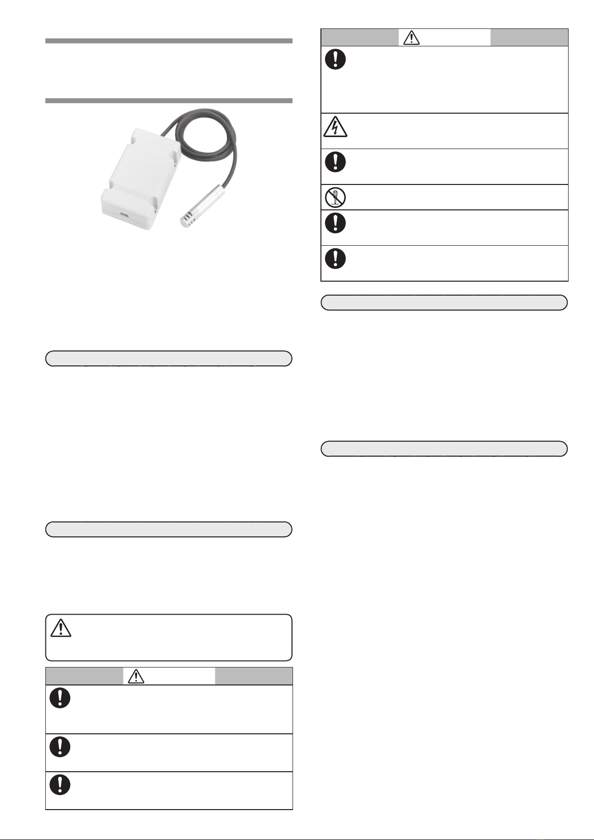
Temperature and Humidity Sensor with
Extensible Probe Model HTY7843
User’s Manual
Thank you for purchasing an Azbil Corporation product.
This manual contains information for ensuring the correct
use of this product. This manual should be read by those
who design and maintain equipment that uses this product.
Be sure to keep this manual nearby for handy reference.
Please read “Terms and Conditions”from the following URL
before ordering and use.
https://www.azbil.com/products/factory/order.html
NOTICE
Be sure that the user receives this manual before the product
is used.
Copying or duplicating this user’s manual in part or in whole is
forbidden. The information and specifications in this manual
are subject to change without notice.
Considerable effort has been made to ensure that this manual
is free from inaccuracies and omissions. If you should find an
error or omission, please contact the azbil Group.
In no event is Azbil Corporation liable to anyone for any
indirect, special or consequential damages as a result of using
this product.
SAFETY PRECAUTIONS
Safety precautions are for ensuring safe and correct use of
this product, and for preventing injury to the operator and
other people or damage to property. You must observe these
safety precautions. Also, be sure to read and understand the
contents of this user’s manual.
lKey to symbols
CAUTION
Cautions are indicated when mishandling this product
may result in minor injury or property damage only.
CAUTION
To ensure the safety, the connection work must be
carried out only by the authorized engineers having
special skill about instrumentation and electric con-
struction work.
Always operate the device within the rated input/out-
put specification range defined in this manual. Failure
to do so might cause faulty operation.
Always install the device in the operating environment
clarified in this manual. Failure to do so might cause
faulty operation.
CAUTION
Compositions of gas to be measured, such as corrosive
gas or organic solvent might cause measurement error,
short product service life, or faulty operation. When
operating the device in an environment other than
the normal air environment, always consult an Azbil
Corporation salesperson.
Before mounting, removing, or wiring this device, be
sure to turn off the power to this device and all con-
nected devices. There is a danger of electric shock.
Carry out the wiring work properly according to the
predetermined indoor wiring and electric equipment
technical standards.
Do not disassemble the device. Doing so might cause
faulty operation.
If the device malfunctions, excessively humid state may
occur due to output drop. When necessary, take appro-
priate safety measures on the system or equipment side.
When disposing of the device, dispose of it appropri-
ately as industrial waste in accordance with local bylaws
and regulations.
UNPACKING
When unpacking the HTY7843, check that the model No. you have
received is the product you ordered, that the product does not have
any apparent physical damage, and that all accessories are included.
If any damage is found or any package contents are missing, imme-
diately contact your dealer. The product package includes the follow-
ing accessories:
• Main body
• Tie-up band
• Sponge
• User’s Manual CP-UM-5304
OVERVIEW
Overview
This separate type temperature humidity sensor HTY7843 is a
highly precise and reliable sensor, in which a Pt100 platinum
RTD (JIS C1604 class A) is used for the temperature sensing ele-
ment and a polymer capacitive film humidity sensing element
(Azbil Corporation’s development model No. FP3™) is used for
the humidity detection element. This separate type temperature
humidity sensor provides a wide measuring range and excellent
stability.
Therefore, this sensor can be used for measurement of the outside
air and in various industrial fields, such as insides of air-condi-
tioner ducts and chambers.
Features
• The temperature and humidity can be measured precisely in a
wide range.
• The environment-proof is excellent.
• The long-term stability is excellent.
• The responsibility and reproducibility are excellent.
• The probe is separated from the amplifier to achieve a com-
pact design. This allows measurement in a narrow space and
mounting on a small device.
• As an optional filter is attached to the probe, the protection
structure of the probe is improved to the IP54 dust-proof and
splash-proof structure.
• This sensor is applicable to the CE marking.
Directives: 2004/108/EC (Electromagnetic Compatibility
(EMC) directive)
EN 50081-1/1992(EN 55011/1998 group1, class B)
EN61326-1/2006 (EN61000-4-2 to 4, 6)
E2
lWhen using the mounting bracket (Model No.: FL-PA112):
This bracket is used to mount the probe in parallel to the wall
surface.
lWhen using the seal connector:
This connector is used to mount the probe through the wall.
• Filter is not used.
Seal connector *
(Part No.: 83104098-003)
Probe
Seal connector
Sensor
Wall
• Filter is used.
Use of this filter makes it possible to improve the protec-
tion structure level to the IP54 dust-proof and splash-proof
structure.
Filter
* When mounting the filter, use the seal connector Part No.
83104098-004.
Mounting the amplifier
Mount the amplifier on a flat wall surface with four M3 screws.
To keep a sufficient maintenance and inspection space, do not
mount any device in the shaded portions.
Unit: mm
20 20
20
140
20
100
Amplifier
WIRING
CAUTION
Do not stretch any lead wire. Doing so might cause the
sensor to malfunction or faulty wiring.
For the crimp terminal, use the crimp terminal for the M3 screw ter-
minal (JST Mfg. Co. VD1.25-N3A or its equivalent). When using the
voltage output or temperature (3-wire RTD) output, the maximum
wiring length is 50 m.
After the wiring has been completed, make sure again that the wiring
is connected properly before turning ON the power.
MODEL SELECTION GUIDE
Select a model No. from Table below:
Basic
model
No.
Power Humidity
output
Temperature
output (Fixed) Description
HTY7843 Temperature and humidity
sensor with the FP3 sensor
element and extensible
probe
D24 V DC
1 Voltage output:
1–5 V / 0–100 %RH
4 Current output (2-wire
system): 4–20 mA /
0–100 %RH
1 Voltage output: 1–5 V /
0–50 °C
4 Current output (2-wire sys-
tem): 4–20 mA / 0–50 °C
A Voltage output: 1–5 V /
15–35 °C
P JIS Pt100 resistance output
(3-wire system)
00 —
• When the humidity is output by current, the temperature is output by current
or resistance.
• When the humidity is output by voltage, the temperature is output by voltage
or resistance.
MOUNTING
Mounting Locations
Mount this sensor in a place shown below where:
• The typical temperature and humidity of gas to be measured
can be detected and the specified wind velocity can be kept.
• The entire opening of the probe is put in gas to be measured
and the gas flow may be in contact with the probe in the hori-
zontal direction.
• No water drops directly splash onto the probe and no conden-
sation occurs.
• Sufficient maintenance and inspection space can be kept.
Handling Precautions
• If this sensor is mounted in a place where a large
amount of fine particle dust exists, attach the optional
filter to the sensor.
Mounting the probe
CAUTION
Do not stretch the cable between the probe and
amplifier. Doing so might cause cable disconnection
or faulty wiring.
Isolate the probe electrically from its surroundings.
When mounting this sensor on a steam heating air-
conditioner, take appropriate measures so that any
hot steam does not splash onto it. (If any hot steam
splashes onto the sensor, this might cause faulty
operation.)
Handling Precautions
• Do not mount the sensor with the opening of the probe
faced upward. Doing so might cause water drops to ac-
cumulate in the opening.
E3
Wiring diagram
lHumidity output is the voltage output
(Model No.: HTY7843D1_ _ _)
7 123456
NC
ABB
TEMP. HUMI. GND 24 V DC
Temperature output
(Voltage)
Temperature
output (3-wire RTD)
Humidity output
(Voltage)
24 V DC
power supply
Recommended cable: AWG22 or the equivalent
lHumidity output is the current output
(Model No.: HTY7843D4_ _ _)
Use a shielded multicore cable (outer diameter: 5 mm max.).
• Recommended cables
2-core: Taiyo Cabletec Corp.
Sunlight Series SX,
1 pair × 0.3 mm each
2-core: Hitachi Cable, Ltd.
UL2481 TR-64,
2 conductors × 24 AWG
3-core: Hitachi Cable, Ltd.
UL2482 TR-64,
3 conductors × 24 AWG
Temperature output
(4 to 20 mA)
Humidity output
(4 to 20 mA)
Temperature output
(3-wire RTD)
1 5432
H+ NC/A
H- T+/B T-/B
E
Transmitter
Power Supply
Transmitter
Power Supply
Note: The above shows a wiring example when both the
temperature and humidity are the current output.
Handling Precautions
• In the voltage output type sensor, the negative line of
the voltage output is short-circuited with the negative
line of the 24 V DC power supply. Therefore, great care
should be taken if other units also use the same power
supply commonly.
Wiring method
(1) Remove the cover of the
amplifier. As shown in the
Fig. right, remove the cover so
that it is raised with its long sides
kept pushed.
Cover
Push
(2) When the humidity output is the voltage output:
Attach crimp terminals to the
lead wires and connect them to
relevant terminals. (Terminal
tightening torque: 0.5 N·m)
Screw
terminal (M3)
for wiring
When the humidity output is the current output:
Strip the sheath approximately
9 to 10 mm from the top of
the lead wire and connect it to
relevant single touch terminal so
that the wiring label on the lead
wire is matched with that on the
terminal.
Handling Precautions
• Connect the shield to terminal E.
(3) Secure the cable to the case.
Humidity output is the
current output.
Humidity output is the
voltage output.
Wind the sponge
supplied with the sensor
around the cable, and
then secure the cable
with the tie-up band.
Sponge
Tie-up band
(4) Mount the cover to its original position.
Handling Precautions
• Do not operate the sensor with the cover removed. After
the wiring has been completed, always mount the cover
firmly again.
MAINTENANCE
This sensor has been inspected and adjusted properly before ship-
ment from the factory. Therefore, it is not necessary to make the
adjustment again at the installation site.
Carry out the maintenance of the sensor properly while referring to
the following items:
Periodic inspection
• According to the amount of fine particle dust flying in gas to be
measured or the contamination status, check the detection ac-
curacy periodically.
• Check the filter for clogging. When necessary, clean the filter.
If the filter is contaminated excessively, replace it with a new
one.
Troubleshooting
If any trouble is found during operation, inspect the sensor while
referring to the Table below and take corrective actions.
Trouble Inspection Corrective action
• Output
signal is not
output.
• Output
fluctuates.
• Check for loose wiring.
• Check the cable for
faulty wiring.
• Check the power
voltage.
• Check the sensor main
unit for breakage.
• Retighten the terminal.
• Carry out the wiring again.
• Replace the sensor.
• Output
response is
slow.
• Sensor main unit
gets damp or dew
condensation occurs.
• Remove the sensor from
the mounting place and dry
it naturally with the power
turned OFF in the clean
atmosphere.
• At this time, if the filter is
attached to the sensor,
detach it.
• Sensor has
a measuring
error.
• Check the mounting
location.
• Check the
contamination status of
the sensor main unit.
• Mount the sensor in a place
meeting the specified
conditions ( p.E2).
• Clean the filter.
• Replace the filter.
• Replace the sensor main
unit.
E4
1-12-2 Kawana, Fujisawa
Kanagawa 251-8522 Japan
URL: https://www.azbil.com
(11)
Specifications are subject to change without notice.
1st edition: July 2003 (M)
6th edition: Nov. 2019 (F)© 2003–2019 Azbil Corporation. All Rights Reserved.
SPECIFICATIONS
Item Specifications
Detection
accuracy
Temperature ±0.3 °C (Pt 100 output), ±0.5 °C (1 to 5 V DC output), ±0.5 °C (4 to 20 mA DC output)
Humidity ±3 %RH (30 to 70 %RH at 25 °C), ±5 %RH (20 to 80 %RH at 15 to 35 °C)
Output signal Temperature JIS Pt 100 (3-wire method)
1 to 5 V DC (The temperature range specified by model): the minimum input impedance is 50 kΩ.
4 to 20 mA DC (2-wire method): the maximum load resistance at a power voltage of 24 V DC is 500 Ω.
Humidity 1 to 5 V DC (Linear to 0 to 100 %RH): the minimum input impedance is 50 kΩ.
4 to 20 mA DC (2-wire method) (Linear to 0 to 100 %RH): the maximum load resistance at a power voltage of 24 V DC is 500 Ω.
Operating
environmental
conditions
Probe Rated operating conditions 0 to 50 °C 5 to 95 %RH (without condensation)
Limit operating conditions −20 to +80 °C 0 to 100 %RH (without condensation)
Transportation/Storage conditions −20 to +70 °C 5 to 95 %RH (without condensation)
Amplifier Rated operating conditions 0 to 50 °C 10 to 90 %RH (without condensation)
Limit operating conditions 0 to 50 °C 5 to 95 %RH (without condensation)
Transportation/Storage conditions −20 to +70 °C 5 to 95 %RH (without condensation)
Wind velocity 0 to 15 m/s
Time
constant*
Temperature 3 min or less
Humidity 30 s or less
Power voltage 24 V DC ± 10 %
Power consumption 0.2 W or less (When humidity output is the voltage output./HTY7843D1_00)
Dielectric strength Leak current is 1 mA or less when 500 V AC is applied for 1 min (Between case and power terminal)
Insulation resistance 20 MΩ or more when measured using 500 V DC-Megger (Between case and power terminal)
Vibration resistance 4.9 m/s
2
(10 to 65 Hz), 9.8 m/s
2
in the packing status (10 to 150 Hz for 2 h in each of X, Y, and Z directions)
Protection structure Probe: Dust-proof and splash-proof structure (IP54) (When the filter is attached.)
Mounting Amplifier: M3 screw × 4
Connection Voltage output type: Terminal base connection (M3 screw), Current output type: One-touch terminal
Material/Color Probe SUS304
Amplifier Modified PE resin, Gray (DIC-651 or its equivalent)
Mass Approximately 150 g (The mass of the probe is approximately 60 g.)
Accessories Tie-up band (1 unit), Sponge (1 unit)
* At wind velocity of 2 m/s
External dimensions Unit: mm
Cable length: 950 (±
50)
53
Φ12
100
60
29
60
60
Optional parts (Sold separately)
Name Part No.
Wall mounting bracket FL-PA112
Seal connector 83104098-003 (Without filter)
83104098-004 (With filter)
Filter 83162951-002

Other Azbil Accessories manuals

Azbil TY7043D User manual

Azbil

Azbil TY7043D User manual

Azbil SES70 User manual

Azbil

Azbil SES70 User manual

Azbil AUD100 Series User manual

Azbil

Azbil AUD100 Series User manual

Azbil CY8100C1001 User manual

Azbil

Azbil CY8100C1001 User manual

Azbil HTY 7033 User manual

Azbil

Azbil HTY 7033 User manual

Azbil HP7 Series User manual

Azbil

Azbil HP7 Series User manual

Azbil HTY78 User manual

Azbil

Azbil HTY78 User manual

Azbil K1G Series User manual

Azbil

Azbil K1G Series User manual

Azbil SES70 User manual

Azbil

Azbil SES70 User manual

Azbil K1G Series User manual

Azbil

Azbil K1G Series User manual

Azbil AUD100 Series User manual

Azbil

Azbil AUD100 Series User manual

Popular Accessories manuals by other brands

Nordic Home Culture LGT-001 user manual

Nordic Home Culture

Nordic Home Culture LGT-001 user manual

Atlantic Ultraviolet Sanidyne user manual

Atlantic Ultraviolet

Atlantic Ultraviolet Sanidyne user manual

Omnicomm LLS 5 user manual

Omnicomm

Omnicomm LLS 5 user manual

Choetech T315 user manual

Choetech

Choetech T315 user manual

Toyota 12V AUXILIARY POWER SOCKET owner's manual

Toyota

Toyota 12V AUXILIARY POWER SOCKET owner's manual

PCB Piezotronics 352C33 Installation and operating manual

PCB Piezotronics

PCB Piezotronics 352C33 Installation and operating manual

Bradcot Annexe Erection Instructions

Bradcot

Bradcot Annexe Erection Instructions

Scott Fetzer Carefree of Colorado Eclipse Universal installation manual

Scott Fetzer

Scott Fetzer Carefree of Colorado Eclipse Universal installation manual

PNY PowerPack 6600 user manual

PNY

PNY PowerPack 6600 user manual

Kenwood KN400 instructions

Kenwood

Kenwood KN400 instructions

weinor Plaza Viva Maintenance Instructions and Directions for use for the end user

weinor

weinor Plaza Viva Maintenance Instructions and Directions for use for the end user

Rain Bird WR2 user manual

Rain Bird

Rain Bird WR2 user manual

Anyload 805HP user manual

Anyload

Anyload 805HP user manual

IFM OY Series Original operating instructions

IFM

IFM OY Series Original operating instructions

Pop-A-Shot OUTDOOR I DUAL SHOT owner's manual

Pop-A-Shot

Pop-A-Shot OUTDOOR I DUAL SHOT owner's manual

La Crosse Technology CYCLONE PRO SENSOR quick start guide

La Crosse Technology

La Crosse Technology CYCLONE PRO SENSOR quick start guide

WD Plus BEARWARE 303492/20181211FS025 manual

WD Plus

WD Plus BEARWARE 303492/20181211FS025 manual

Axis T61 user manual

Axis

Axis T61 user manual

manuals.online logo
manuals.online logoBrands
  • About & Mission
  • Contact us
  • Privacy Policy
  • Terms and Conditions

Copyright 2025 Manuals.Online. All Rights Reserved.