MSA General Monitors TL105 User manual

The inf ormation and technical data disclosed in
this document may be used and disseminated
only for the purposes and to the extent
specifically authorized in writing by General
Monitors.
Instruction Manual 02-23
General Monitors reserves the right to change
published specifications and designs without
prior notice.
Part No. MANTL105
Revision
CR
M/02-23
800000058477
MODEL TL105
Test Lamp for Flame Detection

TL
105
ii
This page is intentionally left blank.

TL
105
iii
NOTE THIS IS YELLOW PAPER
WARNING: Do NOT leave battery uncharged. It will result in permanent
battery damage.

TL
105
iv
Page intentionally left blank

TL
105
v
Table of Contents
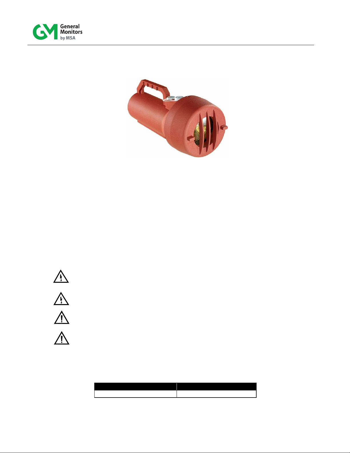
MODEL TL105 .........................................................................................................................I
TEST LAMP FOR FLAME DETECTION...................................................................................I
ABOUT THIS MANUAL........................................................................................................VIII
Format Conventions............................................................................................................viii
Notes, Cautions, and Warnings .................................................................................viii
Contacting Customer Support ...................................................................................viii
1.0 INTRODUCTION................................................................................................................9
1.1 Notice...................................................................................................................... 9
1.2 Sp ec ial Warnings ...................................................................................................... 9
1.3 D esc rip t io n............................................................................................................. 10
1.4 Upo n Rec ei vi ng....................................................................................................... 10
1.5 Tes t Lamp Operating Principle .................................................................................. 11
2.0 QUICK START GUIDE.....................................................................................................12
3.0 TEST LAMP COMPONENTS...........................................................................................13
3.1 Lamp Housing A ss emb ly .......................................................................................... 13
3.2 Microcontroller........................................................................................................ 13
3.3 Rotary Switch Setting............................................................................................... 13
3.4 Rechargeabl e B at tery .............................................................................................. 13
3.5 Power Jack ............................................................................................................ 13
3.6 Push Button............................................................................................................ 13
3.7 Aluminum Cas e and Cap .......................................................................................... 14
3.8 Battery Charge State Indicator................................................................................... 14
4.0 USE AND OPERATION...................................................................................................15
5.0 TEST LAMP MAINTENANCE AND WARRANTY.............................................................18
5.1 Maintenance........................................................................................................... 18
5.2 Cleaning the S app hi re Windo w.................................................................................. 18
5.3 Recharging the Battery............................................................................................. 19
5.4 Obtaining Service.................................................................................................... 19
5.5 Warranty................................................................................................................ 19
6.0 TROUBLESHOOTING GUIDE.........................................................................................21
CUSTOMER SUPPORT...................................................................................................22
7.0 22
7.1 Other Sources for Help............................................................................................. 22
8.0 APPENDIX ......................................................................................................................23

TL
105
vi
8.1 Sp ecif ic atio ns ......................................................................................................... 23
8.2 Regulatory Agency Approvals ................................................................................... 23
8.2.1 Reg ulato ry Ag enc ies..................................................................................... 23
8.2.2 Classification Area and Protection Methods...................................................... 24

TL
105
vii
Table of Figures
Figure 1: TL105 Test Lamp.................................................................................................................. 9
Figure 2: TL105 Battery Connection.....................................................................................................11
Figure 3: Approximate Distance between TL105 and a Flame Detector......................................................12
Fig ure 4: Ref l ec to r Mounting in Body....................................................................................................15
Figure 5: Location of Functional Board under Lamp Assembly..................................................................16
Table of Tables
Tab le 1: Ch arg e S t at e Indicator...........................................................................................................14
Table 2: Detector Test Mode Initiation or/Detector Alarm Trigger with TL105 ..............................................17
Tab le 3: Tro ub les hooting Table...........................................................................................................21
Tab l e 4: Loc atio ns .............................................................................................................................22

TL
105
viii
About This Manual
This manual provides instructions for operating, and maintaining the General Monitors (GM)
TL105 test lamp. The intended audience includes installation personnel, f ield service
technicians, and other technical staff involved in using a TL105.
Format Conventions
Several f ormat conventions are used throughout this manual for Notes, Cautions, and
Warnings. These conventions are described below.
Notes, Cautions, and Warnings
NOTE: Notes provide supplementary details such as exception conditions, alternate methods
for a task, time saving tips, and references to related information.
CAUTION: These notices describe precautions to prevent hazardous conditions t hat may
damage the equipment.
WARNING: These notices describe precautions to prevent hazardous conditions that m ay
cause injury to people working with the equipment.
Contacting Customer Support
For additional product inf ormation not contained in this manual, please contact General
Monitors Customer Support. Refer to Section 7.0 for contact information.

TL
105
9
1.0 Introduction
Figure 1: TL105 Test Lamp
1.1 Notice
All inf ormation contained in this instruction manual applies only to the setup and operation of
the TL105 test lamp with flame detectors provided by General Monitors. The s al e of t he t est
lamp does not license the user to reproduce GM drawings or to utilize any inf ormation
contained in this manual without prior written permission.
The TL105 test lamp is easy to set up and operate. However, this manual should be read in full,
and the inf ormation contained herein understood, before attempting to operate the test lamp i n
service.
1.2 Special Warnings
WARNING: Do NOT leave battery uncharged. It will result in permanent battery
damage.
WARNING: UV light is injurious to one’s vision. Do not stare into functioning lamp. Wear ey e
protection of UV blocking glasses to prevent eye injury.
CAUTION: Do not attempt to recharge the TL105 in areas where combustible gases or
potential explosive gases are located.
CAUTION: The f lamepaths are not intended to be repaired.
Special Condition of Use:
The flameproof joint is other than the minimum or maximumvalues detailedin EN/IEC 60079-1, the
value being as follows:
Location/Type
Length, L (mm)
Window/Flange
15.9

TL
105
10
1.3 Description
The TL105 is a battery operated rechargeable test lamp specifically designed to tes t General
Monitors’ UV, UV/IR, Digital Frequency IR, and Multi-Spectral IR flame detectors. The tes t lamp
provides a high-energy, broadband radiation source that emits suffic ient energy in b ot h t he
ultraviolet and infrared spectra to activate UV and/or IR detectors. To simulate the flickeri ng of
a f ire, the test lamp automatically flashes at various selectable rates.
1.4 Upon Receiving
TL105 Lamp leaves the factory with the battery disconnected. The customer must connect and
fully charge the battery before use.If you connect the battery and activate the push button, the
RED LED will stay on for 60 seconds. It will continue to do so until the battery has been fully
charged.
Since the TL105 goes to fault mode when a charger is plugging in and no battery is present,
you must plug in the battery before the charger.
Make sure the lens and the reflector are kept clean from debris and fingerprints. Grease on the
window will absorb and prevent the required energy from reaching the flame detector.
Please f ollow the steps outlined below to connect the battery:
•Loosen the Set Screw on the Cap.
•Unscrew the Cap counterclockwise and remove it from the Body.
•Remove the two screws holding Reflector on the Body.
•Pull the Ref lector off to reveal a 4-Pin Connector on the PC Board.
•Plug the 4 wire Connector coming from the Body into the 4 -Pin Connector on the PC
board . The pins on the connector align one way only.
•Reposition the Reflector on the Body and tighten 2 screws to hold the Reflector on the
Body.
•Reinstall the Cap to the TL105 Body by screwing it on clockwise.
•Tighten the Set Screw on the Cap.
•Follow Section 5.3 in the TL105 Instruction Manual to recharge the battery.
NOTE: If replacing the battery, it is first required to remove the retainer plate prior to removal of
the battery. Ensure the battery retainer plate is reinstalled prior t o reas semb ling the
unit.

TL
105
11
Figure 2: TL105 Battery Connection
1.5 Test Lamp Operating Principle
A variety of flashing test patterns, selectable through a rotary switch, allows t he t est lamp t o
check the operation of General Monitors flame detectors. When the specific flashing pattern for
a given type of flame detector is appropriately selected, the test lamp triggers the alarm or t est
mode. Please refer to Table 2 for rotary switch settings.

TL
105
12
2.0 Quick Start Guide
Figure 3: Approximate Distance between TL105 and a Flame Detector
It is important to begin a series of flame detector checks with a fully charged TL105.
•Stand between 10 and 35 feet from a Flame Detector that is to be tested and aim the
TL105 directly into the detector window.
•Aim the TL105 at the detector f ace then press the ON button and be sure the high
intensity pulsing beam strikes the detector face squarely.
•On some Flame Detectors shaking the lamp quickly from side to side or up and down
in a manner that creates an intermittent illumination of the detector may increase the
simulation of flame flicker and improve the response of the flame detector to the lamp.
•When the Flame Detector senses the Test Lamp, the red LED will blink slowly. The
green light may also blink. After a time delay the red LED will st art to b link qui ckly.
This signifies the completion of the test.
NOTE: Please ref er to Table 2 for maximum distance to each detector.
NOTE:The TL105 triggers a Flame Det ec tor into alarm. The system must be disabled during
test if you do not want false trips.
To conserve charge, do not operate the test lamp longer than is necessary to test a Flame
Detector.
When the battery level drops below the level required to maintain the proper intensity of the
lamp, an internal low voltage circuit will shut the lamp off until the battery has been recharged.
Please ref er to Section 5.3 for complete recharging instructions.
It is mandatory that the TL105 be kept on charge when not in use to prevent excessive battery
discharge. The batteries may be charged an average of 500 times before the batt ery p ack is
replaced.
NOTE:Please ref er to Section 3.8 for Battery Charge State Indicator details.
NOTE: Please ref er to Section 5.3 for detailed information on Recharging the Battery. The
normal recharge time for the rechargeable battery is 3.5 hours.
10-35 f t

TL
105
13
3.0 Test Lamp Components
3.1 Lamp Housing Assembly
NOTE: Do not put fingerprints on the reflector or the light bulb, as this will reduce the available
radiation required by the individual detector.
The lamp housing assembly consists of a gold-plated parabolic reflector with the lamp affixed to
its center. A light emitting diode (LED) that serves as a battery charge indicator is also housed
near the edge of the reflector.
3.2 Microcontroller
The TL105’s f lashing patterns are controlled by a microcontroller. This device also monitors
battery voltage and shuts down the flash lamp output when the battery charge is low. The
microcontroller resides on the functional board.
3.3 Rotary Switch Setting
A rotary switch is used to configure the test lamp to function with FL3XXX, FL4000, FL4000H,
and Ty p e V UV and Type VI UV/IR d etectors. Positions of the rotary switch for eac h of t hese
detectors are noted in Table 2 and are labeled next to the rotary switch ins ide t he lam p. The
rotary switch resides on the functional board. (Do not operat e t he TL105 in f actory mode.
Damage may result to the TL105)
3.4 Rechargeable Battery
The TL105 test lamp is powered by a 12V rechargeable battery. It is mandatory to keep the test
lamp docked with its battery charger when the test lamp is not being used. This wi ll increase
the expected life of the battery and will always keep the test lamp available for immediate use.
WARNING: Do not leave battery uncharged. It will result in permanent battery damage.
NOTE: The normal recharge time for the rechargeable battery is 3.5 hours.
3.5 Power Jack
The power jack is located directly under the aluminum cap and can be accessed when the c ap
is removed. The cap must always be in place when operated in a hazardous location. An Allen
wrench is included with the test lamp to unscrew or affix the plug. With the plug removed, the
battery can be recharged by connecting the jack to the TL105 bat tery c harger. The b at tery
charger operates from a 110 – 240 VAC power line.
3.6 Push Button
The push button toggles the lamp ON or OFF. Press the button once to turn the lamp on, and
press it again to turn the instrument off. After f lashing for a maximum of 5 minut es, t he t est

TL
105
14
lamp will turn itself off. This is to prevent the battery becoming compl etel y di sc harged if t he
ON / OFF button is accidentally bumped on.
3.7 Aluminum Case and Cap
The TL105 red aluminum housing is explosion proof for use in hazardous locations (8.2.2). It
can also be used for general-purpose, non-hazardous applications.
3.8 Battery Charge State Indicator
The tri-color LED affixed to the gold parabolic reflector displays the charge state of the battery.
The f lashing patterns and colors of the signals are shown in Table 1.
Battery Charge
LED Color and Flashing Pattern
Fully charged
Solid green
Charging
Solid yellow
Charging paused
Blinking yellow. This occurs if the battery is too hot (> 60°C)
Fault
Blink red once per second
Discharged
Solid red for one minute after the push button is pressed, then off
Never charged &
switch pushed
Solid red for one minute after the push button is pressed, then off
Battery not connected
Solid red for one minute after the push button is pressed, then off
Wrong charger
connected
Solid red for one minute after the push button is pressed, then off
Table 1: Charge State Indicator
NOTE: The TL105 attempts to detect improper chargers. However it can not detect all improper
chargers, care must be used to ensure the proper charger is used.
If the improper charger is used, disconnect the charger and wait 1 minute until the red LED goes
out before connecting the proper charger.

TL
105
15
4.0 Use and Operation
Figure 4: Reflector Mounting in Body
Prior to opening of the test lamp make sure that the set screw located on thecap is loosened
suf ficiently to remove the cap.
When closing, make sure that the captive screws (located on the reflector) are mat ched with
the holes located on the body of the test lamp.
Bef ore beginning a flame detector check, adjust the rotary switch setting in the TL105 test lamp
according to the type of GM f lame detector used. Table 2 shows the rotary switch
conf igurations for GM flame detectors FL4000H, FL4000, FL3XXX, and Types V and VI. Usi ng
a f ully charged TL105, stand up to the distance specified in Table 2 from the flame detect or t o
be tested and aim the TL105 directly into the detector window. Press the ON button and ensure
the high intensity intermittent beam strikes the detector f ace. If the system is operating
normally, the instrument will go into a warning condition after a few flashes of the test l amp. If
the lamp remains on for the period set by the time delay adjustment, the Flame Detector will go
into alarm 1.
1For test initiation with the FL4000/FL4000H flame detecto r, please refer to the FL4000/FL4000H Instruction
Manual.

TL
105
16
NOTE: Bef ore testing any GM flame detector, see Table 2 and Figure 5 to ensure the rotary
switch setting is correct for the particular detector.
CAUTION:When operating in conditions involving fog, rain or frost, UV and IR radiation are
(diminished) with increasing levels of moisture. The moisture level will affect the potential range
of the detector. When using the test lamp in conditions of frost, make sure that the lens is f ree
of frost and ice. A plastic card can be used without scratching t he lens cap to remove frost
build-up.
NOTE:Recharging the battery and normal docking of the test lamp when not in use is
mandatory. This will extend the useful life of the battery and also make the t est lam p
available f or immediate use. Normal recharge time is approximately 3 hours; the
maximum recharge time is 3.5 hours.
Figure 5: Location of Functional Board under Lamp Assembly
NOTE: Location of the rotary switch in the TL105 control board, shown in Figure 5.
Rotary Switch
shown in
position 1 (f or
testing FL3100
Flame
Detectors)

TL
105
17
Detector Test Mode Initiation or Detector Alarm Trigger with TL105
Flame Detector
to Test
Rotary Switch Setting
Maximum Distance to
Detector (ft)
Results
UV & UV/IR Type
V & VI 15 UV & UV/IR Type V & VI
triggers into alarm mode
FL3000 15 FL3000 triggers into alarm
mode
FL3001 35 FL3001 triggers into alarm
mode
FL3002 10 FL3002 triggers into alarm
mode
FL3100/FL3100H 20 FL3100/FL3100H triggers into
alarm mode
FL3100-H2/
FL3100H-H240 FL3100-H2/FL3100H-H2
triggers into alarm mode
FL3101/FL3101H 35 FL3101/FL3101H triggers into
alarm mode
FL3102 10 FL3102 triggers into alarm
mode
FL3110 20 FL3110 triggers into alarm
mode
FL3111 35 FL3111 triggers into alarm
mode
FL3112 8 FL3112 triggers into alarm
mode
FL4000/FL4000H
FL500
35 (High Sensitivity)
20
FL4000/FL4000H enters test
mode
FL500 triggers into alarm
mode
FL4000/FL4000H
FL500
18 (Medium Sensitivity)
15
FL4000/FL4000H enters test
mode
FL500 triggers into alarm
mode
FL4000/FL4000H
FL500
8 (Low Sensitivity)
10
FL4000/FL4000H enters test
mode
FL500 triggers into alarm
mode
Table 2: Detector Test Mode Initiation or/Detector Alarm Trigger with TL105

TL
105
18
5.0 Test Lamp Maintenance and Warranty
5.1 Maintenance
Routine maintenance for the test lamp is minimal:
•When the test lamp is not being used, it is mandatory to ensure that the test l am p
is docked on the charger and the charger is connected to a l ive 110 – 240VAC
power supply adapter. Permanent battery damage will occur if not charged for 60
days.
•Make sure that the test lamp lens is free of frost or large accumulations of moisture
during f rosty conditions or inclement weather.
•The battery life will be affected by extreme temperatures. Store and charge the
battery between +5°C and +30°C (+41°F and 86°F) if possible.
There are no user serviceable parts inside the test lamp besides the battery pack. After a
number of years, the battery may fail. This will be indicated by a flashing red i ndi c at or at the
f ront of the lamp. The unit should be returned to General Monitors for a replacement battery or
a replacement battery pack may be ordered from General Monitors. See section 1.4 for battery
replacement instructions. If the test lamp is to be d is carded, the battery must be recycled at this
point.
In most countries it is illegal to dispose of the battery with other garbage. General Monitors has
a Recycle Program in place to recycle the used batteries.
NOTE: The removal of particulate matter and any filmbuildup on the Sapphire Window is
necessary to ensure proper sensitivity of the system. It is recommended that the
window be cleaned at least every 30 days if the detector is located in a particularly dirty
environment.
5.2 Cleaning the Sapphire Window
A clean, soft, lint-free cloth, tissue or cotton swab should be used to apply the cleaning solution.
The window is not glass; it is made from sapphire. The cleaning solution s hould b e General
Monitors P/N 10272-1 (Industrial Strength Windex®with Ammonia D).
Do not touch the window with fingers.
1. Wet the window with the solution.
2. Rub with a dry, unsoiled cloth until the window is clean.
3. Completely dry the window.
CAUTION: Do not use a commercial glass cleaner other than Industrial Strength Windex®with
Ammonia D.

TL
105
19
5.3 Recharging the Battery
Bef ore the lamp is used for the first time, or after it has been used to the point where the red
LED at the f ront has come on solidly, the battery must be recharged. To recharge the bat tery,
take the test lamp to a non-hazardous area where there is no possibility of an explosive gas or
dust atmosphere being present. The temperature in this area must be between 32°F (0°C) and
104°F (40°C). No damage will occur if the unit is outside the temperature range, but the battery
will not charge.
Use an Allen wrench to remove the charging plug stopper and connect the General Monitors
Switching Power Supply P/N 71676 to the charging socket exposed by removing the chargi ng
stopper.
Plug the Switching Power Supply into an electrical o utlet between 100 and 240 VAC 50 to 60
Hz rated to provide at least 1.5 A. The charge indicator LED at the front of the test lamp will
change to the color yellow to show that the battery lamp is charging. When the charge is
complete (less than 3.5 hours), the charge indicator will change to green. If the lamp is to be
stored, leave it connected to the Switching Power Supply to keep the battery charged.
Bef ore using the test lamp, unplug the charging connector from the test lamp, caref ull y insert
the charging plug stopper using an Allen wrench and screw it all the way into the hole. Do not
over-tighten the stopping plug. The lamp can now be safely used in hazard ous l ocat ions as
specified on the test lamp nameplate and in Section 8.2.2 of this manual.
5.4 Obtaining Service
The TL105 test lamp contains no user serviceable parts besides the battery pac k. To obtain
inf ormation regarding f actory service, contact General Monitors or your General Monitors
representative. Please have the following information available:
•Instrument model number (on the nameplate)
•Instrument serial number (on the nameplate)
•Description of the problem
5.5 Warranty
CAUTION:There are no user serviceable parts inside the Model TL105 test lamp. Work
perf ormed by persons not authorized by General Monitors will void the warranty.
General Monitors warrants the TL105 test lamp and the accessory battery charg er to be f ree
f rom defects in workmanship or material under normal use and servi ce wit hin two (2) years
f rom the date of shipment.
General Monitors will repair or replace without charge any equipment f ound t o b e d ef ective
during the warranty period. Full determination of the nature of, and responsibility for, defective
or damaged equipment will be made by General Monitors’ personnel.
Def ective or damaged equipment must be shipped prepaid to General Monitors or the
representative from which shipment was made. In all cases, this warranty is limited to the c ost

TL
105
20
of the equipment supplied by General Monitors. The customer will assume all li ability for the
misuse of this equipment by its employees or other personnel.
All warranties are contingent upon proper use in the application for whi c h t he produc t was
intended and do not cover products which have been modified or repaired without General
Monitors’ approval or which have been subjected to neglect, accident, improper installation or
application, or on which the original identification marks have been removed or altered.
Except for the express warranty stated above, General Monitors disclaims allwarranties with
regard to the products sold, including all implied warranties of merchantability and fi tness and
the express warranties stated herein are in lieu of all obligations o r li abi li t ies on t he part of
General Monitors for damages including, but not limited to, consequential damages arising out
of / or in connection with the use or performance of the product.
Other manuals for General Monitors TL105
1
Table of contents
Other MSA Test Equipment manuals

MSA
MSA SafEye Xenon 800 Series User manual

MSA
MSA galaxy GX2 User manual

MSA
MSA 697444 User manual

MSA
MSA Airetool GT Series Instruction and safety manual

MSA
MSA General Monitors SB100 User manual

MSA
MSA FlameGard 5 Test Lamp User manual

MSA
MSA Altair QuickCheck Station User manual

MSA
MSA Altair QuickCheck Station User manual

MSA
MSA galaxy GX2 User manual

MSA
MSA Multitest plus Console User manual