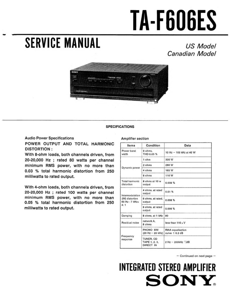
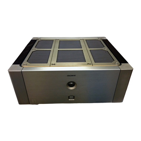
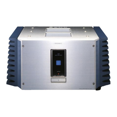
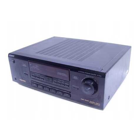
Sony TA-2000F User manual


-TA-2000F
Section
Title
Page
SERVICING
NOTES
...0000.......c:cccsssseteeecsseeeseeeeeres
]
1.
TECHNICAL
DESCRIPTION
1-1.
Technical
Specifications
............c..6.
2.
1-2.
Detailed
Circuit
Analysis
.............
3~8
1-3.
Block
Diagram
................ceceeseeeeeeeeeeees
9
1-4.
Level
Diagram
.............cccccceeeeseeeee
sees
10
2.
DISASSEMBLY
AND
REPLACEMENT
PROCEDURES
2-1.
Tools
Required
............
cess
eceeeseoee
eee
11
2-2.
Hardware
Identification
Guide
.......
11
2-3.
Top
Cover
and
Front
Panel
Removal
.......ccccccseceeeesseseceseeeeeeees
11
2-4.
Front
Subchassis
Removal
..............
12
2-5.
Level
Meter
and
Meter
Lamp
Replacement
.........
eee
eeeceeee
eee
eee
12
2-6.
PC
Board
Removal
...............00
12~13
2-7.
Rear
Panel
Removal
............ccceeeeees
13
2-8.
Control!
and
Switch
Replacement
.............ccseeeeeeee
13~14
2-9.
Replacement
of
Components
Secured
to
the
Rear
Panel
by
Rivets
oo...
eee
eeeceeeseeeeeees
14
2-10.
Chassis
Layout
0.0.0...
seeceeeeeeeee
15
3.
ALIGNMENT
AND
ADJUSTMENT
PROCEDURES
3-1.
Test
Equipment
Required
...............
16
3-2.
Power
Supply
Voltage
Adjustment
seen
eet
idazs
16
3-3.
-Overall
Check
Preparation
..............
17
3-4.
Sensitivity
Measurement
.................
“97
3-5.
Level
Meter
(VU
meter)
Calibration
............cscssseeeeees
17~18
3-6.
Rated
Output
Measurement
............
18
3-7.
Harmonic-Distortion
Measurement
...........sesscessseeeneeeeee
18
TABLE
OF
CONTENTS
3-8.
Frequency
Response
Measurement
...............00seseees
18~19
Section
Title
Page
3-9.
Noise
Level
Measurement
bie
waves
19
3-10.
Tone
Control
Check
.............0.
19~20
3-11.
Filter
Response
Check
.......cccecee
20
3-12.
Crosstalk
Measurement
................00
20
DIAGRAMS
4-1.
Mounting
Diagram
—
“A”
PCB:
PHONO-1
Equalizer
Amplifier/Head
Amplifier
Board
~—
viieeeeessssceeceneeeeeereres
22~23
4-2.
Mounting
Diagram
—
“B’
PCB:
MIC
Amplifier/
PHONO-2
Equalizer
Amplifier
Board
—
..............
24~25
4-3.
Mounting
Diagram
—
“C”
PCB:
Flat
Amplifier-1/
Flat
Amplifier-2
Board
—
.....
26~27
4-4.
Mounting
Diagram
—
“D”
PCB:
Meter
Amplifier/
HEADPHONE
Amplifier
Board
—
o...eeeessssseseceeeseeeeee
28~29
4-5.
Mounting
Diagram
—
“E”
PCB:
Muting/Power
Supply
Board
—
............e
30~31
4-6.
Mounting
Diagram
—
“F”
PCB:
REC
OUT
Amplifier/
High
and
Low
Filter
Com-
ponent/
Turnover
Frequency
Changeover
Component
BO
ard
Bie
ictecagctetesndeess
4-7.
Mounting
Diagram
—
“G’
PCB:
OUTPUT
LEVEL
Changeover
Switch
Board
—
.......
34
4-8.
Schematic
Diagram
................
35~36
REPACKING
uu...
eecec
ccs
eceeeecesnnenerentenenes
37
EXPLODED
VIEW
............ccsseseeeeeee
38~41
ELECTRICAL
PARTS
LIST
..............
42~47
-TA-2000F
SERVICING
NOTES
The
FET’s
used
in
the
TA-2000F
are
selected
according
to
their
Idss
rank,
so
use
replacement
FET’s
with
the
exact
same
Idss
rank.
Idss
rank
is
indicated
by
the
identification
number,
as
shown
in
Fig.
A.
On
all
plug-in
type
PC
boards
except
the
MUTING/POWER
SUPPLY
board,
left-
and
right-channel
conductor-
side
patterns
are
designed
symmetrically.
This
makes
a
trouble
check
possible
through
interchange
of
channels
by
reinserting
the
boards
upside
down.
or
lot
voltage
*
lot
Idss
rank
number
ldss
rank
number
Fig.
A
|
Example
of
Idss
rank

TA-2000F
SECTION
1
TECHNICAL
DESCRIPTION
1-1.
TECHNICAL
SPECIFICATIONS
(LOW
:
greater
than
50dB
Technical
specifications
for
the
TA-2000F
are
LEVEL)
(weighting
given
in
Table
1-1.
network
B)
PHONO
2
:
greater
than
73
dB
TABLE
1-1.
SPECIFICATIONS
,
(weighting
‘
network
A)
e
:
+
Frequency
PHONO-1,
2:
RIAA
curve
+0.5
dB
MIC
‘renter
shan
s0dB
response:
MIC
:
30Hz
to
30kHz
ichti
+9
dB
(weighting
network
B)
TUNER,
TUNER
AUX
1,
2,3
:
mapneie
3
10Hz
to
100kHz
AUX
1,
2,
3]
greater
than
90
dB
>
40
TAPE
1,
2
(weighting
REC/PB
42
dB
;
REC/PB
network
A)
(input)
(input)
Input
sensitivity
PHONO-1
=:
1.2mV
33k
Tone
contole
+10dB
at
50Hz
and
impedance:
(HIGH
LEVEL)
47k
:
(TURNOVER
os
ve
FREQ.
250
Hz)
(LOW
LEVED
0.06mV
10
ohm
AS$
+10dB
at
100
Hz
30
ohm
(TURNOVER
PHONO-2_
:
1.2mV_.s
47k
FREQ.
500
Hz)
MIC
:0.5mV_
100k
;
+10dB
at
10kHz
TUNER
(TURNOVER
AUX
1,
2,
3
FREQ.
2.5
kHz)
eee
TREBLE
TAPE
1,2
$110mV_
100k
+10dB
at
20kHz
REC/PB
(TURNOVER
(input)
FREQ.
5
kHz)
Maximum
input
PHONO-1
Filters:
LOW:
12dB/oct,
below
50Hz
capability:
(HIGH
LEVEL)
:
300mV
HIGH:
12
dB/oct,
above
9
kHz
(LOW
LEVEL)
:
1I5mV
Harmonic
Less
than
0.03%
at
rated
output,
PHONO-2
>
300mV
distortion:
1
kHz
MIC
:1,200
mV
IM
distortion:
Less
than
0.05%
at
rated
output
Signal
output
OUTPUT
:1V
3k
(60
Hz:7
kHz
=
4:1)
level
and
1,
2
:0.3V
6k
impedance:
REC
OUT
:100mV_
10k
:
Power
{2
(max
30V)
consumption:
23
watts
‘CENTER
:5V
2.6k
Power
100,
117,
220
or
240V
ac,
HEADPHONE
:
0.5V
requirements:
50/60
Hz
OUT
(8
ohm
load)
REC/PB
:
30mV
82k
Dimensions:
400
mm
(width)
x
149mm
(output)
(height)
x
315
mm
(depth)
1534,”
(width)
x
51346"
(height)
x
Signal-to-noise
PHONO
|!
1274"
(depth)
ratio:
(HIGH
:
greater
than
73dB
;
network
A)
Shipping
weight:
11.2kg
(24]b
120z)

1-2.
DETAILED
CIRCUIT
ANALYSIS
The
following
text
describes
the
function
or
operation
of
all
stages
and
controls.
The
text
se-
quence
follows
signal
paths.
Stages
are
listed
by
transistor
reference
designation
at
the
left
margin;
major
components
are
also
listed
in
a
similar
manner.
Refer
to
the
block
diagram
on
page
9
and
the
schematic
diagram
on
pages
35
to
36.
Stage/Control
Function
PHONO-!
Equalizer/Head
Amp
Head
Amplifier
Amplifies
extremely
small
input
Q101
signals
(as
from
a
moving-coil
type
cartridge)
to
the
level
re-
quired
at
following
equalizer
am-
plifier.
A
common-gate
configuration
is
suited
to
this
job
because
it
has
low
input
impedance
and
high
voltage
gairi.
Input
signal
ap-
plied
to
the
PHONO-1
terminal
is
routed
to
this
amplifier
only
when
IMPEDANCE
SELECTOR
switch
$10
is
set
to
the
30
ohm
or
10
ohm
position.
IMPEDANCE
$10
changes
the
PHONO-1
input
SELECTOR
impedance
to
meet
the
cartridge
switch
S10
manufacturer’s
recommended
load
impedance
because
of
its
effect
upon
frequency
response.
Equalizer
Ampli-
This
newly
developed
direct-
fier
coupled
four
stage
amplifier
am-
Q102,
Q103
plifies
the
phono
cartridge
signals
Q104,
Q105
to
the
level
required
at
the
input
Q106
of
the
following
tone-amplifier.
Q102
forms
a
conventional
FET
amplifier
while
Q103
and
Q104
act
as
buffer
amplifier
which
has
a
high
input
impedance.
This
FET-PNP
combination
am-
plifier
forms
a
modified
source-
follower
circuit
in
which
Q104
acts
not
only
as
constant-current
source,
but
also
as
a
drive
am-
plifier
for
the
negative-going
half
cycle.
This
has
the
advantage
of
low
harmonic
distortion
and
wide
dynamic
range.
In
addi-
tion,
the
FET
generates
less
noise
than
a
conventional
silicon
transistor.
Stage/Control
lot
voltage
number
Fig.
1-1.
Bias
circuit
Equalization
circuit
‘TA-2000F
Function
The
FET’s
used
in
TA-2000F
are
selected
according
to
their
Idss
rank,
and
care
should
be
taken
to
use
replacement
FET’s
with
the
exact
same
Idss.
Idss
is
indicated
by
the
identification
number,
as
illustrated
in
Fig.
1-1.
Note
that
Q105
and
Q104
are
newly
developed
high-voltage
transistors
which
make
the
wide
linearity
(dynamic
range)
pos-
sible.
For
this
purpose,
a
150-
volt
power
supply
is
employed.
lot
ldss
rank
Idss
rank
number
Example
of
Idss
rank
De
bias
voltage
for
Q102
is
determined
by
the
current
flow
in
source
resistor
R112,
and
the
dc
negative
feedback
voltage
ap-
plied
to
the
gate
of
Q102
from
the
emitter
circuit
of
Q105
through
R110,
R107
and
R109.
This.
dc
negative
feedback
tech-
nique
provides
stable
operation.
De
bias
voltage
of
Q103
is
de-
termined
by
the
drain
voltage
of
Q102
and
the
current
flow
in
the
Q103
(which
is
restricted
by
its
Idss).
Current
flow
in
Qi03
also
determines
the
bias
voltage
applied
to
the
Q104
and
Q105
as
they
are
directly
cou-
pled.
RIAA
equalization
is
achieved
by
the
negative-feedback
loop
containing
R117,
R118,
R119,
C110
and
C109.
Be
sure
to
use
replacement
components
with
the
exact
same
values.
The
equalizer
amplifier’s
output
is
fed
to
the
FUNCTION-2
switch
through
R120
(1
k{&2)
to
prevent
interaction
between
the
left
and
right
channels
when
the
MODE
switch
is
set
to
L
+
R.

Function
switches.
Note
that
the
TAPE-
TO-TAPE
positions
in
the
FUNC-
TION-1
switch
are
provided
for
tape
duplicating
as
noted
in
Table
1-2.
TABLE
1-2.
FUNCTION-1
Tape
Tape
Position
Recorder-1
Recorder-2
TAPE-TO-
‘
TARE
:
as
ieee
-
TAPE
21
eae
Stage/Control
Function
MIC
Amplifier
/PHONO-2
Equalizer
Amplifier
Section
MIC
Amplifier
The
MIC
amplifier
consists
of
Q301,
Q302
two
pairs
of
FET-NPN
amph-
Q303,
Q304
fiers.
They
amplify
the
signals
provided
by
the
microphones
to
the
level
required
at
the
input
of
the
tone-amplifier.
An
FET
has
high
input
imped-
ance
and
generates
less
noise
than
conventional
silicon
tran-
sistors.
Therefore,
FET’s
are
employed
in
the
low-level
am-
plifiers.
Note
the
high-voltage
Stage/Control
TAPE
2-1
Bias
circuit
MIC
amplifier
Q303,
Q304
MIC
LEVEL
control
VR6
mixing
switch
$15
PHONO-2
Equalizer
Amplifier
Q305,
Q306
Q307,
Q308
Q309
Function
switch
transistor
Q302
(Q304)
employ-
ed
in
the
second-stage
amplifier.
This
eliminates
distortion
due
to
strong
input
signal
causing
saturation
in
the
low-level
am-
plifier.
Dc
bias
voltage
for
Q301
is
determined
by
the
current
flow
in
the
source
resistor
R306,
and
the
dc
negative
feedback
voltage
applied
to
the
gate
of
Q301
from
the
emitter
circuit
of
Q302
through
R304
and
R302.
Q303
and
Q304’s
operation
is
the
same
as
described
in
Q302
and
Q303.
Note
that
the
last
stage
(Q304)
is
a
conventional
transistor
since
the
high-level
input
signal
is
sufficiently
at-
tenuated
by
means
of
MIC
LEVEL
control
VR6
so
as
not
to
saturate
Q303
and
Q304.
The
MIC
LEVEL
control
and
mixing
switch
S15
are
mecha-
nically
connected
to
perform
the
mixing
operation.
Same
as
described
in
PHONO-!
equalizer
amplifier
section
ex-
cept
for
reference
numbers.
Note
that
the
output
of
this
amplifier
can
be
controlled
by
means
of
VR1,
LEVEL
ADJUST.
Input
signals
applied
to
the
TAPE-1,
TUNER,
AUX-1,
AUX-
2
input
terminals
are
controlled
respectively
by
means
of
VRS,
VR2,
VR3
and
VR4.
All
input
signals
are
routed
to
FUNCTION-1
or
FUNCTION-2
REC
OUT
Buffer
Amp
Q01,
Q51
MONITOR
switch
S3
MODE
switch
BALANCE
control
VR7
All
input
signals
are
equalized
or
controlled
by
means
of
equalizer
or
LEVEL
ADJUST
resistors,
and
then
fed
to
the
FUNCTION
switches.
The
signals
for
REC
OUT
are
ex-
tracted
from
the
signal
path
be-
tween
the
FUNCTION
switches
and
MODE
switch,
and
then
fed
to
each
set
of
REC
OUT
termi-
nals
through
buffer
amplifier
(emitter
follower)
QO1.
QOl
eliminates
interaction
between
the
tape
recorder
and
the
TA-2000F’s
signal
path.
Note
that
QOl’s
output
is
routed
through
muting
relay
REL-1.
In
the
TAPE-1!
position,
input
signals
connected
to
either
the
TAPE-1
terminal
or
REC/PB
connector
is
selected.
In
the
TAPE-2
position,
the
input
pro-
gram
connected
to
the
TAPE-2
terminal
is
selected.
In
the
SOURCE
position,
all
other
pro-
gram
sources
are
selected.
Selects
the
desired
mode
of
operation.
This
switch
may
also
be
used
for
test
purposes.
The
relation
between
the
positions
of
the
MODE
switch
and
out-
puts
of
the
set
are
summarized
in
Table
1-3.
Input
signal
is
routed
to
the
BALANCE
control
through
MODE
switch
$4.
This
is
done
to
optimize
stereo
reproduction.
To
eliminate insertion
loss
at

Stage/Control
Function
the
mechanical
center
of
move-
ment,
a
special
potentiometer
having
a
conductive
coating
over
half
its
element
length
is
used.
VOLUME
The
balanced
input
signals
from
control
BALANCE
control
VR7
is
fed
VR8
to
VOLUME
contro!
VR8,
which
regulates
the
signal
applied
to
the
following
tone-control
cir-
cuit
or
output
circuit.
Tone
Amplifier
Section
This
three-stage
amplifier
has
basically
flat
response,
and
pro-
vides
20
dB
voltage
gain
to
com-
pensate
for
tone-control
insertion
loss.
It
also
isolates
the
volume-
control
and
tone-control
circuits
to
eliminate
mutual
interference.
The
input
signals
are
amplified
by
Q501
and
Q502,
and
then
applied
to
source
follower
Q503.
Bias
voltage
for
Q501,
Q502
and
Q503
is
determined
by
the
current
flow
in
their
respective
source
resistors.
Negative
feed-
back
is
applied
from
the
source
circuit
of
Q503
to
the
source
circuit
of
Q501
through
C505,
R509,
and
C506
to
obtain
a
flat
and
wide
response.
Tone-
amplifier-1’s
output
is
fed
to
an
RC-type
tone-control
circuit
through
TONE
CANCEL
switch
S5
when
S5
is
set
to
“ON”.
Tone
Amplifier
Q501,
Q502
Q503
Bias
circuit
TONE
CANCEL
SW
SS
Ly
ey
telele)
s
Stage/Control
Function
Tone
Control
Section
All
inputs
are
applied
this
circuit
when
TONE
CANCEL
switch
S5
is
set
at
ON.
Fig.
1-2
shows
the
simplified
circuit
of
tone
control
incorporated
with
the
treble
and
bass
turnover
switches.
TREBLE
control
'
$6
Increases
or
decreases
the
amount
of
high-frequency
com-
ponents
by
switching
the
resis-
tors
connected
to
S6
in
steps.
TREBLE
TURN-
S8
selects
the
specified
turn
OVER
FREQU-
over
frequencies’
(2.5
kHz
or
ENCY
switch
5
kHz).
Refer
to
Fig.
1-3.
BASS
control
Increases
or
decreases
the
S7
amount
of
low
frequency
com-
ponents
by
switching
the
resis-
tors
connected
to
S7
in
steps.
R1110k
To
TONE
CANCEL
sw
BASS
Control
SW
S7
Q
SW
TREBLE
Control
SW
Sé
flat
amplifier-2
a=)
Simplified
tone
control
network
Fig.
1-2.
TABLE
1-3.
OUTPUTS
L-CH
L+R
POSITION
OUT
STEREO
L+R
L+R
L+R
rh
L
L+R
CENTER
HEADPHONE
RECOUT-1,
2,
MOE
E
SCE
CHANNEL
OUT;
REC/PB
OUT;
Lise
aa
tee
[tee
[ier]
tee
|
ae
a
L+R
L+R
L+R
L
R
L
L
R
L

Stage/Control
Function
BASS
TURNOVER
S89
selects
the
specified
turnover
FREQUENCY
switch
S9
Tone-amplifier-2
Q504,
Q505,
Q506
FILTER
switch
S11
LOW(50
Hz)
position
frequencies
(500
Hz
or
250
Hz).
Refer
to
the
Fig.
1-3
(tone
con-
trol
response).
When
TONE
CANCEL
switch
S5
is
set
to
CANCEL,
the
line
signal
is
bypassed
around
the
tone-control
circuit
and
is
fed
directly
to
the
output
circuit
through
FILTER
switch
S11.
Same
as
tone-amplifier-1
except
for
reference
numbers.
Selects
the
desired
filtering
op-
eration.
LC
filter
circuits
are
employed
to
eliminate
insertion
loss.
Low-cut
filter
(C15,
LO1)
cuts
out
unwanted
low
frequency
components
from
the
input
sig-
nals
(12
dB/oct
below
50Hz).
20
50
100
200
S500
1k
2k 5k
10k
20k
Frequency
in
Hz
TURNOVER
FREQuency:
BASS
500
Hz
TREBLE
2.8
kHz
Stage/Control
OFF
position
HIGH
(9
kHz)
position
BOTH
position
Function
These
unwanted
low
frequencies
include
rumble
created
by
the
turntable,
record
changer,
or
the
record
itself.
See
Fig.
1-4.
All
filter
circuits
are
removed
from
signal
paths
and
have
no
effect
upon
frequency
response.
High-cut
filter
(LO2,
C16)
cuts
out
unwanted
high-frequency
components
from
the
input
sig-
nals
(12
dB/oct
above
9kHz).
These
unwanted
high
frequencies
include
hiss
noise
created
by
tape
deck
or
tape
itself.
See
Fig.
1-4.
Both
low-
and
high-cut
filters
are
effective.
See
Fig.
1-4.
The
signal
from
the
FILTER
switch
is
routed
to
the
OUTPUT
jacks
through
OUTPUT
LEVEL
switch
$13.
a
RS
Ny
LR]
Aan
a
=
1
AA
yy
ay
4
ty
Y]
.
22
20
50
100
200
500
Frequency
in
Hz
TURNOVER
FREQuency:
1k
2k
5k
10k
20k
BASS
250
Hz
TREBLE
5kHz
Fig.
1-3.
Tone
control
frequency
response
eS
ES
eal
=
BE
5k
10k
20k 50k
100k
200k
500k
50
100
200 500
1k
2k
Frequency
in
Hz
Output:
1
volt
(OUTPUT
LEVEL
switch
set
to
1V)
input
signal
applied
to
TUNER
inputs
TONE
CANCEL
switch:
CANCEL
position
VOLUME
control:
maximum
clockwise
FILTER
switch:
OFF
position
BOTH
position
--------
Fig.
1-4.
Filter
response

Stage/Control
OUTPUT
LEVEL
switch
S13
Function
The
output
voltage
can
be
changed
by
Sil,
which
has
two
calibrated
positions
(0.3V
and
1.0V),
and
should
be
set
according
to
the
requirements
of
the
equipment
to
be
con-
nected.
Note
that
the
signal
supplied
to
the
OUTPUT-2
ter-
minal
is
routed
through
the
leaf
switch
in
the
HEADPHONE
jack.
As
the
result,
no
signal
will
appear
at
the
OUTPUT-2
terminal
during
headphone
mon-
itoring.
Meter
Amplifier/Headphone
Amplifier
Section
METER
LEVEL
switch
S12
Meter
amplifier
Q701,
Q702
Q703
Level
meter
adj.
R701
Headphone
amplifier
Q704,
Q705
Q706,
Q707
HEADPHONE
LEVEL
VR9
Level
meter
sensitivity
can
be
varied
by
switching
S12.
In
OdB
position,
the
reading
on
the
meter
shows
the
actual
out-
put
value.
In
the
-10
(-20)dB
position,
the
sensitivity
of
the
meter
increases
10
(20)dB
up
from
the
0dB
position.
Output
signal
is
routed
to
meter
ampli-
fier
through
METER
LEVEL
switch
$12
to
permit
VU
meter
monitoring.
In
the
MIC
posi-
tion,
only
the
MIC
amplifier’s
output
is
fed
directly
to
the
meter
amplifier.
This
three-stage
direct-coupled
amplifier
increases
the
extracted
output
signals
to
the
level
re-
quired
to
drive
the
level
meter.
The
meter
amplifier
output
is
rectified
and
supplied
to
the
VU
meter
through
bridge
rectifier
diodes
D701
~
D704.
Semifixed
resistor
R701
in
the
meter
amplifier
calibrates
the
VU
meter.
Supplies
enough
power
to
drive
the
headphone
used
for
mon-
itoring.
The
output
signal
is
controlied
by
means
of
HEAD-
PHONE
LEVEL
control
VR9.
Q704
is
a
preamplifier
which
increases
the
input
signal
to
the
level
required
at
the
following
driver
stage.
Stage/Control
Driver
Q705
Power
amplifiers
(complementary
stage)
Q706,
Q707
CENTER
CHANNEL
OUTPUT
jack
Muting
circuit
Q907,
Q908
Q909,
Q910
19
ey
Lelele)
:
Function
Though
this
stage
is
a
conven-
tional
flat
amplifier,
it
deter-
mines
the
output
voltage
swings
because
the
following
stage
is
basically
in
the
emitter-follower
configuration.
The
ac
load
resis-
tor
for
this
stage
is
R718
in
the
coHector
circuit.
These
transistors
operate
as
emitter-followers
to
provide
the
current
swings
required
and
also
perform
the
necessary
phase
in-
version
to
drive
the
load
in
push-pull.
Phase
inversion
is
performed
by
using
PNP
and
NPN
type
transis-
tors.
Q706
supplies
power
dur-
ing
the
positive-going
half
cycle,
while
Q707
supplies
power
dur-
ing
the
negative-going
half
cycle.
The
output
is
fed
to
the
HEAD-
PHONE
jack
through
coupling
capacitor
C711.
It
also
supplied
to
the
CENTER
CHANNEL
output
jack
through
R729
for
use
in
center-woofer
systems.
Note
that
the
left-
and
right-channel
signals
are
mixed
at
this
jack.
This
muting
circuit
prevents
the
loud
‘‘pop”
(due
to
initial
cur-
rent
flow)
or
click
noises
from
occurring
just
after
turning
the
power
switch
to
ON.
These
transients
might
damage
a
deli-
cate
high-fidelity
speaker
system.
The
base
of
Q909
(Q910)
is
connected
to
the
collector
cir-
cuit
of
Q908
through
R914
(R913),
while
the
base
of
Q908
is
connected
to
an
RC
network
(R910,
C902)
having
a
long
time
constant.
Negative
bias
voltage
is
produced
by
D907
and
C903,
and
then
fed
to
the
base
circuit
of
Q909
(Q910)
through
R912.
This
effectively
mutes
the
input
signals
up
to
20V_
peak-to-peak.
When
you
first
turn
ON
the
power
switch,
Q908
remains
off
due
to
the
long
time
constant
of
the
as-

TA-2000F
Stage/Control
REC
OUT
Muting
circuit
Q911,
Q912
Function
sociated
bias
circuit,
while
Q909
(Q910)
is
forward
biased
by
R911.
Asa
result,
Q909
(Q910)
is
ON,
shorting
the
output
cir-
cuit
to
ground,
and
effectively
muting
the
output
signals.
As
Q908
is
gradually
turned
ON
due
to
the
slowly-increasing
base
current
flow,
Q908
conducts
and
cuts
off
Q909
(Q910),
re-
moving
the
muting.
Q907
is
employed
to
discharge
C902
quickly
when
power
switch
is
turned
off,
preparing
it
for
the
next
muting
operation.
This
circuit
is
employed
to
mute
the
REC
OUT
signals
by
means
of
relay
REL-1,
preventing
the
loud
‘‘pop”’
or
click
noises
just
after
turning
the
power
switch
to
ON.
The
base
of
Q911
is
connected
to
the
collector
cir-
cuit
of
Q912,
while
the
base
of
Q912
is
connected
to
an
RC
network
(R903,
C901)
having
a
long
time
constant.
When
you
first
turn
ON
the
power
switch,
Q912
remains
off
due
to
the
long
time
constant
of
the
associ-
ated
bias
circuit.
This
keeps
open
the
muting
relay,
discon-
necting
the
buffer
amplifier’s
(Q01)
output
from
the
REC
OUT
signal
path.
As
Q912
is
gradually
turned
ON
due
to
the
slowly-increasing
base
cur-
rent
flow,
Q912
conducts
and
turns
on
Q911,
energizing
the
muting
relay
to
deliver
the
buf-
fer
amplifier’s
output
to
the
REC
OUT
terminal.
Power
Supply
Section
Two
independent
regulated
pow-
Stage/Control
Voltage
regulator
Q901,
Q902,
Q903
(Q904,
Q905,
Q906)
Function
er
supplies
are
employed
to
ob-
tain
stable
operation.
One
is
a
low-voltage
supply
delivering
37
volts
dc,
and
the
other
is
a
high
voltage
supply
delivering
150
volts
dc.
As
both
power
supplies
have
the
same
configu-
ration,
only
the
low-voltage
regulator
circuit
is
described
here.
The
high-voltage
supply
is
identical
except
for
reference
numbers.
De
output
from
bridge
rectifier
D901
and
D902
(D903
and
D904)
is
filtered
by
C18
(C17)
and
applied
to
series
regulator
Q901
and
Q902
(Q904
and
Q905).
Q903
(Q906)
compares
a
sample
of
the
output
voltage
picked
off
across
power
supply
adjust
control
R926
(R920),
with
reference
voltage
supplied
by
zener
diode
D905
(D906).
A
change
in
the
output
voltage
is
detected
at
the
base
of
Q903
(Q906)
and
therefore
alters
its
collector
voltage.
Since
the
collector
of
Q903
is
directly
coupled
to
the
base
of
Q902
(Q905),
the
change
in
output
voltage
alters
the
conduction
of
Q901
and
Q902
(Q904
and
Q905)
by
the
amount
necessary
to
maintain
the
output
voltage
constant.
An
increase
in
output
voltage
causes
an
increase
in
the
imped-
ance
(decrease
in
conduction)
of
Q901
and
Q902
(Q904
and
Q905),
and
vice-versa.
The
dc
output
voltage
supplied
to
the
preamplifier
section
is
therefore
extremely
stable.

BLOCK
DIAGRAM
1-3.
“WRISCIP
[OAS]
Ul
payeorpur
SB
s]oAs]
[EUIS
€D
oes
@)
7010
({HO-7
SB
ewes)
HO-H
2060
¥31dtL934
3AVM
F1VH
ALINDYID
ONILOW
“
’
.
¥y313W
13A31
pa)
2060
~
sabers
1/8
4
gt
SO06D
neo
tosD|
zosa
1960
-
wolvINDay
30qIua
o—(F
“dwe
saziyenbe
o60’E06a
Pue
DI
20)
gt
(4
8t
walsiloay
yOLVINSAY
a9gi¥a
Kh
—=t-
—
£0£0'Z0£0'10£0
1s
@h
dWv
Y313W
Z16D’LLGD
‘4-138
MS
L-NOILONNA
“@
LINDYID
ONILAW
Se
a
INdino
7AW138
ONLLAW
\
o\
°
TVaNNVH
\
j
\
of
\
9
OY¥LNOD
YAN
eas
3
|
\Y
ow
\
6
aA)
g|
94/034
;
dh
id
3IW
.
'
pOED'E0E0
Z0ED’L0ED
7
|
{
"
o>
|
Z-dNV
SI
baw
IW
[7
i
1
\
g
2
|
y
’)
ou
iy
|
/
j
LoD
‘
|
/
®
aN
aj
o
|
x
4
L
7
©)
@-adVL
Y
|
.
©)
'939
Lunoulg
>)
Z-Lndlno
©
findino
Se
—
=
z
—©)
adv.
OL
|
jj
rr
|
|
py
13431
bindino
©
|
HOW
OL
<7)
ae:
;
e-xnv
MS
|
6
MM
oO
yal
uaMOd
St
|
}
4
Is
Mg
0
HOIH
'
\
L-NOLLONAS
o
zxnv
sien
!
LINDYISD
|
xnav
=a)
ONILAW
'
A
yal
(I
Cee]
xem
2001]
TC
ace
\
ch
‘
eOED'B0ED
\
{
L080
90£0'S0£0
“
=o
=-------+
us
|
azn
MS
H3LUd
|
uazrivnoa
|
9050
‘S090
"050
jonuoa
@dWy
3NOL
ssva
379341
Hou
\
oL
I
!
Pa
g
4
04309
0
SLS
MS
©)
Z-ONOHd
Raceoe|
ee
Nias
010'9010
Old
)
any
Seon
#-
z#-
EG
“
e
wazivnn3
(6
g
oO
$
of
‘uals
es
Pears
bone
©)
-ONOHd
aaonvo"Snes
3WM10A
=
MS
AGON-—sNOLINOW
Z-NONONNA

LEVEL
DIAGRAM
1-4.
(AEO}
1NdiNO
(8
8)
JINOHDOV3IH
8PZ
ze
(MO)
£-ONOHd
AWGO
EPL
e9-
DIN
Z-ONOHd
(HOIH)
£-ONOHd
Aw
OE
SEP
8C-
(LNO)
ad
I34
dpi
e@)
_
[7
AWwOlL
1NO.
934
aPSLt-
XNV
YANNL
AWOEL
gPg9Gt-
EP
ELE
SSOf
TO¥LNOD
FINOL
———-a
soapes-€)
{A
t)
4NdLNO
LNO
YALNFIO
(34
OLJANOHAGV
IH
ape
@!)
©
At
apeg
aPoi
ONO)
ASLL0
=
8PO0
‘ZH
=
Aguanbasy
ol
OL
0g
0f
gp
—
10—

iy
wy
ielele)
s
SECTION
2
DISASSEMBLY
AND
REPLACEMENT
PROCEDURES
WARNING
——
Hardware
Nomenclature
Unplug
the
ac
power
cord
before
starting
any
disassembly
or
replacement
pro-
Pan
Head
Screw
cedures.
Pan
Head
Screw
with
Spring
Washer
2-1.
TOOLS
REQUIRED
Flat
Countersunk
Head
Screw
..
.
The
following
tools
are
required
to
perform
Binding
Head
Screw
disassembly
and
replacement
procedures
on
the
TA-2000F.
:
Oval
Countersunk
Head
Screw
..
1.
Screwdriver,
Phillips-head
Truss
Head
Screw
2.
Screwdriver,
3
mm
(1/g")
blade
Round
Head
Screw
3.
i
long-
PHSE,
AORE
ROS
Flat
Fillister
Head
Screw
4.
Diagonal
cutters
Set
Screw
5.
Wrench,
adjustable
E
—
Retaining
Ring
(E
Washer)
6.
Tweezers
WwW
Washer
7.
Soldering
iron,
40
to
50
watts
SW
Spring
Washer
LW
Lock
Washer
8.
Soldering
iron,
solder-sucker
tip
N
Nut
9.
Solder,
rosin
core
~
Example
—
Type
of
Slot
®
P
3x10
2-2.
HARDWARE
IDENTIFICATION
GUIDE
oe
:
Length
inmm(L)
7
T
: :
L
The
following
chart
will
help
you
to
decipher
Diameterinmm(D)
;
1.
the
hardware
codes
given
in
this
service
manual.
Type
of
Head
«0
“Di
Note:
All
screws
in
this
set
are
manufactured
to
the
specifications
of
the
International
Organization
for
Standardization
(ISO).
2-3.
TOP
COVER
AND
FRONT
PANEL
This
means
that
the
new
and
old
screws
REMOVAL
are
not
interchangeable
because
ISO
:
screws
have
a
different
number
of
1.
Remove
the
two
machine
screws
at
each
side
threads
per
mm
compared
to
the
old
of
the
case
and
lift
off
the
top
cover.
ones.
The
ISO
screws
have
an
identi-
fication
mark
on
their
heads
as
shown
in
2.
Remove
all
control
knobs
and
levers.
Fig.
2-1.
The
knobs
can
be
removed
by
loosening
the
slotted
set
screws
and
pulling
the
knobs
straight
out.
The
levers
are
simply
pulled
off.
3.
Remove
the
four
self-tapping
screws
(©
B
3x6)
jaentitnation
securing
the
front
subchassis’s
top
cover
and
Mark
lift
off
it.
See
Fig.
2-2.
4.
Remove
the
three
screws
(@PS
4x5)
behind
the
top
edge
of
the
front
subchassis
as
shown
in
Fig.
2-3.
5.
Remove
the
three
self-tapping
screws
(®
B
3x6)
at
the
front
bottom
of
the
chassis
as
shown
in
Fig.
2-1.
1SO
screw
Fig.
2-4.
This
frees
the
front
panel.

pay
art
si
Z
|
@PS
3x6
:
PCB
bracket
removal
'
Fig.
2-3.
Front
panel
and
PCB
bracket
removal
2-4.
FRONT
SUBCHASSIS
REMOVAL
The
front
subchassis
is
the
vertical
member
on
which
the
controls,
switches,
and
the
pilot
lamps
are
attached,
1.
Remove
the
top
cover
and
front
panel
as
described
in
Procedure
2-3.
self-tapping
screw
®B
3x6
(front
panel
removal)
self-tapping
screw
®B
3x6
(sub-chassis
removal)
@PS
3x6
(PCB
bracket
removal)
self-tapping
®B
3x6
{rear
panel
removal)
Fig.
2-4.
Bottom
view
2.
Remove
the
two
self-tapping
screws
(@
B
3x6)
at
each
side
of
the
chassis
(see
Fig.
2-5)
and
two
self-tapping
screws
(@
B
3x6)
at
the
front
bottom
of
the
chassis
as
shown
in
Fig.
2-4.
This
frees
front
subchassis.
self-tapping
screw
@B
3x6
.
er
|
screw
@®B
3x
a
Fig.
2-5.
Front
subchassis
and
rear
panel
removal
2-5,
LEVEL
METER
AND
METER
LAMP
REPLACEMENT
1.
Remove
the
front
subchassis
as
described
in
Procedure
2-4.
2.
Remove
the
four
screws
(®
PS
3x6)
securing
the
meter
bracket
to
the
front
subchassis
as
shown
in
Fig.
2-6.
This
frees
the
meter
bracket.
3.
Remove
the
defective
level
meter
or
meter
lamp
by
loosening
the
hex
nut
or
prying
out
the
defective
lamp,
and
then
install
the
new
one.
2-6.
PC
BOARD
REMOVAL
Prepare
for
removing
or
replacing
any
of
the
PC
boards
by
removing
the
top
cover
as
described
in
Procedure
2-3.
N2.6¢
(LEVEL
METER
removal)
Fig.
2-6.
Meter
bracket
removal

PHONO-1
Equalizer
Amplifier/Head
Amplifier
Board
1,
Remove
the
IMPEDANCE
SELECTOR
knob
by
loosening
the
set
screw.
2.
Remove
the
hex
nut
securing
the
IMPEDANCE
SELECTOR
switch
to
the
rear
panel.
3.
Remove
the
three
screws
(©
PS
3x6)
securing
the
PCB
bracket
to
the
rear
panel
cover.
This
frees
the
PCB.
Plug-in
Type
PCB
1.
Remove
the
two
screws
(®
PS
3x6)
securing
the
PCB
bracket
to
the
PCB
mounting
bracket
as
shown
in
Fig.
2-3.
2.
Remove
the
two
screws
(®
PS
3x6)
securing
the
PCB
mounting
bracket
to
the
chassis
from
the
bottom
as
shown
in
Fig.
2-4.
This
frees
the
bracket,
and
now
the
PCB’s
can
be
simply
pulled
out.
REC
OUT
Buffer/High
and
Low
Filter
Component/
Turnover
Frequency
Changeover
Component
Board
1.
Remove
the
front
subchassis
as
described
in
Procedure
2-4.
2.
Remove
the
two
screws
(®
PSW
3x6)
securing
the
PCB
to
the
front
subchassis
as
shown
in
Fig.
2-7.
OUTPUT
LEVEL
Changeover
Switch
Board
1.
Remove
the
rear
panel
as
described
in
Procedure
2-7.
2.
Remove
the
two
screws
(®
B
2.6x4)
securing
the
OUTPUT
LEVEL
changeover
switch
to
the
rear
panel
as
shown
in
Fig.
2-8.
Note:
This
board
is
directly
soldered
to
the
OUTPUT
LEVEL
changeover
switch.
Fig.
2-7.
.
PC
board
removal
hyp
xelele)
3
2-7.
REAR
PANEL
REMOVAL
1.
Remove
the
PHONO-1
Equalizer
Amplifier/
Head
Amplifier
Board
as
described
in
Procedure
2-6.
2.
Remove
the
two
self-tapping
screws
(®
B
3x6)
at
each
side
of
the
rear
panel
as
shown
in
Fig.
2-5.
3.
Remove
the
two
self-tapping
screws
(®
B
3x6)
at
rear
edge
of
the
bottom
as
shown
in
Fig.
2-4.
This
frees
the
rear
panel.
2-8.
CONTROL
AND
SWITCH
REPLACEMENT
Prepare
for
replacing
any
of
the
controls
or
switches
by
removing
the
front
panel
and
front
subchassis
or
rear
panel
as
described
in
Procedures
2-4
and
2-7.
POWER,
FUNCTION-2,
MONITOR,
TURNOVER
FREQ.
and
TONE
CANCEL
Switches
1.
Remove
the
two
screws
securing
switches
to
the
front
subchassis
as
shown
in
Fig.
2-9.
2.
Unsolder
the
lead
wires
from
the
defective
switch,
and
then
install
the
replacement
switch.
Note
that
the
PCB
mounted
at
the
back
of
the
front
subchassis
should
be
removed
when
replacing
the
TURNOVER
FREQ.
or
TONE
CANCEL
switch.
@B26x4
AC
OUTLET
rom
ssie
a
9
t
£
Ra
“#
=
=
Fig.
2-8.
Rear
view
FUNCTION-1,
MODE,
FILTER,
METER
LEVEL
Switches
and
VOLUME,
HEADPHONE
LEVEL,
BALANCE,
BASS,
TREBLE
and
MIC
LEVEL
Controls
1.
Remove
the
hex
nut
that
secures
the
defective
switch
or
control
to
the
front
subchassis
as
shown
in
Fig.
2-9.
2.
Unsolder
the
lead
wires
from
the
defective
switch
or
control
and
then
install
the
new
one.

With
a
soldering-iron
having
a
solder-sucking
tip,
clean
the
solder
from
each
lug
of
the
defective
switch
and
the
printed
board
as
shown
in
Fig.
2-10.
This
frees
the
switch.
HEADPHONE,
AUX-3
jacks
2.
1.
Remove
the
two
screws
(®
PS
3x6)
securing
the
jack
escutcheon
to
the
front
subchassis.
2.
Unsolder
the
lead
wires
from
the
defective
jack,
nd
Phen
quctall
the
heer
One:
3.
Install
the
replacement
switch.
REPLACEMENT
OF
COMPONENTS
SECURED
TO
THE
REAR
PANEL
BY
RIVETS
LEVEL
ADJUST
Controls
and
MIC
Jack
2-9.
1.
Remove
the
ornamental
nut
securing
the
controls
or
jack
to
the
rear
panel.
Use
pliers
covered
with
a
soft
cloth.
Take
care
not
to
1.
Remove
the
rear
panel
as
described
in
mar
the
rear
panel.
Procedure
2-7.
2.
Unsolder
the
lead
wires
from
the
defective
2.
Bore
out
the
rivets
using
a
drill
bit
slightly
control
or
jack,
and
then
install
the
new
one.
larger
in
diameter
than
the
rivet.
See
Fig.
2-11.
IMPEDANCE
SELECTOR
Switch
3.
Punch
out
the
remainder
of
the
rivet
with
a
nail
set
or
prick
punch.
1.
Remove
the
PHONO-!
Equalizer
Amplifier/
;
Head
Amplifier
Board
as
described
in
Procedure
4.
Remove
the
defective
component,
and
then
1-6.
install
a
new
one.
5.
Secure
the
new
component
with
a
suitable
ear
Pye
‘a
#
a
for
x
oe
eos:
4
reg
Q|
en)
Oo
pr
sO
ere
oro
CO
nae?
or”
\
IO
aye.
<2
per
ds)
<a
§
of
Ce
Canes
t
‘
Jats
2
mip,
.
«,
nod
n
a
0
Lan
Sn
QO
8S
oo,
»
Meee
screw
and
nut,
or
a
repair
rivet
screw
(part
number
3-701-402).
/—
fear
panel
—
washer
f
ss
Fig.
2-10.
IMPEDANCE
selector
switch
removal
Fig.
2-117.
Rivet
replacement
,
VOLUME
TR
FUNCTION2
LEVEL
EBLE
cone!
control
move
SW
METER
cig
es
HEADPHONE
BALANCE
jack
control
Fig.
2-9.
FREQ.
SW
FUNCTION
1
SW,
TURNOVER
TURNOVER
MIC
LEVEL
FREQ.
SW
SW
(TREBLE)
Control
and
switch
replacement

2-10.:
CHASSIS
LAYOUT
a
te
ik
il
s
“A”
PCB
Note:
“A”
PCB:
“B”
PCB:
“C”
PCB:
“D”
PCB:
“E”
PCB:
“F”
PCB:
“G”
PCB:
“G"
PCB
PHONO-1
Equalizer
Amplifier/Head
Amplifier
Circuit
Board
MIC
Amplifier/PHONO-2
Equalizer
Amplifier
Circuit
Board
Flat
Amplifier-i/Flat
Amplifier-2
Circuit
Board
Meter
Amplifier/Headphone
Amplifier
Circuit
Board
Muting/Power
Supply
Circuit
Board
REC
OUT
Buffer/High
and
Low
Filter
Component/Turnover
Frequency
Changeover
Component
Circuit
Board
OUTPUT
LEVEL
Changeover
Switch
Circuit
Board
iy
ty
selele)
power
transformer
voltage
changeover
block

SECTION
3
ALIGNMENT
AND
ADJUSTMENT
PROCEDURES
3-1.
TEST
EQUIPMENT
REQUIRED
1.
Audio
Oscillator
Frequency
range
.............
10
Hz
to
100kHz
Distortion
...........:::ecceeeee
0.03%
or
less
at
1kHz
2.
Distortion
Meter
Capable
of
measuring
of
0.015%
distortion
or
less
at
1kHz
:
Frequency
range
.............
20
Hz
to
100kHz
Input
impedance
..
1!megohm
or
more
3.
Ac
VTVM
Capable
of
measuring
rms
voltage
of
100mV
or
less
with
a
frequency
range
from
10Hz
to
100
kHz.
Input
impedance
.............
500k
ohms
or
more
4.
Attenuator
Capable
of
attenuating
signals
60dB
or
more.
Characteristic
impedance
............eeeee
600
ohms
unbalanced
5.
Oscilloscope
Bandwidth
...............cccee
1
MHz
or
more
6.
Dc
Voltmeter
Capable
of
measuring
dc
voltage
of
1SOV
and
50V
or
less.
600
ohm
(%4W)
30hm
(4W)
Note:
1.When
measuring
the
sensitivity
of
the
PHONO-1
LOW
LEVEL
input,
insert
a
46
dB
pad
(shown
in
Fig.
3-1.)
between
the
attenuator
and
input
terminal.
The
input
sensitivity
may
be
regarded
as
the
reading
on
the
attenuator
plus
the
pad
loss.
2.0dB
=
0.775V
(r.m.s.)
7.
Resistors
attenuator
Fig.
3-1.
46dB
pad
3-2.
POWER
SUPPLY
VOLTAGE
ADJUSTMENT
Check
the
power
supply
voltages
before
starting
any
measurements
and
readjust
them
if
necessary.
Preparation
1.
Remove
the
top
cover
as
described
in
Procedure
2-3
and
connect
the
dc
voltmeter
to
the
test
points
as
shown
in
Fig.
3-2.
Procedure
1.
Set
the
variable
transformer
for
minimum
output.
2.
Turn
the
POWER
switch
to
ON,
and
then
increase
the
line
voltage
up
to
the
rated
value.
3.
Adjust
semifixed
resistor
R920
(high-voltage
regulator)
and
R926
(low-voltage
regulator)
to
obtain
150V
and
37V
readings
respectively
on
the
meter.
ae
SOCKET
E
—150V
de
———
WwW)
7
6
6 4
ar
R
a
09
iy
6
SX
mz
=
test
poin
rest
point
nig
ae
nes
BRS
ais
sscrne
carci
TRANSFORMER
(SECONDARY
POWER
TRANSFORMER
|
ExMourt
‘
eee
|
ji
"
es
ELECTROLYTIC
CAPACIT
18
@xMourted
on
croesis}
Fig.
3-2.
B
Muting
/Power
Supply
Board
|
Meter
Amp/Headphone
Amp
De
ou
connections
Flat
Amp:
1
/Flat
Amp-
2
it
Je
eave
ae
Calibration
|
Oe
CH)
MIC
Amp/
|
PHONO-2
Equalizer
Amp
meee
A926
lB
R801{R-CH)
‘es
(37
Vdc)
@
Level
Meter
Calibration
Fig.
3-3.
Parts
location

3-3.
OVERALL
CHECK
PREPARATION
Unless
otherwise
specified,
set
all
controls
and
switches
as
follows
to
prepare
for
the
following
checks:
VOLUME
control
..............
maximum
position
MODE
switch
...............0+
STEREO
MONITOR
switch
..............
SOURCE
MIC
LEVEL
control
........
MIXING
OFF
FILTER
switch
........0..0.
OFF
TREBLE
control
.............
0
(dB)
BASS
control
wo...
0
(dB)
TONE
switch
oe
CANCEL
TREBLE
TURNOVER
FREQ.
switch
...........
2.5
kHz
BASS
TURNOVER
FREQ.
switch
............
$00
Hz
METER
LEVEL
switch
.....
0
(dB)
HEADPHONE
LEVEL
(lose
A
0)
re
minimum
level
BALANCE
control
............
mid
position
LEVEL
ADJUST
control
..
maximum
level
(rear
panel)
OUTPUT
LEVEL
switch...
1V
(rear
panel)
IMPEDANCE
SELECTOR
switch......:.
47k
(rear
panel)
TA-2000F
Set
the
BALANCE
control
to
fully
counter-
clockwise
(left-channel
measurement)
or
fully
clockwise
(right-channel
measurement)
posi-
tion.
Procedure
—
Perform
this
for
each
input
1.
With
the
equipment
connected
as
shown
in
Fig. 3-4,
feed
a
1
kHz
signal
to
the
input
jack.
Adjust
the
attenuator
to
obtain
a
|
volt
reading
on
the
ac
VTVM.
Note
that
the
audio
oscillator’s
output
should
always
be
kept
at
0.775
volts
(0
dB).
The
reading
of
the
attenuator
represents
the
input
sensitivity
and
should
within
the
limits
given
in
Table
3-1.
TABLE
3-1.
INPUT
SENSITIVITY
SPECIFIED
SENSITIVITY
AT
1kHz
INPUTS
PHONO-1
(HIGH
LEVEL)
-57
+1dB
*(LOW
LEVEL)
-82.2
£1.5
dB
MIC
PHONO-2
TUNER,
AUX-1,
-2,
-3
-17.5.
£0.5
dB
-57
+1dB
-63.7
$1.5
dB
*
The
PHONO-1
IMPEDANCE
SELECTOR
switch
should
be
set
to
30.9
and
an
additional
attenuator
pad
(See
Fig.
3-1.)
used
between
the
main
attenuator
and
input
jack.
ees
fy
3-5.
LEVEL
METER
(VU
meter)
CALIBRATION
34.
SENSITIVITY
MEASUREMENT
(
;
Preparation
Preparation
:
:
1.
Set
the
FUNCTION-2
switch
to
TUNER.
Set
all
the
controls
as
described
in
Procedure
3-3.
2.
Set
the
BALANCE
control
fully
counterclock-
wise
(left-channel
calibration)
or
fully
clock-
Set
the
FUNCTION-1,
IMPEDANCE
SELEC-
;
; ;
i
:
wise
(right-channel
calibration).
TOR,
and
FUNCTION-2
switches
to
the
position
where
the
measurement
should
be
3.
Set
the
METER
LEVEL
switch
to
OdB.
performed.
ac
VT
VM
or
oscilloscope
distortion
meter
0.775
V
constant
6002.
unbalanced
TA-2000F
(7.
eA
600
2
audio
t
;
out
oiciliator
|
attenuator
|
inoue
put
|
V
|
|
fa
Pace
ee
ss
Fig.
3-4.
Level
check
test
setup

Procedure
1.
With
the
equipment
connected
as
shown
in
Fig.
3-4,
feed
a
1kHz
to
the
TUNER
input
jack.
Adjust
the
attenuator
to
obtain
a
1
volt
reading
on
the
ac
VIVM.
2.
Turn
the
semifixed
resistor
R701
(R801),
see
Fig.
3-3,
mounted
on
the
Meter
Amplifier/
Headphone
Amplifier
board
to
obtaifi
a
0
reading
on
the
level
meter.
3.
Decrease
the
input
signal
level
10
dB
(20dB),
and
then
set
the
METER
LEVEL
switch
to
-10dB
(-20dB)
position.
4.
Confirm
that
the
reading
on
the
level
meter
is
0
+
0.5
VU.
5.
Confirm
that
the
reading
of
the
meter
changes
with
variations
in
attenuator
settings.
3-6.
RATED
OUTPUT
MEASUREMENT
Preparation
1.
Set
the
FUNCTION-2
switch
to
TUNER.
2.
Set
the
BALANCE
control
fully
countérclock-
wise
(left-channel
calibration)
or
fully
clock-
wise
(right-channel
calibration).
3.
Set
the
OUTPUT
LEVEL
switch
to
1V.
4.
Set
the
HEADPHONE
LEVEL
control
to
maxi-
mum
level
position.
Procedure
1.
With
the
equipment
connected
as
shown
in
Fig.
3-4,
feed
a
1kHz
to
the
TUNER
input
jack.
Adjust
the
attenuator
to
obtain
a
1
volt
reading
on
the
ac
VIVM.
2.
Each
output
level
should
be
within
the
limits
given
in
Table
3-2.
TABLE
3-2.
OUTPUT
LEVEL
Outputs
Output
Level
CENTER
OUTPUT
16.0
+1dB
HEADPHONE
OUT
(open)
16.0
+1
dB
REC
OUT
REC/PB
OUT
-32
+3dB
1
or
4
to
ground
see
Fig.
3-S.
3-7.
HARMONIC-DISTORTION
MEASUREMENT
Preparation
Same
as
described
in
Procedure
3-3,
except
the
TONE
switch
should
be
set
to
ON.
Procedure
1.
With
the
equipment
connected
as
shown
in
Fig.
3-4,
feed
in
the
signal
specified
in
Table
3-3
and
then
adjust
the
VOLUME
control
to
obtain
a
1
volt
(r.m.s.)
output.
2.
Measure
the
harmonic
distortion.
The
har-
monic
distortion
should
be
within
the
limits
given
in
Table
3-3.
TABLE
3-3.
HARMONIC
DISTORTION
Input
Signal
Harmonic
Level
and
Freq.
Distortion
PHONO-1
(HIGH
-18dB,
1
kHz
|
0.05%
or
less
LEVEL)
or
PHONO-2
-8dB,
1
kHz
|
0.1%
or
less
(at
3
vols
output)
*MIC
3
dB,
1
kHz
|
0.7%
or
less
(at
3
vols
output)
z
+
TUNER,
AUX-1,
2,
3
en
soo
a8;
0.03%
or
less
*Note:
In
this
measurement,
adjust
the
output
level
by means
of
the
MIC
LEVEL
control.
3-8.
FREQUENCY
RESPONSE
MEASUREMENT
Preparation
Same
as
Procedure
3-4.
Procedure
—
Perform
this
for
each
input.
1.
With
the
equipment
connected
as
shown
in
Fig. 3-4,
feed
a
1
kHz
signal
to
the
input
jack.
Vary
the
attenuator
to
obtain
a
1
volt
reading
on
the
ac
VIVM.
2.
Check
the
frequency
response
by
varying
the
‘input
signal
frequency
while
keeping
the
os-
cillator’s
output
constant.
Frequency
response
should
be
within
the
limits
as
given
in
Table
3-4.
Pp
L-CH
;
:
REC
i
@
OUT
Fig.
3-5.
REC/PB
(DIN)
connector
—18—
Table of contents
Other Sony Amplifier manuals

Sony
Sony TA-FA1200ES User manual

Sony
Sony XM-754SX Primary User manual

Sony
Sony PHA-3 User manual

Sony
Sony TAD-M30 User manual

Sony
Sony TA-F3000 User manual

Sony
Sony TA-F110 User manual

Sony
Sony PHA-3 Reference guide

Sony
Sony XM-752EQX User manual

Sony
Sony TA-F501ES User manual

Sony
Sony TA-SB500WR2 User manual

Sony
Sony XM-440EX Primary User manual

Sony
Sony XM-SD22X User manual

Sony
Sony XM-1902GX User manual

Sony
Sony XM-D9001GTR User manual

Sony
Sony XM-504Z - Stereo Power Amplifier User manual

Sony
Sony TA-E1000ESD User manual

Sony
Sony XM-4060GTX Operating & Connection User manual

Sony
Sony TA-FLX9W User manual

Sony
Sony XM554ZR - XM Amplifier User manual

Sony
Sony XM-GS100 User manual