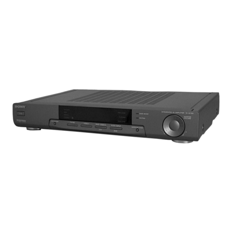
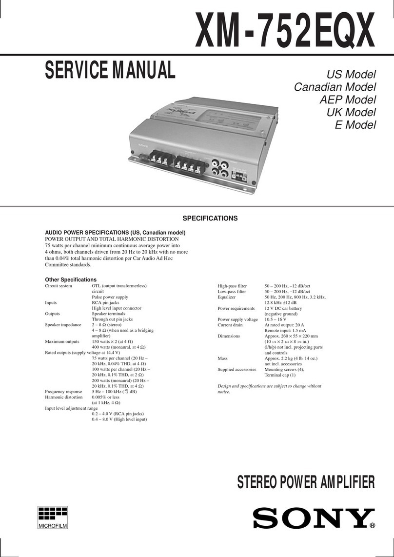
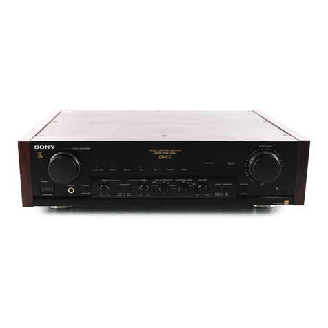
Sony TA-F606ES User manual

SERVICE
MANUAL
TA-FGOGES
US
Model
Canadian
Model
SPECIFICATIONS
Audio
Power
Specifications
POWER
OUTPUT
AND
TOTAL
HARMONIC
DISTORTION
:
With
8-ohm
loads,
both
channels
driven,
from
20-20,000
Hz
;
rated
80
watts
per
channel
minimum
RMS
power,
with
no
more
than
0.03
%
total
harmonic
distortion
from
250
milliwatts
to
rated
output.
With
4-ohm
loads,
both
channels
driven,
from
20-20,000
Hz
;
rated
100
watts
per
channel
minimum
RMS
power,
with
no
more
than
0.05
%
total
harmonic
distortion
from
250
milliwatts
to
rated
output.
Amplifier
section
Power
band
8
ohms,
_
width
THD
0.05
%
10
Hz
—
100
kHz
at
40
W
0.008
%
0.008
%
Dynamic
power
8
ohms
at
10
w
output
Total
harmonic
distortion
4
ohms,
at
rated
output
Intermodulation
|
(IM)
distortion
60
Hz:
7
kHz=
4:1
6
ohms,
at
rated,
output
8
ohms,
at
rated
output
Damping
8
ohms,
at
1
kHz
|
80
network
A,
8
ohms
Residual
noise
less
than
110
pV
PHONO
MM
(20
Hz
—
20
kHz)
RIAA
equaliaztion
curve
+
0.2
dB
Frequency
response
TUNER,
CD
TAPE
1,
2, 3,
DIRECT
IN
2
Hz
—
200kHz
*3dB
—
Continued
on
next
page
—
INTEGRATED
STEREO
AMPLIFIER
ON
Y.

TA-F606ES
0.25
mV/100
ohm
[MM
2.5
mV,
50
kilohm
TUNER,
CD,
DIRECT
IN,
TAPE
1,
2,
3,
ADAPTOR®
Input
sensitivity
150
mV,
20
kilohm
76
dB
(0.5
mV)
[Mm
|
93
dB
(5.0
mV)
TUNER,
CD,
DIRECT
105
dB
(150
mV)
IN,
TAPE
1,
2,
3,
150
mV,
1
kilohm
S/N
(network)
ADAPTOR,
AUX
REC
OUT
1,
2, 3,
ADAPTOR
Output
voltage
impedance
25
milliwatts
(at 8
ohms)
Accepts
low
and
high
impedance
headphones
BASS,
at
10
kHz
+7dB
Tone
contrels
TREBLE,
at
10
kHz
+7dB
Sihsonie
fee
a
ea
attenuation
below
HEADPHONES
General
System
Preamplifier
section:
Low-noise
high gain
NFB
type
equalizer
amplifier,
passive
type
direct
tone
control
Power
amplifier
section:
Pure-complementary
SEPP
MOS-FET
power
amplifier
Power
requirement
120
V
AC,
60
Hz
Power
consumption
U.S.A.
model
210
W
Canadian
model
300
VA
AC
outlets
2
switched,
total
120
W/1A
max.
1
unswitched,
120
W/1A
max.
Dimensions
Approx.
430
x
150
x
375
mm
(w/h/d)
(17x
57/,
x
14
%/,
inches)
Mass
Approx.
14.0
kg
(30
Ib
14
0z)
Design
and
specifications
are
subject
to
change
without
notice.
TABLE
OF
CONTENTS
Section
Title
Page
1.
GENERAL
Identifying
the
Parts
and
Controls
«-++-++++::
3
Hooking
Up
the
System
4
2.
ELECTRICAL
ADJUSTMENTS
=«..-:-----:--:
6
3.
DIAGRAMS
3-1.
[C803
System
Controller
(M
50720-358SP)
-:-
7
3-2.
Semiconductor
Lead
Layouts
-++++++++sreee:
8
3-3.
Circuit
Boards
Location
-rrrtrreesseeseece
9
3-4.
IC
Block
Diagrams
-+r+tttettre
sree sete
eee
9
3-5,
Block
Diagram
-+++tetsesr
eee
te
settee
eees
10
SAFETY-RELATED
COMPONENT
WARNING!!
COMPONENTS
IDENTIFIED
BY
MARK
A
OR
DOTTED
LINE
WITH
MARK
A
ON
THE
SCHEMATIC
DIAGRAMS
AND
IN
THE
PARTS
LIST
ARE
CRITICAL
TO
SAFE
OPERATION.
REPLACE
THESE
COMPONENTS
WITH
SONY
PARTS
WHOSE
PART
NUMBERS
APPEAR
AS
SHOWN
IN
THIS
MANUAL
OR
IN
SUPPLEMENTS
PUB-
LISHED
BY
SONY.
Section
Title
Page
3-6.
Printed
Wiring
Boards
(Control,
Input,
Selector,
Vol
Section)
-+-++---
13
3-7.
Schematic
Diagram
(Control,
Selectoe,
Vol
Section):
«+
+1*4
«sss
17
3-8.
Schematic
Diagram
(EQ,
Main,
SP
Section)
--+
21
3-9.
Printed
Wiring
Boards
(EO;
Main,
SP
Section)
ee
ee ee
ee
2
25
4.
EXPLODED
VIEWS
4-1.
Front
Panel
Section
Ce
28
AD»
BUC
Hangs:
“6
ees
oo
eerie
ae
acid
29
5.
ELECTRICAL
PARTS
LIST
-:---------:
31
ATTENTION
AU
COMPOSANT
AYANT
RAPPORT
A
LA
SECURITE!
LES
COMPOSANTS
IDENTIFIES
PAR
UNE
MARQUE
/\
SUR
LES
DIAGRAMMES
SCHEMATIQUES
ET
LA
LISTE
DES
PIECES
SONT
CRITIQUES
POUR
LA
SECURITE
DE
FONCTIONNEMENT.
NE
REMPLACER
CES
COM-
POSANTS
QUE
PAR
DES
PIECES
SONY
DONT
LES
NUMEROS
SONT
DONNES
DANS
CE
MANUEL
OU
DANS
LES
SUPPLEMENTS
PUBLIES
PAR
SONY.

SECTION
1
GENERAL
SAFETY
CHECK-OUT
3
Identifying
the
Parts
Fal
ale
R@rol
niice)
i<j
After
correcting
the
original
service
problem,
perform
the
following
safety
check
before
releasing
Mis'set
to
the
customer:
;
Remote
Commander
RM-S702
Check
the
antenna
terminals,
metal
trim,
‘“‘metallized”’
(Amplifier
control
section
knobs,
screws,
and
all
other
exposed
metal
parts
for
Input
selectors:
Select
an
input
source
of.
AC
leakage.
Check
leakage
as
described
below.
the
amplifier.
ATT.
+/-
buttons:
Control
the
volume
of
amplifier.
LEAKAGE
TEST
(2]Tuner//CD
player
control
section
t~<4/mb:
Locates
a
desired
section.
The
AC
leakage
from
any
exposed
metal
part
to
>:
Play
earth
ground
and
from
all
exposed
metal
parts
to
any
m:
Stop
:
:
PRESET
+/-
buttons:
Selects
a
preset
exposed
metal
part
having
a
return
to
chassis,
must
channel
of
the
tuner.
(for
the
not
exceed
0.5mA
(500
microampers).
Leakage
tuner
only)
SHIFT:
Select
the
preset
memory
page
current
can
be
measured
by
any
one
of
three
A,
Bor
C,
(for
the
tuner
only)
methods.
D.SKIP:
Move
to
the
disd
tray
next
to
the
current
one.
(for
the
CD
player
only)
1.
A
commercial
leakage
tester,
such
as
the
Simpson
229
or
RCA
WT-540A.
Follow
the
aoe
control
section
manufacturers’
instructions
to
use
these
instru-
</>:
Play
ments.
</>:
Fast
winding
m:
Stop
2.
A
battery-operated
AC
milliammeter.
The
Data
Pea
Precision
245
digital
multimeter
is
suitable
for
-
Sips
this
job.
3.
Measuring
the
voltage
drop
across
a
resistor
by
means
of
a
VOM
or
battery-operated
AC
volt-
meter.
The
“limit”
indication
is
0.75
V,
so
analog
meters
must
have
an
accurate
low-
voltage
scale.
The
Simpson
250
and
Sanwa
SH-63Trd
are
examples
of
a
passive
VOM
that
is
suitable.
Nearly
all
battery
operated
digital
RM-S702
multimeters
that
have
a
2V
AC
range
are
suitable.
(See
Fig.
A)
To
Exposed
Metal
Parts
on
Set
AC
0.15
uF
ae
voltmeter
(0.75
V)
—=_—-
Earth
Ground
Using
an
AC
voltmeter
to
check
AC
leakage.

Front
Panel
(JPOWER
switch
and
indicator
After
the
power
is
turned
on,
the
standby
indicator
lights
in
red
as
the
built-in
muting
circuit
activates.
When
the
amplifier
stays
in
a
stable
operating
condition,
the
indicator
lights
in
green.
The
indicator
lights
in
red
if
the
unit
detects
shorting
of
circuit
of
the
speaker
outputs
or
in
case
of
short-circuit
of
the
inputs
of
DC
components.
In
sucha
case,
disconnect
the
power
source
and
check
the
connected
components
and
speaker
systems.
(@JINPUT
SELECTOR
Selects
the
desired
program
source
for
listening.
(3}SOURCE
DIRECT
button
and
indicator
When
the
button
is
pressed,
the
indicator
lights
and
the
circuits
of
the
TONE
contral,
SUBSONIC
filter
button,
BALANCE
control
and
MODE
selector
are
disengaged
regardless
of
the
setting
of
the
switches.
(4]MUTING
button
and
indicator
Press
the
button
to
reduce
the
sound
level
by
-20
dB,
(Output
voltage
becomes
1/10.)
for
TA-F808ES/TA-
F707ES.
For
TA-F606ES
the
sound
level!
is
reduced
to
—e
dB
by
pressing
the
button.
Generally,
set
the
button
to
off.
(SJATTENUATOR
control
Adjusts
the
sound
level.
To
increase
the
sound
level,
turn
the
control
clockwise.
To
decrease
the
level,
turn
the
control
counterclockwise.
Note
;
Turn
down
the
sound
level
before
switching
on
the
unit.
This
prevents
damage
to
speakers.
[6]CARTRIDGE
LOAD
(TA-F808ES/TA-
F7O7ESVCARTRIDGE
(TA-F606ES)
selector
Set
the
selector
according
to
your
cartridge.
MM:
For
moving-magnet
type
cartridge.
MC:
For
moving-coil
type
cartridge.
40
Q:
For
a
cartridge
with
an
impedance
of
40
ohms
or
more.
(TA-F808ES/TA-F707ES)
3
Q:
For
a
cartridge
with
an
impedance
of
3
ohms
to
40
ohms.
(TA-F808ES/TA-F707ES)
[7JREC
OUT
SELECTOR
Selects
the
program
source
sent
to
the
REC
OUT
jacks
for
recording.
(8]BALANCE
control
Adjust
BALANCE
to
correct
stereo
imaging,
when
the
speaker
position
is
not
symmetrical.
(9]DIRECT
INPUT
selector
Set
to
SOURCE
to
select
program
source
with
the
INPUT
SELECTOR.
To
listen
to
a
program
source
processed
through
the
equipment,
such
as
graphic
equalizer,
connected
to
the
ADAPTOR
jacks,
set
it
to
ADAPTOR
(TA-F808ES/TA-
F/7O7ES)
or
SOURCE
(TA-F606ES).
To
listen
to
a
program
source
connected
to
DIRECT
IN
jacks,
set
it
to
DIRECT.
fig]
SUBSONIC
filter
button
if
subsonic
noise
components
created
by
warped
records,
etc.
are
present,
the
audible
range
frequencies
may
be
modulated
and
cause
irritating
intermodulation
distortion.
In
this
case,
press
the
button
to
reduce
noise
components
of
less
than
15
Hz,
which
cause
modulation
noise.
(WJMODE
selector
STEREO:
For
listening
to
a
stereo
program.
MONO:
For
listening
to
a
monaural
program.
fi2IBASS
and
TREBLE
TONE
controls
Adjust
the
tone
quality.
To
increase
bass
or
treble
sound,
turn
the
control
clockwise.
To
decrease
them,
turn
the
control
counterclockwise.
fi3]
SPEAKERS
selector
(TA-F808ES/TA-F707ES
only)
Select
speaker
systern
A,
B,
or
A
and
B.
To
drive
speaker
system
A:
Set
the
selector
to
A.
To
drive
speaker
system
B:
Set
the
selector
to
B.
To
drive
speaker
system
A
and
B:
Set
the
selector
to
A
+
B.
For
headphones
listening
only:
Set
the
selector
to
OFF.
To
use
a
power
amplifier
or
active
speaker
system
connected
to
the
PRE
OUT
jacks,
set
the
selector
to
B/PRE
OUT.
SPEAKERS
buttons
(TA-F6Q06ES
only)
Select
speaker
system
A,
B,
or
A
and
B.
To
drive
speaker
system
A:
Press
A
button.
To
drive
speaker
system
B:
Press
B
button.
To
drive
speaker
system
A
and
B:
Press
both
A
and
B.
For
headphones
listening
only:
Press
both
A
and
8
to
OFF
(f).
(14]
HEADPHONES
jack
Connect
the
stereo
phone
plug
of
headphones.
[15]
Remote
sensor

Hooking
Up
the
System
Notes
¢
Connect
the
AC
power
cord
last.
Make
sure
power
is
off.
«
Be
sure
to
connect
the
left
(L)
and
right
(R)
channels
consistently
between
equipments.
Fully
insert
cable
connectors
into
jacks.
Loose
connections
may
cause
hum
or
noise.
Connect
the
+
and
-
cords
of
the
speaker
systems
correctly
to
the
+
and
—
terminals
of
the
amplifier
respectively.
For
the
details
on
EY,
and
I,
see
pages
14
and
15.
Pour
les
détails
au
sujet
de
EN,
[4
et
@
voir
pages
14
et
15.
Graphic
equalizer,
etc.
Taner
Right
speaker
_—_
Left
speaker
Egaliseur
graphique,
etc.
Tuner
Enceinte
droite
Enceinte
gauche
YT
i
Lg
°°
LINE
IN
LINE
OUT
LINE
OUT
ae
CD
player,
etc.
CD
player
Lecteur
CD,
etc.
Lecteur
CD
|
oo
—
|
fg
FH
P
9
LINE
OUT
7
LINE
OUT
to
LINE
OUT
jacks
of
an
LD
player,
etc.
vers
les
prises
LINE
OUT
d’un
lecteur
LD,
etc.
E
=
to
a
wall
outlet
vers
une
prise
murale
to
the
second
speaker
system
vers
le
second
systeme
d'enceintes
LINE
OUT
LINE
IN
LINE
OUT
Turntable
system
Cassette
deck
2
Cassette
deck
1
Platine
tourne-disque
LINE
iN
Platine
a
cassette
2
Platine
&
cassette
1
A
pens
|
Df
—
C4}

SECTION
2
ELECTRICAL
ADJUSTMENTS
Bias
Adjustment
Note:
Adjustment
the
idling
after
tuning
the
unit
on
for
about
10
minutes,
giving
it
time
to
warm
up.
Procedure
:
1.
Connect
the
digital
voltmeter
to
VH4
on
main
board
sa
follows.
2.
Adjust
RT301(L-CH)
and
RT351(R-CH)
so
that
the
digital
voltmeter
on
signal
reads
24mV
at
VH4.
Adjustment
Location
:
{MAIN
BOARD]
—
COMPONENT
SIDE
—

SECTION
3
DIAGRAMS
3-1.
1C803
SYSTEM
CONTROLLER
(M
50720-358SP)
|
Pin
Name
[1/0
|
5V
CHECK
S/D
ON/OFF
PROTECT
X
OUT
X
IN
Description
Power
supply
(+5V)
check.
+5V
power
supply.
Ground.
Connected
oscillator
circuit.
Connected
oscillator
circuit.
Signal
input
for
a
return
to
normal
position.
Reset
signal
input.
(”L”
:
RESET)
+5
Volts
power
supply.
Connected
0.01yF
capacitor.
12
VOL
UP
13
VOL
DOWN
14
MOTOR
NORM
15
MOTOR
RVS
Volume
control
(up)
signal
output.
Volume
control
(down)
signal
output.
Motor
(normal
turn)
signal
output.
Motor
(reverse
turn)
signal
output.
16
Serial
data
input
(SIRCS).
17
Function
selector
positioning
detection
input
(PHONO).
18
Function
selector
positioning
detection
input
(TUNER).
19
Function
selector
positioning
detection
input
(CD).
20
Ground.
21
Ground.
22
Function
selector
positioning
detection
input
(AUX).
23
Function
selector
positioning
detection
input
(TAPE
1).
24
Function
selector
positioning
detection
input
(TAPE
2).
25
Ground.
CLOCK
DATA
LINE
MUTE
BRAKE
RELEASE
PHONO
Shift
register
for
LED
(CLK).
Shift
register
for
LED
(DATA).
Line
mute
signal
output.
O
O
Not
in
used.
Function
control
input
for
Phono
mode.
Function
control
input
for
Tuner
mode.
Function
control
input
for
CD
mode.
Function
control
input
for
AUX
mode.
Function
control
input
for
Tape
1
mode.
Function
control
input
for
Tape
2
mode.
+5V
power
supply.
+5V
power
supply.
Ground.
+5V
power
supply.
Ground.
oom
|
pe
efeen
tf
ee
ie

3-2.
SEMICONDUCTOR
LEAD
LAYOUTS
BA6208
2SA985A-QP
#HPC1237HA
28C02275A-P
Ss
Ss
7_f
+
{
C
Pa
123405678
B
m
TA7805S
2SA988-PAFAEA
2SA1371-E
28C2545-E
Eos
DTA114ES
DTC124ES
28A1175-FEK
28C2603-EF
letter
side
e
j
29SA733-QP
28C1941-LK
28C0945-P
28D774-34
EC
5
Ec
Bs
28C3423-0
2SK246-GR2
2SK1530-Y
2$J201-Y
HZS6C3L
HZS16-2L
HZL-7M1
11ES2
cathode
anode
IN4148M
cathode
anode
PC817
alg
Exel
30DF2
cathode
anode
SEL1516W
SEL2510C-D
SEL2810A
long
short
cathode
anode

3-3.
CIRCUITBOARDS
LOCATION
MAIN
BOARD
SP
BOARD
INPUT
BOARD
RYJ
BOARD
ABJ
BOARD
SS
INPUT
J
BOARD
SELECTOR
BOARD
(2/2)
——
|
aS
y
ZA
Ni
a
ae
4
see
Lr
H.P
BOARD
NG
EQ
BOARD
SELECTOR
BOARD
(1/2)
S
Yw>
VOL
LED
BOARD
CONTROL
BOARD
(1/2)
VOL
BOARD
CONTROL
BOARD
(2/2)
3-4.
IC
BLOCK
DIAGRAMS
1C501
UPC1237HA
IC807
M50253P
OVER
LOAD
DET

3-5.
BLOCK
DIAGRAM
DIRECT
=U
PJ4
(2/2)
(FUNCTION)A
nae
ah
IC404
41/2
va
ca
=
@401-402
‘ee!
by
|
O
'
1/2
PJU6
MGs
3404
Otc
PJ4(1/7
eae
4
CARTRIDGE
MM
TUNER
©
$204
SOURCE
‘
1
i]
1
1
1
!
1
1
i
a
i
!
i
'
i
!
'
1
1
'
1
!
1
i]
'
!
1
'
1
1
J
1
i
1
'
t
!
‘
t
'
1
f
1
!
1
!
'
1!
1!
1
.
1
1
1
i]
i
i
‘
'
'
i}
'
'
1
1
1
!
!
‘
1
1
1
i
J
t
i)
i)
4
'
1
'
!
'
t
t
!
L
AUX
O
DIRECT
PJ3
INPUT
O
DIRECT
;
IN
c
C
}
/ V
V
v
REC OUT
S
-
3102
PJ4
-
REC
OUT
7
SELECTOR
IN
|©
;
DAT/TAPE1
yyy
REC
OUT
[©
ee
-
PJ2
fie
hh
etd
ree
ea
Oh
$208
~+--}---------
7--->
RCH
/
D520
Icg
REMOTE
SENSOR
LO
ie)
2
TUNER
fe)
Qso6
CONTROL]
|S0
INVERTOR
are:
4.
M50720
S5Q3)
OUT
-358P
SC1
SYSTEM
CONTROL
Ics0e2
FUNCTION
MOTOR
DRIVE
D801-806
$801-806
Eel
TeNy
SWITCH
Q804
RETURN
SWITCH
RCH:SAME
AS
LCH
C7
/
ATTENUATOR
(A)
S20e-1,
3,
5
S208 S201
RV202-14
OFF
ARB
5
A
x
—1
ee
ae
E
RV201-1
BALANCE
D
S
ON
Ss,
~
~
~
=
RV203-1
s
ee
ee
ern
age
1
|
$203
eas
MODE
i
!
MONO
STEREO
i
o<«
/
AKR
-2
AKA
i
$205-2
|
RCH
MUTIING
Vv
ie
gee
Ue
ON
~
OFF
em
ee
ee
fn
ee
ee
ee
eee
ee
fee,
Ic808
(ISOLATOR)
B+
DB21-826
(FUNCTION
LED)
9-11°13-19
Q5-7,
ag-14
IC807
See
M5023P
LED
DRIVE
DATA
CLK
Voo
7)
S207
fess
|
Gf
Qs808
RY
DRIVE
B/PRE
OUT
RV204-14
ATTENUATOR
aso2
SWITCH
,
¢
XN.
ened
gq
3
It
;
x N
ON
€-
OFF
IC805
45
Vv
REG
1)
Q309-313
POWER
AMP
N
A
AT301
SS
cA
BIAS
(AT354:
ACH)
SPEAKERS
L
B
TERMINAL
NS
BOARD
(SP)
on
HEADPHONES
ICc504
uPC41237HA
HP
4
PROTECT
f
CIRCUIT
i
bt
/
Ww
O
/
wo
oa
8
/
bk
oO
/
peo
oO
te
fi
oO
KL
>wW
<
Oo
oa
/
D501-504
aia
abiats
cea
i
ole
¢
RECT
+55V
POWER
AMP
-55V
+55V
T4A
POWER
mee
TRANSFORMER
S601
3
POWER
eee
-15V
Q404
o——_{
AC
IN
+145V
REG
D505-508
3
iT
RECT
OFF
-55V
y
O
ON
D509-510
RECT
Dp810-813
RECT
TA-F606ES

TA-F606ES
6
i
8
|
,
[10
11
3-6.
PRINTED
WIRING
BOARDS
(CONTROL,
INPUT,
SELECTOR,
VOL
{INPUT
BOARD]
ii
a
Pa
eee
RARE
Ca
sa
a
2
:
m
i
aD
|
ee
ee
aay
Ma
oe
ae
ee
i
coy
anh
2
ae
Rate
fee
ats
.
te
st
Hi
2
Be
|
G2
ES
Be
fe
i i
Be
i
ue
2
oa
a
a
L
a
oe
:
:
beans
EB,
reat
A
:
He
ieee
i
2
aa
2
Bre
<i
i
.
iff
ee
He
i
es
Tae
a
Se
tily
ee
HE
i
ay
narasaraneonmae
ale
y
ee
a
ee
a
ney
oF
—
Hae
a
ces
i
:
Te
a
Ee
ce
i
a
Hinata
°
ng
ea
NH
ng
ey
a
ao
a
ce
Se
.
|
.
|
=
a
CC
a
_
a
:
|.
Le
a
8
i:
iantu
:
ae
oe
ca
i
Ces
me
FS
ca
a
=
:
|.
Ton
ee
cert
.
:
/
Ge
f
Bae
Ce
i
e
se
=
=
Se
eames
fi
ener
ince
ate
ina
He
ee
a
a
|
_._siéda_a_dw_éiédé4wiééwtéwtse
_
SP
BOARDICP17)
REE
EEE
ST
EEE
EE
ERTL
:
ay
&
Lia
ST...
a
ae
ff
,
ER
EE
a
Be
7
if
al
‘n
yey
asa
RT
MAIN
BOARDICP8)
crcolcst
cc
DIRECT
TP
ee
_
a
.
oe
SECTION)
ee
.
.
ey
LHe
RE
e
See
page
8
for
Semiconductor
Lead
Layouts.
{IPJ
BOARD]
vi
Jaco
cng
an
eo
(CHASSIS)
—
-—»
MAM
EG
BOARD
(CP
11)
fe
2
TRANSFORMER
LS
ea,
er
ean
-p520
Cas
POINT
13
1G
NG.
NN
20
a1
22
23
24
1-644
—
005
—
YS
_
eS
ns
2
gseatar
ans
PHT
pmnegioi
.
ain
a
Re
fis
He
Ae
fie
2
ae
f
ane
”
to
Perea
B
ae
ie
a
ie
EP
es
Ce
tae
rh
a
oe
Ee
Ceti
i
oe
ae
Ge
ve
BG
SS
a
ae
ee
im
Bie
Gea
ee
ie
Ls
ee
ee
a
ae
#
ae
ch
santa
Bae
i
ty
i
16
a
I:
a
bi
a
im
=
ss
te
Ss
ai
8
|...
aS
4
ae
Sane
|
(CHASSIS)
wv
EQ
BOARDIEH4)
j
i
4
1-644~-
006-
[VOL
BOARD]
—
a
1
ee
ee
ae
annatoa
omee
Sea
Si
ENTE
EG
RTA
ne
een
rf
io°)
i
Sk
a
+7
Se
Fi
pe
eee
see
za
©
ne
ea
Ge
:
7
is
Ei
z
i
if
oh
vf
if
i
{CONTROL
BOARD(I/2)]
>
|
ai
iE
vas
Ge
HPI
[HEADPHONES
|
L)
DIRECT
IN
({R}
(L)
(R)
20
[ADAPTOR]
(L)
Cw)
(R}
e
Semiconductor
Location
Ref.
No.
e@
o—:
Location
_
a
oo
I
moon
nen
-
-
1
i
ww
ow
Ao
Praga
igkr
reer
cas
GAT
Tare
ao
parts
extracted
from
the
component
side.
Pattern
on
the
side
which
is
seen.

3-7.
SCHEMATIC
DIAGRAM
(CONTROL,
INPUT,
SELECTOR,
VOL
SECTION)
©
See
page
9
for
IC
Block
Diagrams.
1
2
3
4
5
6
7
8
i]
10
11
12
14
15
16
17
18 19
20
21
22
23
24
25 26
and
tantalums.
Meee
ce!
ttn
hae
he
a
Ss
me
Ye
aN
ney
csi4
To
RA
we
ithe
sot
ae
Botta
UF
oe
ee
ee
ae
ee
7
ch
fs:
ms
ee
a
-
os
=
>
teece
Z a
a
a
“3
-
im
[(zNeUT
BOARD)
om
EQ
BOARD
[[seLectonr
BOARD
(1/2))
Beat
eae
PCBi7
'
cP4i
Rig
.
§
+4
=
=<
C=
:
x
ol
(pea:
Deze
Dees Da26
ROBES
cS
|
j
oI
=
(PHONO)
(TUNER)
(AUX)
(DAT/TAPE
4)
82
Sn
ee
a
ee
ea
1
Pu2-4
mrepsof
,
Jerse
Son
cits
:
DAT/TAPE’|
(O}-—4
4
jo}
>
i
ete
0
0
.
i
(IN)
é
>>
O
O
)
40,3
pys-3
Ty
eet
Pk
|
se02
oS
raat
IC808
'
Pron
en
ane
O—-
ot
tol
CD
i
es
ah
als
S(POWER)”
ree
|
|
i
[VoL
LED
BOARD]
Mo4
ae
lof
tof
tol)
cts
D827,
828
BEAUE
USE
!
?
To!
Pui~4
en
-4
Pisa
lol
—lo}
——toh]
Lik,
0 0
SEL2B10A
[ge
o-F
AEC OUT
lof
tof
toh)
'
[co]
cei4
28
4)
i
Af
ra
kd
(IN)
ee
op
fob
for
|
ood
cis
ee
LED
DAIVE
E 3
|
249
(T-¥:)
:
SEL2510C
-
THIO
pus-4
Se
OAT/TAPES>
2
eee
[aux]
aie
ug
5
Benes
|
aie
)
i
O °
' '
Paneer
ener
nh
Sem
eet
O-4
TAPER
+
4
5
Bl
eB
n
O
eu
Bis
tet—
heh
se0e
gai?
°
AUX
a?
7
Ohh
13h
oO
0
0.04
a
a
ae
cb
core
_
SELECTOR
]}!
|
a
EI
SST
ei
oo
INPUT
J
dees
TUNER
ada
Oo
6°
BOARD
(2/2)
‘
rane]
LY
Bene
NN,
BOARD
\
ee
mecoon
O-F
S:
|
|
! 1
(REC OUT)
4
|
L——-—_--
—-
[90
8
8
FF
5
9)
ee
CXXEEEEx
SS
et
trem
-
xx
ee
O
i
TCEcEG
1
a(((
(ll
ff
_=
_
—
(CHASSIS)
CP&6
ee
SS
a
a
a
aia
ic
ea
Se
|
ae
ar
poate
eee
19-9999
9
9
9]
—_———
EE
ee
ne
eee
=
a
a
eo
See
See
RYJ
DAT/TAPE4
ee
|
A
CONTROL
|
<=
[ore
akens|
——
BOARD
To
PJ3-6
rt.
i
87654321
BOARD
(4/2)
>
o—?
=
Se
eet
SP
BOARD
-2
|
akR
|
CRESTS
s1c9
=)
Pui=3
D>
|
-4
R379
Rag9
(CHASSIS)
ina
ve
~-2
—
mar
reecnr-svsrmenesmneren-nerrepcrmpeatat
mere
pew
abo
bh
ab
go
-
ee
470
ANCA
MB.
[TaPea]
470
C87
aaa
>
1
ae
eee
Tr
|
necoS
|
wyene
oun)
|
or
2M
sew
1)
yt]
yah
TY
aa
:
:
a
at
:
:
acer
[acxd
>
{
|
(4BH2)
ee.
RBBO
3.9k
1/2W
RB46
3.9k
1/20
on
!
et
fof
Io]
-
'
O
O
O
on
7
3
1
|
a
pees
ae
|
es
ae
em
Puin4
TO
3
|
|
|
|
Dorr
|
PEt
RU)
Bw
sone
nies
:
|
! !
:
Fc
oom
R~CH!
$
CONTROL
ba
i
De
oe)
t__.
SAME
AS
_L-CH,
'
BOARD
(2/2)
ot--fop
tol}
>
ED
ED OD
ES
OD OD GD
EP GD GP GH OD OE US ED
ED
ED
OD
Gb
HD EE EP ED
CD
GD
OD
GO OD
ED
EP GD OD
CD
OD SD
OD BE ED
GD GP
OD ED OD
GP
EP ED
GP
ED
EP
OD
OD
OF OO
ED
OD OD OD 1D
OD OD
OD
O
i
oscil
aasiataemeeteniatiemnienelininaticeneaaiiidemeineenemedlictedel
1
fe
ne
|
t
©
O O
Di KR
Pe
cman
id
oe
er
el
RY)
tRansronnen
lot
—fol
——
Si
T4A
'
lot
tol
mm
eh
Phy
e®
aio
CPt
ru
AV204
RV202
RV203
CURRENT
fy
ae
w/EHS
[FReece]
—
tone)
—
[ass]
1
Cae
ba
Be,
180k/
150k
250k
250k
25k/500k
p°
284733
ry
bd
os
0
00
00
0
00
Oo
an
an
a
om
wm
cay
em
nm
om
a
ee
ne
ww
wm
em
hm
er
re
rm
sr
00
0
em
0
om
em
ne
a
a
a
on
nr
08
or
oy
RELAY
EH2
;
H
DRIVE
1
@810
1
H
FILTER
4
51.2
280774
'
|
'
'
52.3
%
-L-CH-
[prREcT]
©
H
28c2603
DIRECT
'
RELAY
TIN)
;
!
H
SWITCH
8204
pa1e
me
KP
RYBOt
{T4148M
$202
A-CH:
H
1N4148M
SOURCE
H
bass
ee
————
Sane
AS
th
'
QLorect->
[1
source
agus
ay
7
ON
+
OFF
TO
'
E@
BOARD
'
EHs
‘
a!
1
RV204
|
t
!
[arenuaror}
«=
ou
=
t
H
120k/120k
|
NY,
:
1
0
a0
om
00
em
a >
chp
OP
Ott
OD WP Ot
Wi
UD
Wid
md in
OH
Cae
ed
Ca
ed
oe
Oar
Ute
et
ate
eal
ead
a0
ey xD OD
Cd
OD
CD
ad
ow
aD
om
ew
awe
ow en
alam
wD
Has
am
eH
mammagy
ft
-R-CH-
f
Cee
ees
a
aS
a
-
ee
RE
ae
|
(IN)
.
a
i
i
1
‘
'
-
‘
we
t
(IN)
—
a!
|
’
!
|
}
R-CH:
'
D801-806,
808
(OUT)
SAME
AS
L-CH,
1
t
Lo
{N4448M
q
8
7
i
5
4
3
oe
Oe
a
On
a
ON
OP
LO
ROO
OR
Ne
ED
wen
oe wr ee an an
fe
er
ew
en
ins
en
fom
on on
owen
af
Vv
MD
lon
|
:
any
RB21
SAB20
S$
AB19SAB1B
SABL7
SABIG
naan
nD
haga
D806
10k
F
40k
F
10k
F
40k
F
10k
i
t
:
mn
me
ness
Bie
Ge
ie ee ae
eee
ee
ee
bs
Cis
10k
aay
Oe
ee
ee
eee
eee
AY704
rey
{N4448M
_
pa03
=]
SS
:
aa
i
os
Cah
ee
cS
ee
s
anedd
|
|
:
Bi
Eine
Da0%
@
All
capacitors
are
in
wF
unless
otherwise
noted.
pF:
uuF
tc
8
eee
sior
LS
7
(FUNCTION)
5
gX7
EU
ee
SOWV
or
less
are
not
indicated
except
for
electrolytics
e*
4
AUX
‘
TAPE2
DAT/TAPE1
+
PHONO
ARESERE
12
9
9
9
9
9 9
9
CEERBEEEE
fr
w
r
t
1
t
4 J ' '
'
1
4
'
4 1 i 4
t]
$ 4
' '
'
t '
1
\9
S
$208
SOURCE
OIRECT
ON
*
¢
TUNER
2
ry
x:
RANA
t
t
4
4
4
4
‘
i]
4
’
4
4
'
’
1
cp
;
™
)
t
'
t
’
'
'
t
'
’
'
t
t
'
t
i]
‘
t
i]
1
OFF
2
M
Q804
'
BN1A4M
i
jo
RETURN
1
oa
4
fo
9806
SWITCH
Cc
1
O86
.
BASF
4M
Ons
7
&
|
INVERTER
2
i)
~
12k
MOTOA
DRIVE
(ATTENUATOR)
og=%*
74
MOTOR
ORIVE
($104)
Ics0a
BA6208
oo
|
i
@803
23C260
RESET
(-¥:%-F}
450720-3589P
SYSTEM
CONTROL
C@04
0.01
IC
805)
TA78053
0810-813
11ES2
+
.
SV
REG
RECT
IC804q
TA78058
+BV
REG.
|
if
e@
All
resistors
are
in
2
and
!/,W
or
less
unless
otherwise
specified.
e
few
:
nonflammable
resistor.
e
{w
4:
fusible
resistor.
Note:
The
components
identified
by
mark
Aor
dotted
line
with
mark
A
are
critical
for
safety.
Replace
only
with
part
number
specified.
@
mem
.
Bt
line.
®
eames
©
B-
line,
©
:
adjustment
for
repair,
e
Voltage
and
waveforms
are
dc
with
respect
to
ground
under
no-signal
conditions.
©
Voltages
are
taken
with
a
VOM.
(input
impedance
10M22)
Voltage
variations
may
be
noted
due
to
normal
produc-
tion
tolerances.
®
Signal
path.
e5>:
PHONO
TA-F606ES
o7
|

3-8.
SCHEMATIC
DIAGRAM
(EQ,
MAIN,SP
SECTION)
e
See
page
9
for
IC
Block
Diagrams.
1
2
3
4
5
6
7
8
9
10
11
12
13
14
15
16
17
18
19
20
21
22
23
24
25
26
27
(Eq
BOARD]
5
5
[[MAIN
BOARD)
“caus
I
ee
ee
ee
Sa
eis
:
54,
[SP
BOARD]
t
|
I
33p
@312.
343
z
Q310
Ane
POWER
AMP
T™™900
asc2e75
«0
CURINGTON
SPEAKERS
|
'
‘
R317
a312
CAHREGSNEE
A
ee
ve
ace
47
1/72W
8Ki53
o,
yi
55.4
23K
2530
seats
!
R324
PROTECTION
1
t
’e
|
1N4148M
Pane
‘
-4
|
B
0307
;
!
@302.
303
Sas
|
ihagaau
254988
CURRENT
@307
CASCADE
H
H
:
L
MARROR 284916
NY
:
os
'
H
4
a)
a
~
1a
csi
P2P
So!
~a
——+fot
tof
_th
ol
to!
Ng
7
ess_to|
L|—__L}_
1]
Hi
!
aaan
fot
fof
fof
fo}
1N4148M
NF,
'
RYSO3
(A)
C
CP17
\
2802259
DIFFERENTIAL
@305,
308
|
-65.5
oe
o
O O
2
Fl
ena
sue
CONSTANT
cer
er
Pere
N41
40M
@)<_fol!
Less
as
.
6)
we
CURRENT
aaa
OS
ed
ORR
Wes
a
De
HP
a
a
ee
;
:
as
ae
rah
an
Se
R07
em
0
GD
Dosh
0313
Lane
el
seen
a7
S
eI
27k
12M
RR
4
Oa
De
BD
re
SY
eels
Nabe
3
TO
ME)
A306
eee:
(a
ae
Fs
Ee
9
CS
a
a
aE
VOl.
BOARD
12
220
ascisat
[fit]
Ty
TTT
Ch
aa
ea
R
EH4
>
11
OL.
oe
i
bd
y
c30e
-53,3
10
10 10
be
eR
i
479
a
CP413
cptal
i
ee
a
eee
he
Za
|
|
f
aBs
3
D
Reet
BOARD
|
C304
a
Loops
A302
'
£00
i
|
Q304
1
OS
ff
iy
CONSTANT
C348
A326
|
a
|
CURRENT
7
100/50V
100k
1/2W
c341
cio
|
'
r
7
.
'
one
C347
+
470/63V
470/63V
|
t
NZ
L
D
|
1/20
5p
+
|
Pe
|
{
i
roe
c309
|
VA,
'
0.04
{
:
|
Pome
nen
enter
nnn
nnn
enn
n
nnn
mene
nnn
nnn
nen
nnn
n
ener
nnn
nnn
enn
wenn
nent
ewer
ween
en
ennennn
enon
nnn
e
mene
nnnnn
nn
|
H
'
‘
i
;
'
|
(B)
'
t
‘@
a356
:
‘
'
AS
}
i
|
‘
4
!
¢
H
'
R-CH:
0516
E
H
fy
'
'
1N4148M
{
Gane
‘
1
SAME
AS
L-CH
'
LR.
H
|
OOS
EMO
SOMEONE
TSE
MN
UEMeE Enema
me
newmwn
Sree
memo
man
Oo
tee
On an em
Oe
OF
OO
0
oe
ae
a
ee
ae
ee
a
a
ew
oe
emer
wemuad
i
'
H
'
'
@355
'
Ss
1
~
'
A381
’
'
PROTECT
1
ey
‘
ICBOt
1
{
CIRCUIT
H
H
'
ePCL2A37HA
§
A358
'
i
i
'
|
F
t
C)
9358
'
Ah,
'
‘
‘
8
i
t H
|
1
to
+
fp
{
|
}
A-CH!:SAME
AS
L-CH,
:
t
3
‘
3
|
4
|
'
OP
Ae
6
OP
OO
SP
AP
A
Ha
aD
HP
Ent OHO
SD
OOP
POD
OP EP OP
OEE
DS
SF
OH OD
SP
SD
SOY
SD
OP
ED OA AP
OD
Oa
OR
OOH
SUD
SO
SD OH OP
SD
Om
OND
OAD
OP
OP
OID
ED
SPD
SD
OO
OTP
SD
OEP
DD
NO HP
SED
SED
SD
OD
OU
OD
OO
OD
OP
AED
ED
OP
HED
OD
ED OD
EP OD
EP
AED
OD
OD OP OD
Hn
OY
aD
OD
OW
H
5
0403
a
|
280945
peel
o
:
G
i
@403
cpa
o
|
+45V
REG,
E
aba
4
To
of
—4
1
;
f
RYU
BOARD
Um
\
pea
6810
To
-45V
REG,
|
4
ee
|
Nha
H
|
{
5
'
|
[AA
peot
42
D514
14682
D610
11
E2TAZ
|
100/35V
iene
|
\ H
D509
11E2TA2
VHA0
H
{
| |
i
f
|
R425
R426
R427
VH
|
:
820
1/2W
8201/2W
820
I/2W
~555
1
0
505-508
soma
~
en
———
-
em
O
L1E2TA2
Pe
nn
er
re
en
re
eee
eee
nee
O--
3
!
Q4o4
v
O
RECT
A\
Qo
|
|
284733
“24,4
nar
T4A
x!
See
i
POWEA
|
ae
i]
‘
!
TRANSFORMER
NOT
REPLACEABLE!
]
(CHASSIS)
00g
g00900090
00090099
0900
0
9
BUILT
IN
TRANSFORMER,
|
ic
aot
|
ae
:
q
4
{
7
a
t
NJM4560D
D404
{
b
d.--
|
PHONO
AMP
UZL7M1
cP414
(A)
94014,
402
65
>
6
a
EQ
AMP
io,
INPUT
BOARD
(F)
RYJ
S0ARD
\
caoe
2802545
eee
aan
Note:
baal
.
pay
Cr
C501-804
e@
All
capacitors
are
in
wF
unless
otherwise
noted.
pF:
pur
aor
aecke
50WV-or
less
are
not
indicated
except
for
electrolytics
and
tantalums.
e
All
resistors
are
in
2
and
1/,W
or
less
unless
otherwise
specified.
e
fend
:
nonflammable
resistor.
e
fw}:
fusible
resistor.
Note:
The
components
identified
by
mark
A\
or
dotted
line
28C2545
C404
C405
Ae
a
hig
0.056
0.016
100
C508
0.47/160V
}
Ratz
R418
|
BBk
1/2
4.7k
1720
7
e
-
So
oe
ee
with
mark
/A\
are
critical
for
safety.
PJ6
sek
ka
Seda
8
se
es
ee
ge
yee
al
Replace
only
with
part
number
specified
UeV
,
YWY
2
P
ae
(CHASSIS)
fium
—>
Ome
sik
=
=
a =
ae
- = e
a
=
ms
~
=
ce
<
>
sot
¥
-
:
©
emma
.
Bt
line.
auveeueounsuccccoslceenewceuceo=ses
‘Secseweccenccoce
Beecetecceweccs
SdSsbcesecudcéaciaddedsavmacccadeecaccuccanccuceoncsce
<
©
eeapen
~
B-
line.
e
[]
:
adjustment
for
repair.
©
Voltage
and
waveforms
are
de
with
respect
to
ground
under
no-signal
conditions.
e
Voltages
are
taken
with
a
VOM.
(input
impedance
10M)
Voltage
variations
may
be
noted
due
to
normal
produc-
tion
tolerances.
Q451
Q452
Ca
e
Signal
path.
eBSS>:
PHONO
R~-CH:
v v
SAME
AS
L-CH,
ay,
=8
uy,
0
8
at
OO
OO
OS
OE
OW
OO
OO
ORO
OCHO
SSSS
DSS
SHOSSRODOEMSNMSEmemwemaamdl
TP
et
4
tae
aes
oe
S218
er

TA-F606ES
3-9,
PRINTED
WIRING
BOARDS
(EQ,
MAIN,SP
SECTION)
e
See
page
8
for
Semiconductor
Lead
Layouts.
eee
atv
[toaton
[fo
to
[ention
1-10
{
2
3
4
[|
5
[|
6
|
7
|
86
[|
9
|]
11
12
B
14
15
6
|
i
[|
6
|
‘19
20
nn
ae ae
co
l
T9200
©
!
$401
VOL_B
sct
O—
§
—_
6
CC
——
{EQ
BOARD)
eon
‘Hinge
aie
:
[TUNER
CONTROL|
ae
Poa
o1
o>
I
(OUT)
oo
I
{OUTLET
BOARD]
oO
t
nm
t
oe
>
OF
01
O1
C405
qa
t
oO
I
ae
YyYwwWaadaani
ft
?
[SP
BOARD)
iw)
q
o>
!
o>
t
a]
Ul
a
7
orp
Pp
near
POP
G& Gd
Cw
a]
1
mn
I
an
1
oD
i
a
Oo
OO
Wf
PrP
mn
}
qQ
!
ern
PO
PM
he
oO
AC
OUTLET
Om
@
—
~
_
_
i
if
a.
i
A
|
_
a
.
fn
i
4
en
hal
.
a
i
ae
—
7
a
a
—
a
—
_?
_.
.
-
|.
_
-
—
_
|.
—
A
ao
ae
2
.
-
.
_
|
wn
4
ae
i)
a
a
ae
7
a
ae
y
2
Secs
an
fi
fe
Hi
i
ie
_
2
|
oo
oo.
.
i
_
_
.
oe
HY
“
a
a
_
_
-
7
-
-
|
_
_
|
a
<=
—
,
a
—
|
o
a
j
<.
i:
.
._
aa
——n)—
t
oOo
{MAIN
BOARD)
|
a
Ly
i
|
~
oe
ft
a
INPUT
BOARD
(C814)
0-7
B-3
D-8.
C-
i
i
i
pay
-
,
|
7
c
iar
neh
Hl
eae
y
LL
RYJ
BOARD
C-
(
ee
y
—
if
i
iy
a
an.
ge
—
_.
{cS9)
®
i)
i
el
ag
UT
a
a
—
acre
nur
comracrnen
npg
pecan
:
|
.
_.
a
d
y
-
ett
eG
ee
et
a
EE
a
a
ee
ete
an
tae
ed
5-998.
i
-
0-
[11]
AAT
ts
—
te
a
:
—
oa
fa)
—-
-
F-
.€
50-008
)
fT]
SaaS
ee
SS
aS
Se
Se
SS
es
ee
SS Se
eee
See
_
-
G-
|
»
"
ae
.
aT,
Ht
Pe
i
-
ty
|
_.
i
a
Hf
6
-
"
x
i
eth
i,
aie
j
oe
|
|
cs
;
/
i
7
—
ar
ce
A
i
|
ae
of
.
u
=
68
-
a
G
eo
|
@
Tadic
|e
4
=
—
PATH
iy
tos
a
/
2
|
a
a1
/
a
i
-
ae
A
lb,
i
ae
—
:
le
:
|
te
A
Lo
er
/
A
Be
.
.
LL
|
a
_
_
ow
1
{
mon
Ooowo—
nT
OW
WO
WW
WwW
WwW
Ou
(HEAT
SINK)
ie
Mf
4
iy
t
—-
—-
OoODmDoaonwnmdmrh
ann
Se
a
ee
ee
ae
ae
op
1-644-007
aaa
dads
lar
re
~
i}
2
|
=
'
=
|
!
=
|
i
S
!
|
Sng?
|
|
|
'
(not
REPLACEABLE:
|
<3)>—
BLU
BUILT
IN
TRANSFORMER
u
I
|
:
'
4
i)
|
RYJ
BOARD
<4
BLU!
|
|
(EHS)
bi—.--—-——--
T4A
POWER
TRANSFORMER
\--)---------
i
a
a
Na
a
Ne
=
=
=—sN
|
|
A
|
2
I
3
Y
-
see
Y
L
Tohono
Pa
ey
{ABJ
BOARD]
Note:
:
parts
extracted
from
the
component
side.
Pattern
on
the
side
which
ts
seen.
/
1-643-997
P
@
RYJ
BOARDICS10)
(CHASSIS)

NOTE:
@
-XX
and
-X
mean
standardized
parts,
so
they
may
have
some
difference
from
the
original
one.
®
Color
Indication
Example:
KNOB,
BALANCE
(WHITE)...
(RED)
t t
Cabinet’s
Color
of
Appearance
Parts
Parts
Color
4-1.
FRONT
PANEL
SECTION
8
9
Ref.
No.
Part
No.
Description
4-955-303-21
LID
4-942-226-01
ARM
(R)
4-942-225-01
ARM
(L)
4-879-274-01
SPACER
X-4942-633-2
PANEL
(BASE)
ASSY
ot
me
©
BD
Re
4~942-233-01
SPRING
(L),
PLATE
4-942-234-01
SPRING
(R),
PLATE
4-$62-278-01
PANEL,
FRONT
*
&
wonrw
oe
SECTION
4
EXPLODED
VIEWS
@
items
marked
“**”
are
not
stocked
since
they
are
seldom
required
for
routine
service.
Some
delay
should
be
anticipated
when
ordering
these
items.
@
The
mechanical
parts
with
no
reference
number
in
the
exploded
views
are
not
supplied.
e@
Hardware
(#
mark)
list
is
given
in
the
last
of
this
parts
list.
Remark
Ref.
No.
Part
No.
Description
The
components
identified
by
mark
A\
or
dotted
line
with
mark
A\
are
critical
for
safety.
Replace
only
with
part
specified.
number
Les
composants
identifiés
par
une
marque
/\
sont
critiques
pour
la
sécurité.
Ne
les
remplacer
que
par
une
piéce
portant
le
neméro
spécifié.
Remark
§
4-931-646-01
LENS,
LED
10
4-952-206-01
WINDOW,
REMOTE
CONTROL
11
3-704-366-01
SCREW
(CASE)
(M3X8)
*
12
4-946-347-01
CASE
14
4-951-620-01
SCREW
(2.
6X8),
+BVIP
15
1-644-004-11
SELECTOR
BOARD
16
4-951-921-01
BUTTON
(F)
17
4-942-568-01
EMBLEM
(NO.5),
SONY

4-2.
SUB
CHASSIS
54
not
supplied
supplied
with
HP1
supplied
with
RV201-203
sk
(including
A)
“A
#2
ee
52 ee
(including
A)
#2—_
7
aa
eo
ee
ee
a
67
66
Ref.
No.
Part
No.
Description
Remark
Ref.
No.
Part
No.
Description
Remark
51
X-4944-218-1
KNOB
(DIA.
52)
ASSY
*
61
4-916-782-21
DAMPER
52
4-§52-955-01
KNOB
(DIA.
13)
*
62
4-908-892-01
SPACER
53
4-952-954-01
KNOB
(DIA.
13)
§3
4-946-338-01
ROD
(C)
54
4-942-032-01
KNOB
(POWER)
64
4-942-228-01
KNOB
(3X13)
55
4-946-340-01
ROD
(P)
65
4-951-922-01
JOINT
(SD)
56
1~644-006-11
HP
BOARD
66
4~-931-926-01
BUTTON
(B)
57
1-692-138-11
SWITCH,
ROTARY
(REMOTE
TYPE)
67
1-644-005-11
VOL
LED
BOARD
*
58
A-4347-853-A
CONTROL
BOARD,
COMPLETE
68
4-946-335-01
BRACKET
(BEARING)
*
59
3-350-846-51
HOLDER,
PCB
69
4-946-331-23
SHAFT
(VOL)
60
4-931-641-01
BUTTON
(DIA.
4)
70
4-9§3-475-01
COLLAR

4-3.
MAIN
CHASSIS
LA,
A
not
supplied
not
supplied
(Canadian)
#8
not
supplied
Ref.
No.
Part
No.
Description
Remark
Ref.
No.
Part
No.
Description
Remark
*
101
A-4365-596-A
EQ
BOARD,
COMPLETE
116
3-706-165-00
SCREW
102
1-644-001-11
VOL
BOARD
117
4-923-882-02
RING
(LARGE-16),
ORNAMENTAL,
FOOT
*
118
4-923-850-01
FOOT
(DIA.
48)
119
4-916-782-21
DAMPER
121.
4-916-732-01
BOARD,
BOTTOM
103
1-644-002-11
INPUT
J
BOARD
104
1-644-000-11
ABJ
BOARD
*
105
A-4365-595-A
MAIN
BOARD,
COMPLETE
*
*
106
1-644-008-11
INPUT
BOARD
122
3-942-525-01
BLIND
(1),
KNOB
107
4-946-329-01
RETAINER,
ELECT
CAP
123.
4-946-336-01
BRACKET
(GROUND)
108
1-643-999-11
RYJ
BOARD
124
3-655-653-21
BAND
(TAITON),
BINDING
109
1-644-007-11
SP
BOARD
*
125
1-650-098-11
OUTLET
BOARD
*
110
4-951-917-41
PANEL,
BACK
126
=
1-573-905-11
PLUG,
JAMPER
*
111
|
4-$23-873-01
BRACKET,
CORD
STOPPER
ACP1
—-1-575-975-11
CORD,
POWER
*
112
3-703-244-00
BUSHING
(2104),
CORD
A\T4A
—-
1-423-873-11
TRANSFORMER,
POWER
113
4-963-475-01
COLLAR
(US)
Note:
Les
composants
identifiés
par
une
marque
A\
sont
critiques
pour
la
sécurité.
Ne
les
remplacer
que
par
une
piéce
portant
le
neméro
spéci-
fié.
Note:
The
components
identi-
fied
by
mark
A\
or
dotted
line
with
mark
A\
are
critical
for
safety.
Replace
only
with
part
number
specified.

SECTION
5
ELECTRICAL
PARTS
LIST
NOTE:
Due
to
standardization,
replacements
in
the
-
parts
list
may
be
different
from
the
parts
specified
in
the
diagrams
or
the
components
used
on
the
set.
-XX
and
-X
mean
standardized
parts,
so
they
may
have
some
difference
from
the
original
one.
RESISTORS
All
resistors
are
in
ohms.
METAL:
Metal-film
resistor
METAL
OXIDE:
Metal
Oxide-film
resistor
F:
nonflammable
Ref.
No.
Part
No.
Description
*
1-644-000-11
ABJ
BOARD
Ae
oR
KK
KK
<
CONNECTOR
>
*
(P12
1~568-202-11
PIN,
CONNECTOR
(PC
BOARD)
10P
*
(P13
1-568-202-11
PIN,
CONNECTOR
(PC
BOARD)
10P
Items
marked
“>”
are
not
stocked
since
they
are
seldom
required
for
routine
service.
Some
delay
should
be
anticipated
when
ordering
.
these
items.
SEMICONDUCTORS
In
each
case,
u:
wz,
for
example:
ABJ|
|
CONTROL!
The
components
identified
by
mark
A
or
dotted
line
with
mark
A\
are
|
critical
for
safety.
Replace
only
with
part
number
specified.
Les
composants
identifiés
par
une
ooo
ook
io
oioi
iodo
iio
iio
kok
ioloiokiok
doko
fo
kok
ik
~A-4347-853-A
CONTROL
BOARD
oS
tetok
bk
<
CAPACITOR
>
(201
1-130-472-00
MYLAR
0.0012uF
5%
¢202
1-130-480-00
MYLAR
0.0056uF
=
5%
¢203
1-130-479-00
MYLAR
0.0047uF
=
5%
€204
=
1-136-159-00
FILM
0.
033uF
om
C206
=1-136-169-00
FILM
0.
22uF
o%
0251
=
1-130-472-00
MYLAR
0.0012uF
5%
¢252
=1-130-480-00
MYLAR
0.0056uF
5%
¢253
=
1-130-479-00
MYLAR
0.0047uF
=
5%
(254
=:
1-136-159-00
FILM
0.
033uF
Hyd
(256
=1-136-169-00
FILM
0.
22uF
Hyd
C801
1-130-483-00
MYLAR
0.
OluF
om
C802
1-161-379-00
CERAMIC
0.
OluF
20%
C803
=
1-126-059-11
ELECT
10uF
20%
C804
=1-161-379-00
CERAMIC
0.
OluF
20%
C805
1-161-379-00
CERAMIC
0.
O1uF
20%
C806
1-162-282-31
CERAMIC
100PF
10%
C807
=1-162-282-31
CERAMIC
100PF
10%
C808
1-136-165-00
FILM
0.
luF
yd
C809
1-124-999-11
ELECT
2200uF
20%
C810
=
1-126-059-11
ELECT
10uF
20%
C811
=
1-126-059-11
ELECT
10uF
20%
C812
=
1-126-062-11
ELECT
47uF
20%
C813
=
1-126-058-11
ELECT
4.
7uF
20%
C816
=
1-126-
163-11
ELECT
4,
TuF
20%
<
CONNECTOR
>
CP6
=
1-695-015-11
PIN,
CONNECTOR
(PC
BOARD)
8P
CP7
=
1-695-015-11
PIN,
CONNECTOR
(PC
BOARD)
8P
PB.
@
PB.
UG.
LPC...
marque
A\,
sont
critiques
pour
la
uPD...:
PD...
Ne
les
remplacer
que
par
une
piéce
CAPACITORS
portant
le
neméro
spécifié.
uF:
UF
COILS
When
including
parts
by
reference
uH:
“WH
number,
please
include
the
board
name.
Remark
Ref.
No.
Part
No.
Description
Remark
CS4
1-568-319-11°
SOCKET,
CONNECTOR
8P
CS5
1-568-319-11
SOCKET,
CONNECTOR
8P
CS6
1-568-319-11
SOCKET,
CONNECTOR
8P
CS7
°1-568-117-11
SOCKET,
CONNECTOR
14P
EH2
1-564-517-11
PLUG,
CONNECTOR
2P
<
DIODE
>
D801
8-719-987-63
DIODE
1N4148M
D802
8-719-987-63-DIODE
1N4148M
D803.
8-719-987-63
DIODE
1N4148M
D804
=:
8-719-987-63
DIODE
1N4148M
D805
«=
8-719-987-63
DIODE
1N4148M
50V
50V
D806
=©8-719-987-63
DIODE
1N4148M
50V
D807.
8-719-987-63
DIODE
1N4148M
50V
©
D808
8-719-987-63
DIODE
1N4148M
50V
D808
8-719-987-63
DIODE
1N4148M
D810
8-719-200-82
DIODE
11882
S0V
50V
D811
=8-719-200-82
DIODE
11ES2
50V
D812
=©8-719-200-82
DIODE
11ES2
50V
D813
=
8-719-200-82
DIODE
11ES2
50V
D816
~8-719-987-63
DIODE
1N4148M
D817
+=
8-719-987-63
DIODE
1N4148M
30V
25V
D818
8-719-987-63
DIODE
1N4148M
25V
25V
<
IC
>
25V
1801
8-759-962-08
IC
BA6208
50V
1¢802
8-759-962-08
IC
BA6208
50V
1¢803
8-759-082-11
IC
M50720-358SP
(SYSTEM
CONTROLLER)
50V
1€804
8-759-171-05
IC
TA7805S
10V
10805
8-759-171-05
I¢
TA7805S
25V
<
TRANSISTOR
>
25V
63V
Q801
8-729-620-05
TRANSISTOR
2SC2603~-EF
63V
Q802
8-729-900-61
TRANSISTOR
DTA114ES
30V.
Q803
©
8-729-620-05
TRANSISTOR
2S¢2603-EF
Q804
8-729-S00-61
TRANSISTOR
~—DTA114ES
Q805
8-729-119-77
TRANSISTOR
2SA1175-FEK
Q806
8-729-900-36
TRANSISTOR
DTC124ES
Q807
8-729-194-57
TRANSISTOR
2SC845-P

Ref.
No.
Q808
Q809
Q810
R204
R205
R206
R207
R208
R209
R210
R254
R255
R256
R257
R258
R259
R260
R329
R379
R801
R802
R803
R806
R807
R808
R809
R810
R811
R812
R813
R814
R815
R816
R817
R818
R819
R820
R821
R822
R823
R824
R825
R826
R827
R828
R829
R830
Part
No.
8-729-141-03
TRANSISTOR
8-729-141-03
TRANSISTOR
8-729-140-96
TRANSISTOR
<
RESISTOR
>
1-247-722-11
CARBON
1-259-502-11
CARBON
1-259-502-11
CARBON
1-247-717-11
CARBON
1-259-467-11
CARBON
1-247-152-00
CARBON
1-249-590-11
CARBON
1-247-722-11
CARBON
1-259-502-11
CARBON
1-259-502-11
CARBON
1-247-717-11
CARBON
1-259-467-11
CARBON
1-247-152-00
CARBON
1-249-590-11
CARBON
1-247-747-11
CARBON
1-247-747-11
CARBON
1-249-425-11
CARBON
1-247-757-11
CARBON
1-247-251-00
CARBON
1-249-425-11
CARBON
1-249-425-11
CARBON
1-249-425-11
CARBON
1-249-425-11
CARBON
1-249-429-11
CARBON
1-249-429-11
CARBON
1-249-429-11
CARBON
1-249-429-11
CARBON
1-248-429-11
CARBON
1-249-429-11
CARBON
1-249-429-11
CARBON
1-249-429-11
CARBON
1-249-429-11
CARBON
1-249-429-11
CARBON
1-249-429-11
CARBON
1-249-429-11
CARBON
1-249-429-11
CARBON
1-249-429-11
CARBON
1-249-430-11
CARBON
1-247-895-00
CARBON
1-247-807-31
CARBON
1-249-425-11
CARBON
1-249-429-11
CARBON
1-247-903-00
CARBON
1-249-429-11
CARBON
Description
2SA733-QP
2SA733-QP
28D774-34
5.
6K
4.
7M
4.
7M
2.
2K
43K
7.
3K
39K
3.
6K
4.
™M
4.
7™M
2.
2K
43K
7.
5K
39K
470
470
4.
7K
2.
7K
3K
4.
7K
4.
7K
4.
7K
4.
7K
10K
10K
10K
10K
10K
10K
10K
10K
10K
10K
10K
10K
10K
10K
12K
470K
100
4,
7K
10K
10K
3%
3%
3%
3%
o%
3%
3%
o%
3%
3%
3%
3%
3%
o%
o%
om
3%
3%
o%
om
o%
o%
3%
o%
o%
o%
0%
o%
o%
3%
3%
o%
o%
o%
o%
3%
om
om
o%
of
o%
om
o%
o%
Remark
1/4W
1/4W
1/4W
1/4W
F
1/4
1/4W
1/4W
1/4W
1/4W
1/4W
1/4W
F
1/4W
1/44
1/4W
1/2
1/2W
1/4W
F
1/2
1/2
1/4W
F
1/4W
F
1/4W
F
1/4W
F
1/4W
1/4W
1/4
1/4W
1/4W
1/4W
1/4W
1/4W
1/4W
1/4W
1/4W
1/4W
1/4
1/4W
1/4W
1/4W
1/4W
1/4W
F
1/4W
1/4W
1/4W
Ref.
No.
Part
No.
R831
R832
R833
R834
R835
R836
R837
R838
R839
R840
R841
R842
R843
R846
R847
R848
R849
R850
R851
R852
R853
R855
R860
RV201
RV202
R¥203
RY801
$201
$203
$204
$205
$206
$207
1-249-421-11
CARBON
1-248-429-11
CARBON
1-249-429-11
CARBON
1-249-393-11
CARBON
1-249-425-11
CARBON
1-249-421-11
CARBON
1-249-421-11
CARBON
1-249-437-11
CARBON
1-249-399-11
CARBON
1-249-429-11
CARBON
1-249-425-11
CARBON
1-247-249-00
CARBON
1-247-249-00
CARBON
1-247-759-11
CARBON
1-247-759-11
CARBON
1-247-759-11
CARBON
1-247-759-11
CARBON
1-247-759-11
CARBON
1-247-759-11
CARBON
1-247-759-11
CARBON
1-247-759-11
CARBON
1-249-409-11
CARBON
1-247-738-11
CARBON
Description
Remark
2.2K
5%
1/4W
F
10K
5%
1/4W
10K
5%
1/44
10
5%
1/4W
F
4.7K
5%
1/4W
F
2.2K
5%
1/4W
F
2.2K
5%
1/4W
F
47K
5%
1/4W
33
5%
1/4W
F
10K
5%
1/4W
4.7K
5%
1/4W
F
2.4K
5%
1/24
2.4K
5%
1/24
3.9K
5%
1/24
3.9K
5%
1/24
3.9K
5%
1/24
3.9K
5%
1/24
3.9K
5%
1/2W
3.9K
5%
1/2W
3.9K
5%
1/26
3.9K
5%
1/20
220)
5%
1/4W
F
82
AYA
1/2W
<
VARIABLE
RESISTOR
>
1-238-448-31
RES,
VAR,
CARBON
150K/150K
(BALANCE)
1-238-446-31
RES,
VAR,
CARBON
250K/250K
(TREBLE)
1-238-447-31
RES,
VAR,
CARBON
25K/500K
(BASS)
<
RELAY
>
1-515-787-11
RELAY
(HP)
<
SWITCH
>
1-692-141-11
SWITCH,
1-692-141-11
SWITCH,
1-692-141-11
SWITCH,
1-572-740-11
SWITCH
1-572-739-11
SWITCH,
1-572-739-11
SWITCH,
PUSH
(3
KEY)
(SUBSONIC
(15Hz))
PUSH
(3
KEY)
(MODE)
PUSH
(3
KEY)
(DIRECT
INPUT)
PUSH
(1
KEY)
(MUTING)
PUSH
(2
KEY)
(SPEAKERS,
A)
PUSH
(2
KEY)
(SPEAKERS,
B/PRE
OUT)
<
THERMISTOR
(POSITIVE)
>
THP801
1-806-882-11
THERMISTOR,
POSITIVE
2.
2
X801
<
VIBRATOR
>
1-567-254-11
OSCILLATOR,
CERAMIC
(2MHz)
Ao
ok
oie
ae
ook
iki
ck
ick
iokok
ik

Ref.
No.
*
6301
C302
C303
6304
C305
C306
6307
C308
C309
C310
C311
6317
6318
C351
0352
6353
0354
0355
6356
6357
C358
C367
C368
C401
0402
6403
0404
6405
0406
0407
C408
C409
0410
0413
0414
0426
0427
(451
0452
0453
0454
C455
0457
0458
Part
No.
Description
A-4365-596-A
EQ
BOARD,
COMPLETE
FOO
tok
bk
Rk
<
CAPACITOR
>
1-110-335-11
MYLAR
1-123-369-00
ELECT
1-110-339-11
MYLAR
1-124-122-11
ELECT
1-124-122-11
ELECT
1-102-959-00
CERAMIC
1-124-910-11
ELECT
1-101-880-00
CERAMIC
1-130-483-00
MYLAR
1-126-066-11
ELECT
1-126-066-11
ELECT
1-102-942-00
CERAMIC
1-126-052-11
ELECT
1-110-335-11
MYLAR
1-123-369-00
ELECT
1-110-339-11
MYLAR
1-124-122-11
ELECT
1-124-122-11
ELECT
1-102-959-00
CERAMIC
1-124-910-11
ELECT
1-101-880-00
CERAMIC
1-102-942-00
CERAMIC
1-126-052-11
ELECT
1-110-339-11
MYLAR
1-123-369-00
ELECT
1-126-103-11
ELECT
1-136-162-00
FILM
1-137-471-11
FILM
1-124-122-11
ELECT
1-130-470-00
MYLAR
1-126-059-11
ELECT
1-124-122-11
ELECT
1-124-122-11
ELECT
1-124-913-11
ELECT
1-124-913-11
ELECT
1-123-369-00
ELECT
1-123-369-00
ELECT
1-110-339-11
MYLAR
1-123-369-00
ELECT
1-126-103-11
ELECT
1-136-162-00
FILM
1-137-471-11
FILM
1-130-470-00
MYLAR
1-126-059-11
ELECT
100PF
4.
TuF
220PF
100uF
100uF
22PF
ATuF
47PF
0.
OluF
470uF
470uF
5.
OPF
100uF
100PF
4.
7uF
220PF
100uF
100uF
22PF
47uF
47PF
5.
OPF
100uF
220PF
4.
TuF
470uF
0.
O56uF
0.
016uF
100uF
820PF
10uF
100uF
100uF
470uF
A70uF
4.
TuF
4,
7uF
220PF
4.
TuF
AT0uF
0.
056uF
0.
016uF
820PF
10uF
o%
20%
o%
20%
20%
3%
20%
o%
om
20%
20%
+-0,
OPF
20%
3%
20%
20%
20%
o%
20%
3%
+0).
SPF
20%
o%
20%
20%
20%
20%
20%
20%
20%
20%
oO”
20%
20%
o%
a
om
20%
Remark
o0V
o0V
o0V
30V
o0V
50V
30V
30V
50V
63V
63V
D0V
30V
30V
30V
30V
50V
50V
50V
SOV
50V
30V
50V
30V
30V
16V
o0V
o0V
o0V
30V
50V
50V
50V
50V
50V
50V
30V
30V
50V
16V
50V
30V
o0V
o0V
Ref.
No.
Part
No.
Description
CP11
*
(Sil
D301
D302
D303
D304
D305
D306
D351
D352
D353
D354
D355
D356
D401
D402
D403
EH4
1¢401
PJ6
Q301
Q302
Q303
Q304
Q305
Q306
Q307
Q308
Q351
Q352
Q353
Q354
Q355
Q356
Q357
Q358
<
CONNECTOR
>
1-560-941-00
PIN,
CONNECTOR
4P
1-562-334-00
SOCKET,
CONNECTOR
10P
<
DIODE
>
8-719-933-41
DIODE
HZS6C3L
8-719-987-63
DIODE
1N4148M
8-719-987-63
DIODE
1N4148M
8-719-987-63
DIODE
1N4148M
8-719-987-63
DIODE
1N4148M
8-719-987-63
DIODE
1N4148M
8-719-933-41
DIODE
HZS6C3L
8-719-987-63
DIODE
1N4148M
8-719-987-63
DIODE
1N4148M
8-719-987-63
DIODE
1N4148M
8-719-987-63
DIODE
1N4148M
8-719-987-63
DIODE
1N4148M
8-719-000-84
DIODE
UZL-7M1
8-719-933-88
DIODE
HZS16-2L
8-719-933-88
DIODE
HZS16-2L
<
CONNECTOR
>
1-564-506-11
PLUG,
CONNECTOR
3P
<
IC
>
8-759-745-61
IC
NJM4560D-D
<
JACK
>
1-580-054-11
JACK,
PIN
2P
(PHONO)
<
TRANSISTOR
>
8-729-620-17
TRANSISTOR
8-729-140-82
TRANSISTOR
8-729-140-82
TRANSISTOR
8-729-142-01
TRANSISTOR
8-729-201-56
TRANSISTOR
8-729-140-82
TRANSISTOR
8-729-803-76
TRANSISTOR
8-729-142-01
TRANSISTOR
8-729-620-17
TRANSISTOR
8-729-140-82
TRANSISTOR
8-729-140-82
TRANSISTOR
8-729-142-01
TRANSISTOR
8-729-201-56
TRANSISTOR
8-729-140-82
TRANSISTOR
8-723-803-76
TRANSISTOR
8-729-142-01
TRANSISTOR
2802259-FG
2SA988-PAFAEA
2SA988-PAFAEA
2501941-LK
25K246-GR2
2SA988-PAFAEA
2SA1371
2801941-LK
28C2259-FG
2SA988-PAFAEA
2SA988-PAF
AEA
2801941-LK
25K246-GR2
2SA988-PAFAEA
2SA1371
2501941-LK
Table of contents
Other Sony Amplifier manuals

Sony
Sony TA-3200F User manual

Sony
Sony TA-N80ES User manual

Sony
Sony TA-N80ES User manual

Sony
Sony TA-F419R User manual

Sony
Sony TA-F3000 User manual

Sony
Sony PHA-2 User manual

Sony
Sony XMC-U150 User manual

Sony
Sony XM-504Z - Stereo Power Amplifier User manual

Sony
Sony TA-N511 User manual

Sony
Sony TA-V901 User manual

Sony
Sony TA-FLX9W User manual

Sony
Sony TA-A400 User manual

Sony
Sony TA-FE230 User manual

Sony
Sony XM-GTX6040 - Stereo Power Amplifier User manual

Sony
Sony XM-GTX1821 User manual

Sony
Sony XM-502Z - Stereo Power Amplifier User manual

Sony
Sony TA-SA300WR User manual

Sony
Sony TA-AX390 User manual

Sony
Sony TA-AV490 User manual

Sony
Sony XM-SD12X User manual