manuals.online logo
Brands
  1. Home
  2. •
  3. Brands
  4. •
  5. Sony
  6. •
  7. Amplifier
  8. •
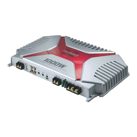
  9. Sony XM-1002HX User manual

Sony XM-1002HX User manual

Stereo Po] =r
Amplifier
Ell I II I
Operating Instructions
Mode d'emploi
Owner's Record
The model and sertal numbers are located on the bottom of the unit.
Record the serial number in the space provided below.
Refer tothese numbers whenever you call upon your Sony dealer tegardin 8this product.
Model No. XM-IOO2HX Serial No
XM- I OO2HX
SonyCorporaUon©1997 PnntedinI.$.A,
I I
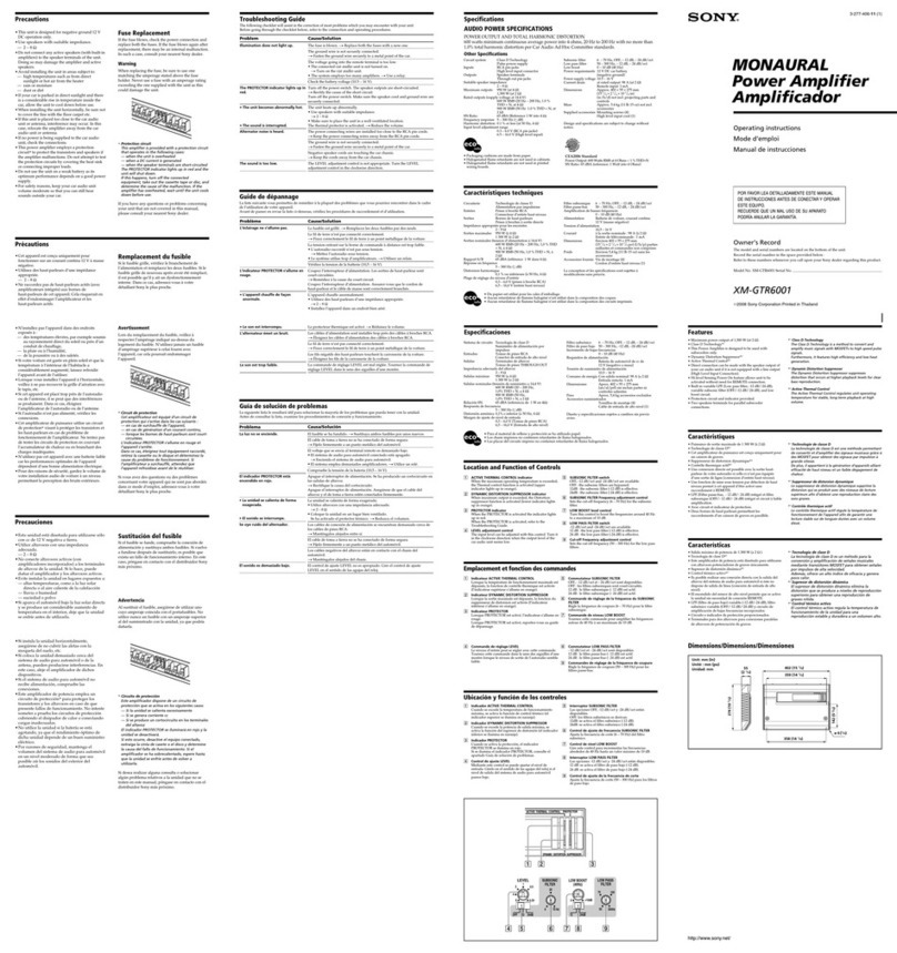
Precaution
•This unit is designed for negative ground 12 V
DCoperationonly.
• Use speakers with suitable impedance.
-- HI-CURRENTmode:1to2_.
-- HI-VOLTAGEmode:2to 4f_.
• Do not connect any active speakers (with built-in
amplifiers) to the speaker terminals of the unit.
Doingso may damagethe active speakers.
• Avoid installing the unit where:
-- it would be subject to high temperatures such
from direct sunlight or hot air from the
heater
-- it would be exposed to rain or moisture
-- it would be subject to dust or dirt.
•If your car is parked in direct sunlight and there
isa considerableriseintemperatureinsidethe
car,allowtheunittocooldown beforeuse.
•When installingtheunithorizontally,be surenot
tocoverthefinswiththefloorcarpetetc.
•Ifthisunitisplacedtooclosetothecarradio,
interferencemay occur.Inthiscase,relocatethe
amplifieraway from thecarradio.
•Ifno power isbeingsuppliedtothecassette
playerortuner,checktheconnections.
•Thispower amplifieremploys a protection
circuit*toprotectthetransistorsand speakersif
theamplifiermalfunctions.Do notattempttotest
theprotectioncircuitsby coveringtheheatsink
orconnectingimproperloads.
•Do notusetheuniton aweak batteryasits
optimum performancedepends on a goodpower
supply.
•Forsafetyreasons,keep your caraudiovolume
moderateso thatyou canstillhearsounds
outsideyour car.
Fuse Replacement
If the fuse blows, check the power comaection and
replace the fuse. If the fuse blows again after
replacement, there may be an internal malfunction.
In such a case, consult your nearest Sony dealer.
Warning
When replacing thefuse, be sureto useone
matching the amperage stated above the fuse
holder. Never use afuse with an amperage rating
exceeding the one supplied with the unit as this
could damage the unit.
*Protection circuit
Thisamplifieris provided with a protection circuit that
operatesin thefollowing cases:
-- whenthe unit is overheated
-- whena DC current isgenerated
-- whenthe speaker terminalsareshort circuited.
Thecolorofthe POWERIPROTECTOR indicator will
changefrom green to red,and theunit willshut down.
If this happens,turn off theconnected equipment, take out
thecassettetape or disc,and determine thecauseof the
malfimction.If the amplifierhas overheated,wait until the
unit coolsdown beforeuse.
If you have any questions or problems concerning
your unit that are not covered in this manual,
please consult your nearest Sony dealer.
Troubleshooting Guide
The following checklist wiLl assist in the correction of most problems which you may encounter with your
unit.
Before going through the checklist below, refer to the connection and operating procedures.
Problem Cause/Solution
The POWERIPROTECTOR The fuseisblown.--_Replacethefusewith a new one.
Indkator does not lightup. The ground leadisnot securelyconnected._Fastentheground lead
securely to a metal point ofthe Car.
The voltage going into the remote terminal is too low.
• The connected master unit is not turned on. _ Turn on the master unit.
•The system employs too many amplifiers. --_ Use a relay.
Check the battery voltage (10.5-16 V).
The OVER CURRENT indicatorlightup Turn oft the power switch.The speaker outputsareshort-circuited.---*
In amber. Rectify the causeof the short-circuit.
The OFFSET indicator lights up In Turn oft the power switd_. Make sure the speaker cord and ground lead
amber, are securely connected.
The THERMAL Indicatorlightsup In The unitheats up abnormally.
amber. •Use speakerswith suitableimpedance.
- HI-CURRENT mode: I to8_.
- HI-VOLTAGE mode: 2 to8 _.
Use HI-C_ENT mode toreduce generatedheat.
•Make sureto placethe unitina wellventilatedlocation.
Alternator noise Is heard. The power connecting leads are installed too close to the RCA pin cords.
---#Keep theleads away from the cords.
The ground leadisnot securelyconnected.--+Fastenthe ground lead
securelytoa metal point ofthecar.
Negative speakerleadsaretouchingthecar chassis._ Keep theleads
away from the carchassis.
The sound Is muffled. The FILTER selector switch is set to the "LPF" position•
The sound is too low. The LEVEL adjustment control is set to the "MIN" position.
III I I IIIIIIIII
Specifications
AUDIO POWER SPECIFICATIONS
POWER OUTPUT AND TOTAL HAI_vlONIC DISTOR'IION
100/50 watts per channel minimum continuous average power into
4 ohms, both channels driven from 20 Hz to 20 kHz with no more
than 0.04% total harmonic distortion per Car Audio Ad Hoc
Committee standards.
Other Specifications
Circuitsystem OTL (outputtransformerless)
circuit
Pulsepowersupply
Inputs RCA pin jacks
High level input connector
Outputs Speaker terminals
Through out pin jacks
Speaker impedance
I*- 8D (stereo)
2*-8t_(whenusedasabridging
amplifier)
Maximum outputs(HI-CURRENT/HI-VOLTAGE)
120/230W x 2(at4D)
380/580W (monaural)at4
Ratedoutputs(HI-CURRENT/HI-VOLTAGE)
(supplyvoltageat14.4V)
50/100W×2 (20Hz- 20kHz,
0.04%THD, at 4 11)
70/140 W×2(20Hz - 20 kHz, 0.1
%THD, at212)
140/280 W (monaural) (20 Hz - 20
kHz, 0.1% THD, at 4 t'l)
Frequencyresponse
5 Hz - 50kHz (Z'dB)
Harmonicdistortion
0.005%or less
(atlkHz, 4a)
Input level adjustment range
0.2- 4.0V (RCA pin jacks)
0.4- 8.0V (High level input)
High-pass filter 50 - 200 Hz, -12 dB/oct
Low-pass filter 50 - 200 Hz, -12 dB/oct
Low boost 0 - 10 dB (40 Hz)
Power requirements 12 V DC car battery
(negative ground)
Power supply voltage 10.5 - 16 V
Current drain at rated output: 26 A
(4t'1 HI-VOLTAGE mode)
,Remote input: 2 mA
Dimensions Approx. 258 x 50 x 320 mm
(101/4 x 2 x 12 s/s in.)
(1/h /p) not incl. projecting par ts
and controls
Mass Approx. 3.3 kg (7 Ib. 4 oz.) not
incL accessories
Supplied accessories Mounting screws (4),
Terminal cap (1)
Optionalaccessories Connectingcord for power
amplifier RC-46
Designand specificationsaresubjectto change
withoutnotice.
* HI-CURRENT only
Features
•Maximum power output of 230 watts per
channel (at 4£_).
•This unit can be used as a bridging amplifier
with a maximum output of 580 watts.
•Direct connection can be made with the speake_
output of your car audio if it is not equipped
with the line output (High level input
connection).
• Built in variable LPF (Low-pass filter), HPF
(High-pass filter) and low boost circuit.
• Dual mode connection possible for a multi-
speaker system.
•Possible to switch between HI-CURRENT mode
(1-2 _) and HI-VOLTAGE mode (2-4 £2).
•Protection circuit and indicator provided.
•Pulse power supply* for stable, regulated output
power.
• New circuit wilich _emoves the _ouit:_ zesistance
from the final MOS FET output stage, and drives
the speaker directly.
* Pulse power supply
This unit has abuilt-in power regulator which converts
the power supplied by the DC 12 V ear battery into high
speed pulses using a semiconductor switch. These pulses
are stepped up by the built-in pulse transformer and
separated into both positive and negative power supplies
before being converted into direct current again. This is to
regulate fluctuating voltage from the car battery. This
light weight pawer supply system provides ahighly
ef_cient power supply with alow impedance output.
I I I I IIIII IIII I
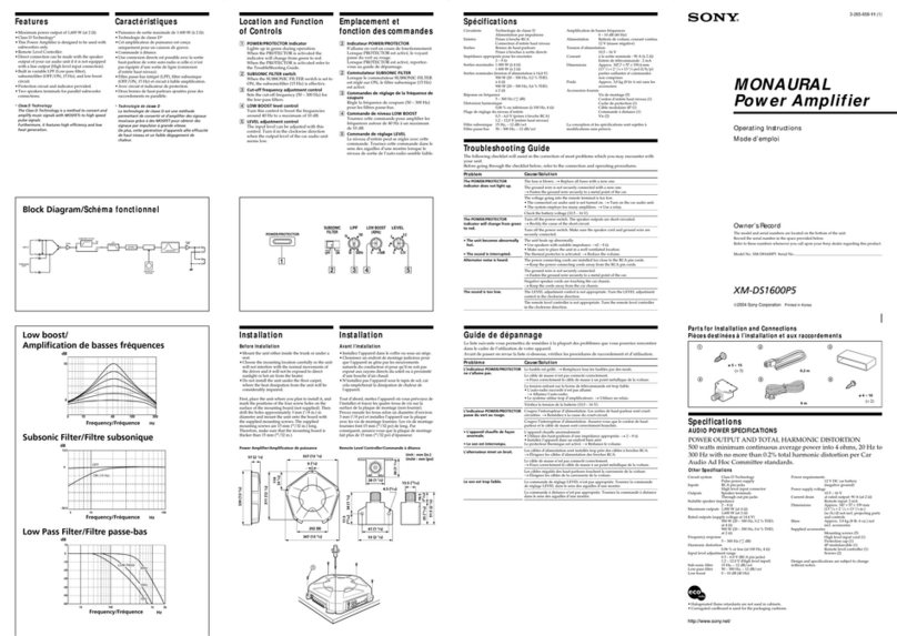
Location and Function of Controls
[] MODE indicator
IndicatesHI-CURRENT mode or HI-VOLTAGE mode.
[] POWER/PROTECTOR indicator
•OVER CURRENT lights up in green during normal operation, rl'he coiol will
change from green to amber when receiving a powerful signal.
• OFF SET lights up green during normal operation. The color will change
from green to amber when the voltage going out to the Speaker terminal or
the Pin Jack is too high.
• THERMAL lights up in green during normal operation. The color will
change from green to amber when the temperature rises to an unsafe level.
The color will return to green when the temperature returns to normal.
[] LEVEL adjustment control
The input level can be adjusted with this control when using source
equipment made by other manufacturers. Turn it to MAX when the output
level of the car audio seems low.
[] LOWBOOST level control
Turn this control to boost the frequencies around 40 Hz to a maximum of 10
dB.
[] Cut-off frequency adjustment control
Sets the cut-off frequency (50-200 Hz) for the low-pass or high-pass filters.
[] FILTER selector switch
When the switch is in the LPF position, the filter is set to low-pass. When in
the HPF position, the filter is set to high-pass.
[] HI-CURRENT/HI-VOLTAGE mode switch (located on the bottom of the unit)
Remove the bottom cover to access the switch.
•In HI-CURRENT mode the speaker impedance is 1 to 2 _. This
mode sends a signal via parallel circuits for a powerful sound
•In HI-VOLTAGE mode the speaker impedance is 2 to 4 ft. In this mode
you can enjoy clear sound with the dynamic range.
_.--Tr_ ODE .... _f POWER/PROTECTER I
Hla_URR ENT HbVOLTAQE ,J _OVER CUIR RE NT OFFS_ THERMAL J
FILTER
LEVEL LOWBOOST LPF OFF HPF
LOW BOOST
dB
l0
lO
Cut-off frequency/Fr6quence de coupure
dB
l0
0
40
-20
-3O
'4O
-5O
"6O
-70
"10
ill Iiii ii ii
/.....
"_'! '_
II II I
I I II I
II II
II il
I I II i I I II
'÷4 -- _-I-_ 4-4#
I I I I I II
I I II I II
-- -_.. - _--1- €.-+ 4 4
,_r iGI_I . i i i i i i ii
•I _,_-e0ogz--l---L- L-I-L1J"
I I I I i I II
',_,_ ........
II II I I I t I I II
,Ij.JJ ..... _ i I .i l,[. i.a
li I I I I I I I II
ill I I I I I I II
10
4 " _T ' [ ' , ,
I I I I I I I
I I I I I I I
.....,_ _,,._ r'.<.,,l_ _
................ SaH_-N,.:
I I I I I i li
.... 4--- d--I- l-I--I. &t .... -%-
I I I I I I I ~-_
I,,, 11 LI
I I I IIII
I I I 1 I t I
, , , , , ,,
I00 lk
40 100 lk
FREQUENCY Hz FREQUENCY Hz
Circuit Diagram /Sch6ma du circuit
Lch (_
(MONO)
FILTER
LEVEL _--° h
<ow0oo0,
I
I
Inverted
Rch(_) ''
FILTER
IMONO
,2
I
!
IPower
AMP %,
Connections
Caution
•Before making any connections, discolu_ect
the ground terminal of the car battery to avoid
short circuits.
* Be sure to use speakers with an adequate
power rating. If you use small capacity
speakers, they may be damaged.
• Do not connect the 0 terminal of the speaker
system to the car chassis, and do not connect
the 0 terminal of the right speaker with that
of the left speaker.
•Install the input and output cords away from
the power supply lead as running them close
together can generate some interference noise.
IThis unit is a high powered amplifer.
Therefore, it may not perform to its full
potential if used with the speaker cords
supplied with the car.
•If your car is equipped with a computer
system for navigation or some other purpose,
do not to remove the ground wire from the
car battery. If you disconnect the wire, the
computer memory may be erased. To avoid
short circuits when making connections,
disconnect the +12 V power supply lead until
all the other leads have been connected.
Make the terminal
connections as Illustrated below.
Note
When you tighten the screw, be careful not to
apply too much torque* as doing so may damage
the screw.
*The torque value should be less than 1N•m.
Pass the leads
through the cap,
connect the leads,
then cover the
terminals with the
cap.
.)
Power Connection Leads
C&bles d'alimentation
(
Remote output *|
Sortie de I
tdldcommande *
(REM OUT)
1_ IIII1_ to a metal point of the car
vers une pattie mC_tallique
de la carrosserie
O O
Car audio [_
Fuse (30 A)
Autoradio Fusible (30 A)
+12 V car battery
Batterle de volture +12 V
*If you have the factory original or some other car audio without aremote output on the amplifier, connect the remote input
terminal (REMOTE) to the accessory power supply.
*Si vous disposez du moddle d'origine ou d'un autre autoradio dont l'amplificateur ne comporte pas de sortie de
t_qdcommande, raccordez la borne d'entr_e de tdl_commande (REMOTE) _la prise d'alimentation aecessoires.
Notes on the power supply
•Connect the +12 V power supply lead only after all the
other leads have been connected.
•Be sure to connect the ground lead of the unit
securely to a metal polnt of the car. A loose
connection may cause a malfunction of the
amplifier.
•Be sure to connect the remote control lead of the car audio
to the remote terminal.
•When using a car audio without a remote output on the
amplifier, connect the remote input terminal (REMOTE)
to the accessory power supply.
•Use the power supply lead with afuse attached (30 A).
•Place the fuse in the power supply lead as close as possible
to the car battery.
•Make sure that the leads to be connected to the +12 Vand
GND terminals of this unit respectively must be larger
than lO-Gauge (AWG- IO) or "with the sectional area of
mare than 5mmL
•When using the optional RC-46 power amplifier
connecting cord, consult that manual for proper use.
2-Speaker System
Syst_me & 2 haut-parleurs
ICar audio I
Autoradio
Left speaker Right speaker
(min. 1_/2Q)* _ _ (min. 1_/2L'1)*
Haut-parleur Haut-parleur
gauche d roit
(rain. 1_/2Q)* l* HI-CURRENT/HI-VOLTAGE modeI (mln. 1_/2Q)** mode HI-CURRENT/HI-VOLTAGE
For details on the settings of switches and controls,
refer to "Location and Function of Controls."
Pour plus de ddtails sur les rdglages des commutateurs et
eommandes, reportez-vous _ "Emplacement et_nction
des commandes".
As a Monaural Amplifier
Comme amplificateur monaural
i Car audio I
Autoradio
LINE OUT
Left channel _Right channel
Canal gauche _Canal droit
Left speaker ?
(min. 2_/4_Q)* _
Haut-parleur
gauche
(mln. 20/4_)* I* HI-CURRENT/HI-VOLTAGE mode ! Right speaker (mln. 2_/4_)*
I• mode HI-CURRENT/H!-VOLTAGE ] Haut-parleur droit (min. 2_/4_)*
For details on the settings of switches and controls,
refer to "Location and Function of Controis."
Note
Make sure that the line output from the car audio is
connected to the jack marked "L (MONO)" on the
unit.
Pour plus de ddtails sur les rdglages des commutateurs
et commandes, reportez.vous _"Emplacement et
fenction des commande: ".
Remarque
V_rifiez que la sortie de ligne de l'autoradio est
raccordde _la prise portant l'indicatlon "L (MONO)"
sur l"appareil.
As the Monaural Amplifier for a Subwoofer
Comme amplificateur monaural pour un haut-parleur
d'extr_mes graves
ICar audio
Autoradio
LINE OUT
Subwoofer (rain. 2_/4_)*
Subwoofer (mln. 2_/4_)*
For details on the settings of switches and controls,
refer to "Location and Function of Controls."
Note
If you wish to use a subwoofer as a monaural speaker,
connect the speaker as illustrated above. The output
signals to the subwoofer will be the combination of the
both right and left output signals.
* HI-CURRENT/HI-VOLTAGE mode
• mode HI-CURRENT/HI-VOLTAGE
Pour plus de ddtails sur les rdglages des commutateurs
et commandes, reportez-vous _"Emplacement et
fonction des commandes".
Remarque
Si vous d_sirez utiliser un haut-parleur d"extr_mes
graves comme haut-parleur monaural, raccordez ls
haut-parleur comme illustrd ci-dessus. Les signaux de
sortie vers le haut-parleur d' extr_mes graves seront une
combinaison des signaux de sortie droit et gauche.
2-way System
Syst_me 2 voies
Two output channels
Duex canaux de sortie
Full range
speakers
(mln. 1_2/2Q)*
Haut-parleurs h
large bande
(rain. 1_/2_)*
Car audio I
Autoradio
EOUT
d h
•IIII _-_
O@€_O OOOO
* HI-CURRENT/HI-VOLTAGE mode 1• mode HI-CURRENT/HI-VOLTAGE
Use the THROUGH OUT terminal when
you install more amplifiers. The signals are
output as they were input. (LOW BOOST,
HPF, LPF do not work.)
Notes
•A maximum 3 amplifiers can be connected to the
THROUGH OUT terminal. If you connect more
than three ampli_ers, it may cause problems such as
sound dropout.
•High level input connection cannot use THROUGH
OUT.
Utilisez la borne THROUGH OUT lorsque
vous installez plusieurs amplificateurs. Les
signaux sont sortis comme ils sont entr4s.
(LOW BOOST, HPF, LPF ne fonctionnent
pas.)
Remarques
•Vous pouvez raccorder un maximum de3
ampliJicateurs _la borne THROUGH OUT. Si vous
raccordez plus de trois amplificateurs, cela peut
provoquer des probl_mes comme des baisses du son.
•Avec une connexion d'entrde de haul niveau, vous ne
pouvez pas utiliser THROUGH OUT.
Four output channels
Quatre canaux de sortie
Ca r audio
Autoradio
Full range
speakers
(mln. 1_/2_z) •
Haut-parleurs
/i large bande
(min. 1_/2_) •
_/_ _E OUT
0€O0 OO00
Subwoofers
(mln. 1G_/2_)* [_
For details on the settings of switches and controls,
refer to "Location and Function of Controls."
Note
In this system, the volume of the subwoofers will be
controlled by the car audio fader control.
* HI-CURRENT/HI-VOLTAGE mode I
* mode HI-CURRENT/HI-VOLTAGE ]
Pour plus de d_tails sur ies r_glages des commutateurs
et commandes, reporte'z-vous _ "Emplacement et
fonction des commandes'.
Remarque
Dans ce syst_me, le volume des haut-parleurs
d"extr_nes graves est contralti par la commande de
balance avant/arridre de l'autoradio.
Dual Mode System (With a Bridged Subwoofer)
Double mode de connexion (avec un haut-parleur
d'extr_mes graves en pont)
Car audio T_
Autoradlo
L LINE OU
C2
Left speaker Right speaker
Haut-parleur gauche Haut-parleur drolt
Table of crossover values for
6 dB/0ctave (4 ohms)
Subwoofer
Subwoofer
Tableau des valeurs de recoupement
pour 6dB/octave (4 ohms)
Crossover LC 1 /C2 Fr6quence de L C1 /C2
Frequency (coil)* (capacitor)* recoupement (bobine)* (condensa-
unit: Hz unit: mH unit: _F unit_: Hz unit_:mH teur)* unit4:/_F
50 12.7 800 50 12,7 800
80 8.2 500 80 8,2 500
100 6.2 400 100 6,2 400
130 4.7 300 130 4,7 300
150 4.2 270 150 4,2 270
200 3.3 200 200 3,3 200
260 2.4 150 260 2,4 150
400 1.6 100 400 1,6 100
600 1.0 68 600 1,0 68
800 0.8 50 800 0,8 50
1000 0.6 39 1000 0,6 39
*(not supplied) *(non fournis)
Notes
•When using passive crossover networks in a multi-speaker
system, care must be taken as the speaker system's
;impedance should not be lower than that of the suitable
;impedancefor this unit.
•When you are installing a 12 decibels/octave system in
your car, the following points must be considered. In a 12
decibels/octave system where both a choke and capacitor
are used in series to form a circuit, agreat care must be
taken when they are connected. In such a circuit, there is
going to be an increase in the current which by-passes the
speaker with frequencies at around the crossover
frequency. If audio signals are continued to befed into the
crossover frequency area, it may cause the amplifier to
become abnormally hot or the fuse will be blown. Also if
the speaker is disconnected, a series-resonant circuit will
be formed by the choke and the capacitor. In this case, the
impedance in the resonance area will decrease
dramatically resulting in a short circuit like situation
causing a damage to the ampli_er. Therefore, make sure
that aspeaker is connected to such a circuit at all times.
High Level Input Connection
(As aMonaural Amplifier for a Subwoofer)
Connexion d'entr_e il haut niveau
(Comme ampllficateur monaural pour un haut-parleur d'extr_mes
graves)
Left speaker
Haut-parleur gauche
Right speaker
Haut-parleur drolt
Car audio I
Autoradio
Input cord (Not supplied)
Cable d'entMe (Non fournls)
I I
O
Subwoofer (min. 2_/4_)* •mode HI-CURRENT/HI-VOLTAGE
For details on the settings of switches and controls,
refer to "Location and Function of Controls."
Note
If you wish to use asubwoofer as a monaural speaker,
connect the speaker as illustrated above. The output
signals to the subwoofer will be the combination of both
the right and left output signals.
High Level Input Connection (2-SpeakerSystem)
Connexion d'entr_e &haut niveau
(Syst_me tt 2 haut-parleurs)
Input cord (Not supplied)
C&ble d'entr_e (Non
foumls)
White O Left speaker output
Blanc _mbm_O_D"_rtle[ I haut-parleur gauche
""1 Car audio
Black-striped cord O /_ Autoradlo
Cordon ra_ _!__Rlght I
Gray mb speaker output
Grls Sortie haut-padeur drolt
Black-striped cord
Cordon ray_ now
I
IIII
O@€O
Left speaker _ _ Right speaker
(mln. 1_/2Q)* _ _ (mln. 1_/2_'1) •
Haut-parleur Haut-parleur
gauche I HI-CURRENT/HI-VOLTAGE mode _I droit
(mln. 1_/2_)* : mode HI-CURRENT/HI-VOLTAGE I (mln. 1_/2_)*
For details on the settings of switches and controls,
refer to "Location and Function of Controls. "
Pour plus de ddtails sur les r_glages des commutateurs
et commandes, reportez-vous _ "Emplacement et
fenction des commandes". i
High Level Input Connection (Asa Monaural Amplifier)
Connexion d'entrde &haut niveau
(Comme amplificateur monaural)
Black-stripedcord Left speaker output Right speaker output
Cordon ray_ nolr Sortie haut-parleur gauche Sortie haut-parleur
drolt
Caraudio
Autoradio
Input cord (Not supplied)
Clible d'entr6e (Non fou rnls)
Black-striped cord
Cordon ray_ nolr
0€0 •
Left speaker yRight speaker U
Haut-parleur Haut-parleur drolt
gauche (min. 2Q/4Q)*
(rain. 2_/4_)* I* HI-CURRENT/HI-VOLTAGE mode I
• mode HI-CURRENT/HI-VOLTAGE I
I
For details on the settings of switches and controls,
refer to "Location and Function of Controls."
Note
Make sure that the line output from the car audio is
connected to the jack marked "L (MONO)" on the
unit.
Pour plus de dgtails sur les rdglages des commutateurs
et commandes, reportez-vou_ _ "Emplacement et
fonction des commandes'.
Remarque
V_ri_ez que la sortie de ligne de l'autoradio est raccordde
la prise portant l'indicatlon "L (MONO)" sur
l'appareil.
Speaker cord direct in connector
Cordon de haut-parleur directement dens le connecteur
.1
*2
White F
Blan_
Left speaker
Haut-padeur gauche I Car audio
Right speaker Ii Autoradlo
Haut-padeur droit
G_.ray Black-stripedcord
Gds Cordon ray_ nolr
f
"1
Left speaker
Haut-parleur gauche I
Car audio
Autoradlo
Right speaker
I Haut-parleur drolt
Black/Gray
Nolr/Gris ___
Gray
Gds
_,_ Cord diameter 0.3 - 1.25 mm (AWG 22 - 16)
J_Section du cordon : 0,3 -1,25 mm (AWG 22-16)
Flat-head screwdriver
Tournevls ,_lame plate _.___.__ 11 (_hi)
Unit :mm (in.)
Unit_ : mm (po.)
i
i
Other manuals for XM-1002HX

4

Other Sony Amplifier manuals

Sony XM-3040F User manual

Sony

Sony XM-3040F User manual

Sony XM-GS6DSP User manual

Sony

Sony XM-GS6DSP User manual

Sony XM-SD51X - Currently Not Available User manual

Sony

Sony XM-SD51X - Currently Not Available User manual

Sony TAD-M30 User manual

Sony

Sony TAD-M30 User manual

Sony WM-EX368 User manual

Sony

Sony WM-EX368 User manual

Sony STR-K890 User manual

Sony

Sony STR-K890 User manual

Sony XM-GTX6020 User manual

Sony

Sony XM-GTX6020 User manual

Sony TA-VA80ES User manual

Sony

Sony TA-VA80ES User manual

Sony XM-405EQX Marketing Specifications User manual

Sony

Sony XM-405EQX Marketing Specifications User manual

Sony XM-502Z - Stereo Power Amplifier User manual

Sony

Sony XM-502Z - Stereo Power Amplifier User manual

Sony TA-3650 Setup guide

Sony

Sony TA-3650 Setup guide

Sony WAHT-SA10 - Wireless Audio Delivery System User manual

Sony

Sony WAHT-SA10 - Wireless Audio Delivery System User manual

Sony TA-A200 User manual

Sony

Sony TA-A200 User manual

Sony XM-S400D User manual

Sony

Sony XM-S400D User manual

Sony XM-280GTX Marketing Specifications User manual

Sony

Sony XM-280GTX Marketing Specifications User manual

Sony XM-222W User manual

Sony

Sony XM-222W User manual

Sony EA-80 User manual

Sony

Sony EA-80 User manual

Sony XDP-4000X Operating Instructions  (primary... User manual

Sony

Sony XDP-4000X Operating Instructions (primary... User manual

Sony TA-FE710R User manual

Sony

Sony TA-FE710R User manual

Sony XM-N1004 User manual

Sony

Sony XM-N1004 User manual

Sony XM-6ES User manual

Sony

Sony XM-6ES User manual

Sony TA-FE310R User manual

Sony

Sony TA-FE310R User manual

Sony XM-SD14X User manual

Sony

Sony XM-SD14X User manual

Sony TA-DA9000ES Quick start guide

Sony

Sony TA-DA9000ES Quick start guide

Popular Amplifier manuals by other brands

Yamaha M-70 owner's manual

Yamaha

Yamaha M-70 owner's manual

ELECTROCOMPANIET AW-250 owner's manual

ELECTROCOMPANIET

ELECTROCOMPANIET AW-250 owner's manual

Bastl Instruments Quattro Figaro manual

Bastl Instruments

Bastl Instruments Quattro Figaro manual

GE BA-7A manual

GE

GE BA-7A manual

Anedio A1 operating manual

Anedio

Anedio A1 operating manual

Perreaux 6160/P owner's manual

Perreaux

Perreaux 6160/P owner's manual

ATX SignalOn Series Installation & operation manual

ATX

ATX SignalOn Series Installation & operation manual

Unika GX-Series User instructions

Unika

Unika GX-Series User instructions

Henriksen Jazzamp 310 owner's manual

Henriksen

Henriksen Jazzamp 310 owner's manual

Aiken Amplification Intruder user manual

Aiken Amplification

Aiken Amplification Intruder user manual

FSR DV-HDA-12 user manual

FSR

FSR DV-HDA-12 user manual

Farenheit CLX260-2 owner's manual

Farenheit

Farenheit CLX260-2 owner's manual

RCF ES3323 quick guide

RCF

RCF ES3323 quick guide

Martin Roland MA-3000HD Operation manual

Martin Roland

Martin Roland MA-3000HD Operation manual

Audio 2000 AKJ7403 owner's manual

Audio 2000

Audio 2000 AKJ7403 owner's manual

Xtant xtant1.1i Specification sheet

Xtant

Xtant xtant1.1i Specification sheet

Laney GS212IE operating instructions

Laney

Laney GS212IE operating instructions

DS18 NXL-X owner's manual

DS18

DS18 NXL-X owner's manual

manuals.online logo
manuals.online logoBrands
  • About & Mission
  • Contact us
  • Privacy Policy
  • Terms and Conditions

Copyright 2025 Manuals.Online. All Rights Reserved.