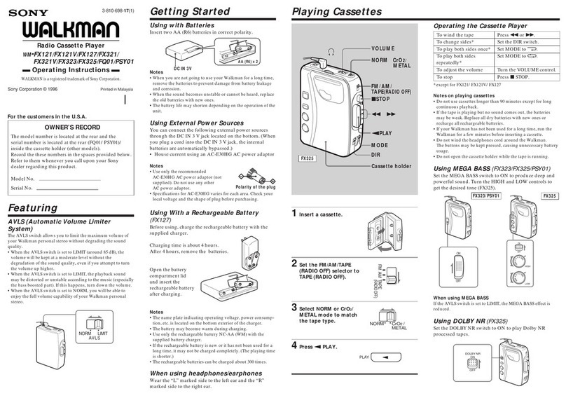
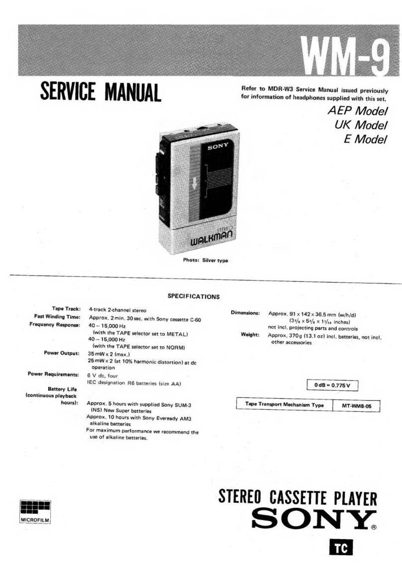
Sony WM-DD User manual

SPECIFICATIONS
Power
Requirements:
3
V
dc
Internal
batteries:
IEC
designation
R6
(size
A
A)
x
2
AC
power
adaptor:
Refer
to
the
following
chart
to
choose
the
correct
adaptor
for
your
area.
Country
Ac
power
line
voltage
Optional
ac
power
adaptor
US
Canadian
120
Vac,
60
Hz
AC-39
available
in
the
U.S.A.
and
Canada
UK
240
Vac,
50
Hz
AC-37
available
in
the
United
Kingdom
AEP
220
V
ac,
50
Hz
AC-37
available
in
European
countries
E
120
Vac,
(110,220
or
240
V
ac,
adjustable
by
Sony
personnel),
50/60
Hz
110,120,
220
or
240
V
ac,
adjustable,
50/60
Hz
AC-38
available
in
Japan
AC-38
available
in
other
countries
12
V
car
battery:
Sony
DCC-127A*
car
battery
cord
*For
connection
with
the
DCC-127A,
the
optional
PC-
200
dc
plug
adaptor
is
required.
Battery
Life
(continuous
playback
hours):
Approx.
9
hours
with
supplied
Sony
Eveready
AM3
alkaline
batteries
For
maximum
performance
we
recommend
the
use
of
alkaline
bat¬
teries.
Dimensions:
Approx.
79
x
109.2
x
29
mm
(w/h/d)
(3i/s
x4s/
16
x
13/ie
inches)
not
incl.
projecting
parts
and
controls
Weight:
Approx.
290g
(IO
1
/4
oz)
incl.
batteries,
not
inch
other
accessories
MICROFILM
Tape
Track:
Fast
Winding
Time:
Frequency
Response:
Wow
and
Flutter:
Power
output:
Output:
4-track
2-channel
stereo
Approx.
2min.
with
Sony
Cassette
C-60
40
—
15,000
Hz
(with
the
TAPE
selector
+
tn
METAL*
set
t0
CrOj
1
40
—
12,000
Hz
(with
the
TAPE
selector
set
to
NORM)
±0.13%
(DIN)
0.08%
WRMS
(NAB)
25
mWx
2
(max.)
20
mW
x
2
(at
10%
harmonic
distortion)
at
dc
operation
Headphone
jacks
(stereo
minijack)
...
2
load
impedance
8
—
300
ohms
Tape
Transport
Mechanism
Type
MT-WMDD-24
SERVICE
MANUAL

WM-DD
PARTS
IDENTIFICATION
O
VOLUME
control
0
HEADPHONES
jacks
(stereo
minijacks)
©
►
►
REW
(rewind)
button
0^4
FF
(fast
forward)
button
0<4
PLAY
(playback)
button
0
Lock
button
(to
secure
the
cassette
panel)
0
DC
IN
3
V
(external
power
input)
jack
©
BATTERY
indicator
©
■
STOP
button
0
TAPE
selector
0
Battery
compartment
(inside)
©
Cassette
panel
FEATURE
•
Capable
of
selecting
NORM
or
position
by
type
of
tape
in
use.
•
DD
(Disc
Drive)
system
that
has
superior
anti-roll¬
ing
effect
and
low
wow
and
flutter
has
been
em¬
ployed.
•
Auto
shut-
off
mechanism
in
FWD
mode
and
auto
off
mechanism
in
FF,
REW
modes.
i
■
t
2

Chip
components
Chip
components
include
resistors,
capacitors,
transistors,
diodes,
coil
and
adjustable
resistors.
In
this
section,
the
types
of
resistors,
ceramic
capacitors,
transistors
and
diodes
which
are
used
most
frequently
will
be
described.
Dimension
of
transistors
and
capacitors
Type
L
W
T
3216
3.2
1.6
0.45
~
0.6
2125
2.0
1.25
0.35-0.5
Identification
electrode
ceramic
base
side
(white
color)
electrodes
Resistor
Laminated
Ceramic
Capacitor
Transistor
Diode

Replacing
chip
components
All
chip
components
should
be
connected
and
disconnect¬
ed,
using
a
tapered
soldering
iron
[temperature
of
the
iron
tip:
less
than
280°C
(536°F)],
a
pair
of
tweezers
and
braid¬
ed
wire.
Precautions
for
replacement
1.
Do
not
disconnect
the
chip
component
forcefully.
Otherwise,
the
pattern
may
peel
off.
2.
Never
re-use
a
disconnected
chip
component.
Dispose
of
all
old
chip
components.
3.
To
protect
the
chip
component,
heating
time
for
attach¬
ing
the
component
should
be
within
3
seconds.
o
Removing
chip
components
(1)
R
emoving
solder
at
electrode
Remove
the
solder
at
the
electrode,
using
a
thin
braided
wire.
Do
not
remove
the
solder
of
the
part
(chip
component)
attached
adjacent
to
the
electrode.
(2)
D
i
sconnecting
chip
components
Turn
the
tweezers
with
the
soldering
iron
alternately
applied
to
both
electrodes,
and
the
chip
component
will
be
disconnected.
Take
careful
precautions
while
disconnecting,
because
if
the
chip
component
is
force¬
fully
removed
the
land
may
peel
off.
Never
re-use
a
disconnected
chip
component.
/
Turn
(3)
S
moothing
the
soldered
surface
After
disconnecting
the
chip
component,
remove
the
solder
by
using
a
braided
wire
to
smooth
the
land
surface.
o
Connecting
chip
components
The
value
of
chip
components
is
not
displayed
on
the
main
body.
Take
due
precautions
to
avoid
mixing
new
chip
components
with
other
ones.
(1)
A
pplying
solder
to
land
on
one
side
Apply
a
thin
layer
of
solder
to
the
land
on
one
side
where
the
chip
component
is
to
be
connected.
Too
much
solder
may
cause
bridging.
Small
quantity
of
solder
(2)
S
peedy
soldering
Hold
the
chip
component
at
the
desired
position,
using
tweezers,
and
apply
the
soldering
iron
in
the
arrow-marked
direction.
To
protect
the
chip
compo¬
nent,
heating
time
should
be
within
3
seconds.
Land
prin
ted
circui
t
board
(3)
S
p
eedy
soldering
of
electrode
on
the
other
side
Solder
the
electrode
on
the
other
side
in
the
same
way
as
in
(2)
above.


WM-DD
2-1.
FWD
mode
SECTION
2
MECHANICAL
OPERATION
head
chassis

WM-DD


WM-DD
WM-DD
1.
Motor
section
installation
0
Tighten
loosely
@
Tighten
firmly
Wow
&
flutter
and
motor
position
1.
Adjust
with
the
thrust
screw
so
that
rotor
thrust
play
is
within
0.1
mm.
(When
confirming
play,
press
motor
down
so
that
the
motor
pulley
and
rotor
rubber
section
do
not
touch.)
2.
Adjust
with
the
adjustment
screw
so
that
con¬
sumed
current
satisfies
the
value
below
in
FWD
mode.
Consumed
current:
Approx.
5
mA
higher
current
than
mini¬
mum
point,
in
tightening
direction.
Note:
If
the
adjustment
screw
is
loosened
too
much,
adjustment
will
be
impossible.
Perform
adjustment
within
5
turns
from
the
tightened
state.
3.
Confirm
that
the
wow
meter
value
is
0.08%W*
RMS.
Conditions:
—
FWD
state
—
power
supply
voltage:
2.5
V
-tape:
WS-48
(3
kHz,
0
dB)
Use
portion
near
the
end.
4.
At
2
V
power
supply
voltage,
confirm
normal
FWD
operation.
5.
When
@
and
@
are
not
satisfied,
repeat
ad¬
justment
again
starting
with
“Motor
Section
Installation”.
O
Tighten
screw
loosely.
©
Tighten
screw
while
pressing
the
motor
section
lightly
in
in
the
direction
of
the
arrow.
©
Tighten
the
screw.
Press
down
adjustment
screw
adjustment
screw
4-2.
ELECTRICAL
ADJUSTMENTS
Head
Height
Adjustment
1.
Prepare
an
adjustment
cassette
as
shown
below.
C-120
tape
cassette
portions.
2.
In
playback
mode
and
viewing
from
the
front,
adjust
the
head
heights
to
eliminate
tape
curl
and
tape
twist
at
portions
shown
by
the
arrow.
~8
rCZT
m.
—
7
1
tape
guide
U
playback
head
—n
3r
3-578-138-01
(t=
0.1)
3-578-138-11
ft
=0.2)
Shim,
head
height
adjustment
3.
If
necessary,
adjust
the
height
of
the
tape-guide
by
turning
the
adjustment
screw.
adjustment
screw
4.
Apply
locking
compound
on
adjustment
screw.
Playback
Head
Azimuth
Adjustment
Procedure:
1.
Mode:
playback
test
tape
P-4-A81
(6.3kHz,-10dB)
HEADPHONES
2.
Turn
the
adjustment
screw
for
the
maximum
output
levels.
If
these
levels
do
not
match,
turn
the
adjustment
screw
until
both
of
output
levels
match
together
within
0.5
dB.
output
levels
within
J
0.5
dB^
Screw
^
■
—
position
3.
Phase
Check
Mode:
playback
test
P-4-A81
(6.3
kHz,
-10dB)
L-CH
R-CH
peak
peak
33
£2
oscilloscope
HEADPHONES
Screen
pattern
0@©
®Q
(
i
n
phase
45°
90°
f
13
5°
180°,
good
wrong
Adjustment
Location:
12

SECTION
3
DISASSEMBLY
Note:
Follow
the
disassembly
procedure
in
the
numerical
order
given.
CONTROL
PANEL
CASSETTE
PANEL
(Compression
coil
Installation)
Control
panel
can
be
removed
together
with
cassette
panel.
screw
O
precision
screw
P
1.4x3.5,
TYPE
1
©
precision
screw
P
1.4
x
2.5,
TYPE
1
screw
©
Depress
the
FF
and
REWbuttons.
control
panel
AUDIO
BOARD
HOLDER
©
precision
screw
P
1.4x3
5
(TYPE
3)
Turn
the
holder
a
half
turn
in
the
direction
shown
by
the
arrow,
and
remove
the
holder
taking
care
to
protruding
parts.
(With
main
board
removed)
Be
careful
not
to
lose.
©
precision
screw
P
1.4x2,
TYPE
1
Mechanism
section
Main
Board
Be
careful
not
to
lose.
protruding
part
protruding
part
©
wire
holder
0
wire
holder
©
Raise
up
the
circuit
board
taking
care
not
to
break
the
lead
wires.
A
precision
screw
P
1.4x2,
TYPE
1
holder
Pinch
roller
and
head
can
be
replaced.
Mechanism
section
can
be
checked.
SECTION
4
ADJUSTMENTS
PRECAUTION
1.
Clean
the
following
parts
with
a
denatured-
alcohol-moistened
swab:
playback
head
pinch
roller
capstan
rubber
belts
2.
Demagnetize
the
playback
head
with
a
head
demagnetizer.
3.
Do
not
use
a
magnetized
screwdriver
for
the
adjustments.
4.
After
the
adjustments,
apply
suitable
locking
compound
to
the
parts
adjusted.
5.
The
adjustments
should
be
performed
with
the
rated
power
supply
voltage
unless
otherwise
noted.

WM-DD
Channel
Level
Adjustment
Tape
Speed
Adjustment
Setting
Setting:
VOLUME
control:
mechanical
mid
VOLUME
control:
mechanical
mid
Procedure
Procedure
Made:
playback
Mode:
playback
speed
checker
LFM-30
or
digital
frequency
counter
test
tape
P-4L82
(333
Hz,
-10
dB)
VTVM
test
tape
WS-48
(3
kHz,
OdB)
HEADPHONES
Specification:
Level
difference
between
channels
less
than
2.5
dB
HEADPHONES
Specification:
1)
If
necessary,
connect
the
patterns
for
lower
level
channel.
2)
Confirm
that
the
output
level
of
HEAD¬
PHONES
is
fixed
when
repeating
playback
and
stop.
Adjustment
Location:
Adjustment
Location
RV602
C20!
0.0018
<HH>
Adjustment
Hole
control
pane!
Use
a
plastic
blade
screw
driver.
Speed
checker
Digital
frequency
counter
±2%
2,940
~
3,060
Hz
■
1
i
i
1
set
FT
di
13
WM-DD
•
Only
former
models
can
be
adjusted.
Wow
and
flutter
Adjustment
*Refer
to
wow
and
flutter
adjustment
on
page
11.
Setting:
Power
supply
voltage:
2
V
Tape:
Adjust
by
using
center
portion
of
tape.
Procedure:
playback
mode
test
tape
WS-48
(3kHz,
OdB)
Muting
Level
Adjustment
•
Replacing
IC301,
perform
this
adjustment
Setting:
Power
supply
voltage:
1.97
V
dc
Procedure:
oscilloscope
(Range:
DC,
Y-axis:
0.5
cm,
X-axis:
0.2
ms
/cm)
Make
sure
that
the
signal
is
obtained
at
head¬
phones
terminal.
FWD
button:
ON
P-4-L81
(333Hz,
OdB)
VTVM
Connect
the
oscilloscope
to
pins
(4)
and
(?)
ofIC601.
Adjust
RV602
for
the
specified
waveform
on
oscilloscope
as
shown
below.
Set
peak
point
of
waveform
to
0.7
—
1
V.
HEADPHONES
If
necessary,
bridge
the
pattern
Adjustment
Location:
variation
R302
I
R303
I
R30II
220
f
130
§
1.5k
,
(I/8W)
T(|/8W)T(I/8W)'
Adjustment
Location:
oscilloscope
(Range:
DC,
Y-axis:
0.5
cm,
X-axis:
0.2
ms/cm)
IC601
RV602
RV602
peak
point
of
waveform
clockwise
®
I
counterclockwise
®
14

SECTION
5
DIAGRAMS
B
WM-DD
WM-DD
H
5-1.
MOUNTING
DIAGRAM
•
Semiconductor
Lead
Layouts
2SA1013
CX887
CX891
1S5150
SR506D
cathode
2SK246
G
D
2SC1623
2SK184
2SD1012
2SA1162
1SSI
23
m
Color
code
of
sleeving
over
the
end
of
the
jacket.
:
parts
extracted
from
the
component
side.
:
parts
extracted
from
the
conductor
side.
►
hi
:
signal
path
:
L-CH
signal
path
:
R-CH
signal
path
Q
503
IC60I
60|
1C
604
603
501
502
605
606
602
IC30I
D
602
603
601
15
-
—n
J30l
_
l
kAU
j
H
E
ADPHONES/A|
II
IheadphonesTb]
METAL
unntl
Cr02
N0RM
S30I
fTAPEl
16

SECTION
6
EXPLODED
VIEWS
AND
PARTS
LIST

WM-DD
WM-DD
B
H
5-2.
SCHEMATIC
DIAGRAM
Ref.
No.
FORMER
NEW
C604
0.01
0.047
C605
lOOp
330p
R607
62k(l/8W)
47
k(1/8
W)
R6I2
150
.
33
R6I3
IMI/8W)
330
(1/8
W)
RV602
2.2
k
—
B
R6I0
Ik
Q602
2SK246-Y
2SKI84GR
2SKI86C
D603
ISSI23
Note:
•
All
capacitors
are
in
/if
unless
otherwise
noted.
pF
:
jjliiF
50WV
or
less
are
not
indicated
except
for
electrolytics
and
tantalums.
•
All
resistors
are
in
ohms,
Vio
W
unless
otherwise
noted.
ka
:
1000
a,
Mft
:
1000ka
:
panel
designation.
U
:
adjustment
for
repair.
—
--:
B-
bus.
Voltages
are
dc
with
respect
to
ground
unless
otherwise
noted.
Readings
are
taken
under
no-signal
conditions
with
a
VOM
(20
ka/v).
Voltage
variations
may
be
noted
due
to
normal
produc¬
tion
tolerances.
Total
current
is
measured
with
no
cassette
installed.
DRY
BATTERY
-±-
SIZE
"AA"
(IEC
DESIGNATION
R6)
2PCS.3V
CAUTION
THIS
UNIT
MAY
BE
SHUT
OFF
BY
TOUCHING
THIS
POINT
WITH
VOM
PROBE.
18

GENERAL
SECTION
ACCESSORY
&
PACKING
MATERIAL
No.
Part
No.
Description
No.
Part
No.
Description
1
3-307-831-00
SCREW,
PANEL
51
3-310-946-00
CASE,
CARRYING
2
3-307-833-00
BUTTON,
LOCK
52
3-310-953-00
INDIVIDUAL
CARTON
3
3-310-906-00
LABEL,
MODEL
NUMBER
53
3-310-956-00
CUSHION
(UPPER)
4
3-310-908-00
KNOB,
INDICATION,
CONTROL
54
3-310-957-00
CUSHION
(LOWER)
5
3-310-909-00
KNOB,
ORNAMENTAL,
CONTROL
55
3-310-961-00
FRAME,
INNER
6
3-310-947-00
SPRING,
COMPRESSION
56
3-701-308-00
(BLACK)_LABEL,
PRODUCT
COLOR
7
3-545-657-11
(FOR
BLACK)..
...BUSH
57
3-701-309-00
(SILVER)...LABEL,
PRODUCT
COLOR
7
3-545-657-21
(FOR
GOLD,
SILVER,BLUE,
GREEN).
...BUSH
58
3-701-311-00
(RED).LABEL,
PRODUCT
COLOR
7
3-545-657-41
(FOR
RED).
...BUSH
59
3-701-314-00
(BLUE).LABEL,
PRODUCT
COLOR
8
3-578-101-00
PLATE,
ORNAMENTAL
60
3-701-317-00
(GOLD).LABEL,
PRODUCT
COLOR
9
3-578-109-00
CONTACT
61
3-701-320-00
(GREEN)....LABEL,
COLLOR
10
3-578-114-00
PANEL,
CHASSIS
62
3-701-625-00
BAG,
POLYETHYLENE
11
3-578-115-00
LID,
BATTERY
CASE
63
3-701-999-00
LABEL,
SERIAL
NUMBER
12
3-578-232-00
(FOR
GOLD,
SILVER,BLUE,
GREEN).
...ORNAMENT,
64
3-773-236-11
MANUAL,
INSTRUCTION
ADJUSTMENT
HOLE
65
3-795-510-11
CARD,
WARRANTY,
INTERNATIONAL
12
3-578-232-11
(RED).ORNAMENT,
ADJUSTMENT
HOLE
12
3-578-232-21
(BLACK)...ORNAMENT,
ADJUSTMENT
HOLE
66
8-893-535-00
TAPE,
DEMONSTRATION
(CD-817)
67
8-951-183-90
MDR-W5
SET
13
3-578-236-00
SPRING
68
X-3307-804-0
BELT
ASSY,
SHOULDER
14
3-831-441-XX
SPACER
69
3-310-965-00
SHEET,
PROTECTION
15
7-627-551-27
SCREW,
PRECISION
+P
1.4X2.5
15
7-627-551-28
SCREW,
PRECISION
+P
1.4X2.5
16
7-627-552-47
SCREW,
PRECISION
+P
1.7X4
17
7-627-850-57
SCREW,
PRECISION
+P
1.4X3.5
18
9-911-816-01
CLOTH,
DRAWER,
BATTERY
19
9-911-838-X
X
CUSHION,
METER
20
X-3310-901-0
(SILVER)-PANEL
ASSY,
CASSETTE
20
X-3310-911-0
(RED).......PANEL
ASSY,
CASSETTE
20
X-3310-912-0
(GREEN).PANEL
ASSY,
CASSETTE
20
X-3310-913-0
(BLACK).PANEL
ASSY,
CASSETTE
20
X-3310-914-0
(BLUE).PANEL
ASSY,
CASSETTE
20
X-3310-915-0
(GOLD).PANEL
ASSY,
CASSETTE
21
X-3310-923-1
(SILVER)....PANEL
ASSY,
CONTROL
21
X-3310-924-1
(RED).PANEL
ASSY,
CONTROL
21
X-3310-925-1
(GREEN).PANEL
ASSY,
CONTROL
21
X-3310-926-1
(BLACK).PANEL
ASSY,
CONTROL
21
X-3310-927-1
(BLUE).PANEL
ASSY,
CONTROL
21
X-3310-928-1
(GOLD).PANEL
ASSY,
CONTROL
NOTE:
•
Items
with
no
part
number
and
no
des¬
cription
are
not
stocked
because
they
are
seldom
required
for
routine
service.
•
Items
marked
"
4
"
are
not
stocked
since
they
are
seldom
required
for
routine
service.
Some
delay
should
be
antici¬
pated
when
ordering
these
items.
’
Due
to
standardization,
parts
with
part
numbers
(A-AAA-AAA-XX
or
A-AAAA-AAA-X)
may
be
different
from
those
used
in
the
set.
CAPACITORS:
•
All
capacitors
are
in
pF.
Common
ca¬
pacitors
are
omitted.
Refer
to
the
following
lists
for
their
part
numbers.
MF:
U
F
,
PF:
y
V
iF.
RESISTORS
•
All
resistors
are
in
ohms.
Common
1/4W,
1/8W
and
1/16W
carbon
resistors
are
omitted.
Refer
to
the
following
lists
for
their
part
numbers.
•
F
:
nonflammable
SEMICONDUCTORS
In
each
case,
U
:
y,
for
example:
UA---:
pA-••,
UPA---:
pPA-*-,
UPC---:
pPC
,
UPD---:
pPD•
•
•
COILS
•
MMH
:
mH,
UH
:
pH
21

WM-DD
MECHANISED
SECTION
,
MECHANISED
SECTION
No.
Part
No.
Description
No.
Part
No.
Description
301
3-305-509-00
LEVER
(A),
SHUTT-OFF
346
3-578-244-01
GEAR,
FF
302
3-310-914-00
GEAR,
FWD
347
3-578-249-00
SPRING,
COMPRESSION
(FWD
BUTTON)
303
3-310-915-11
GEAR
(B),
DRIVING
348
3-578-254-00
RING,
RETAINING,
El.2
304
3-310-916-00
PLATE
(B),
HYSTERESIS
349
3-578-265-00
WASHER
305
3-310-920-00
PLATE
(C),
HYSTERESIS
350
3-578-267-00
SCREW
(+P1.4X1.6),
PRECISION
306
3-310-921-00
SPRING,
COMPRESSION
351
3-578-276-11
WASHER
307
3-310-930-00
PLATE,
THRUST
352
3-578-277-00
SPRING,
TENSION
308
3-310-932-00
SCREW,
STEP
353
3-578-278-00
SPRING,
COMPRESSION
309
3-310-935-00
LEVER,
SWITCH
354
3-701-438-01
WASHER
310
3-310-936-00
BRACKET,
MOTOR
355
7-627-451-87
SCREW,
PRECISION
+K
1.4X2.2
311
3-310-937-00
PLATE
(A),
SIDE,
MOTOR
356
7-627-551-28
SCREW,
PRECISION
+P
1.4X2.5
312
3-310-938-00
PLATE,
SHIELD
357
7-627-553-27
SCREW,
PRECISION
+p
2X2.5
313
3-310-939-00
RUBBER,
VIBRATION
PROOF
358
7-627-553-98
SCREW,
PRECISION
+P
2X8
314
*;3-310-942-00
RETAINER,
MOTOR
359
7-627-554-17
SCREW,
PRECISION
+P
2X3.5
315
3-310-948-00
SPRING,
TENSION
360
7-627-850-17
SCREW,
PRECISION
+P
1.4X2.5
316
3-310-955-00
STOPPER
361
7-627-850-18
SCREW,
PRECISION
+P
1.4X2.5
317
3-310-958-00
WASHER
362
7-627-850-48
+P
1.4X1.6
318
3-547-625-00
SCREW,
THRUST
ADJUST
363
7-627-850-78
PRECISION
SCREW
+P
1.4X1.8
319
3-561-627-00
SPRING,
TENSION
364
7-627-851-17
SCREW,
PRECISION
+P
1.4X4.5
320
3-578-121-00
SPRING,
COMPRESSION
365
7-627-851-27
SCREW,
PRECISION
+P
1.4X5
321
3-578-123-00
SPRING,
COMPRESSION
366
7-6/1-112-01
STEEL,
BALL
322
3-578-124-00
SPRING,
COMPRESSION
367
3-310-966-00
(NEW)...
SPRING,
VIBRATION
ABSORBING
323
3-578-126-00
SPRING,
TENSION
368
7-627-850-47
(NEW)
...SCREW,
PRECISION
+P
1.4x
1.6
324
3-578-127-00
SPRING,
COMPRESSION
369
X-3310-903-0
PLATE
(B)
ASSY,
SIDE
325
3-578-128-00
SPRING,
COMPRESSION
370
X-3310-905-0
ROTOR
ASSY
326
371
*;X-3310-906-0
BRACKET
ASSY,
PANEL
372
X-3310-907-0
STATOR
ASSY
327
3-578-138-01
(t=0.1)•..SEAM
327
3-578-138-11
(t=0.2)...SEAM
373
X-3310-908-0
HOLDER
ASSY
374
*;X-3310-909-0
CHASSIS
ASSY,
SUB
328
3-578-141-00
SPRING
375
X-3310-910-0
CHASSIS
ASSY
329
3-578-146-00
SPRING
330
*53-578-149-00
SHAFT,
LEVER
(A),
SHUT-OFF
376
X-3310-921-0
BUTTON
ASSY,
PLAY
377
*;X-3578-105-0
CHASSIS
ASSY,
HEAD
331
3-578-151-00
SHAFT,
GEAR,
FWD
378
X-3578-107-0
BUTTON
ASSY,
STOP
332
3-578-154-00
LEVER,
DETECTION
333
3-578-157-00
LEVER
(B),
SHUT-OFF
379
X-3578-108-0
BUTTON
ASSY,
FR
380
,*;X-3578-lll-0
COVER
ASSY,
ERASE
HEAD
334
3-578-158-00
GEAR,
S
381
X-3578-114-0
PLATE
ASSY,
LOCK
335
3-578-162-00
GEAR,
REW
336
3-578-178-00
GEAR,
SHUT-OFF
382
X-3578-115-0
CLAW
ASSY,
REEL
383
X-3305-419-0
LEVER
ASSY,
FWD
337
3-578-181-00
SPRING
384
X-3578-126-0
CLAW
ASSY,
REEL
338
3-578-183-00
LEVER,
RETURN,
S
339
*;3-578-196-00
HOOK,
SPRING
385
X-3578-132-0
LEVER
(A)
ASSY,
DRIVING
386
X-3
578-137-0
PINCH
ROLLER
ASSY
340
3-578-199-00
SPRING,
COMPRESSION
387
3-310-959-00
SPRING,
TENSION
341
3-578-214-00
SHAFT,
GEAR,
SHUT-OFF
342
3-578-220-00
SPRING,
TENSION
343
3-578-221-00
SPRING,
COMPRESSION
344
3-578-224-00
WASHER
345
3-578-224-11
WASHER
NOTE:
•
Items
with
no
part
number
and
no
des¬
cription
are
not
stocked
because
they
are
seldom
required
for
routine
service.
•
Items
marked
"
*
"
are
not
stocked
since
they
are
seldom
required
for
routine
service.
Some
delay
should
be
antici¬
pated
when
ordering
these
items.
•
Due
to
standardization,
parts
with
part
numbers
(A-AAA-AAA-XX
or
A-AAAA-AAA-X)
may
be
different
from
those
used
in
the
set.
CAPACITORS:
•
All
capacitors
are
in
pF.
Common
ca¬
pacitors
are
omitted.
Refer
to
the
following
lists
for
their
part
numbers.
MF:
U
F
,
PF:puF.
RESISTORS
•
All
resistors
are
in
ohms.
Common
1/4W,
1/8W
and
1/16W
carbon
resistors
are
omitted.
Refer
to
the
following
lists
for
their
part
numbers.
•
F
:
nonflammable
SEMICONDUCTORS
In
each
case,
U
:
u»
for
example:
UA---:
uA---,
UPA---:
uPA-••,
UPC-
UPD---:
yPD•••
COILS
•
MMH
:
mH,
UH
:
U
H
uPC
-22

ELECTRICAL
PARTS
ELECTRICAL
PARTS
WM-DD
Description
Ref.No.
Part
No.
Description
Ref.No.
Part
No.
501
a
;l-608-949-00
PC
BOARD,
MAIN
R101
1-216-081-00
502
*;A-3015-171-A
MOUNTED
PCB,
AUDIO
R102
1-216-031-00
R103
1-216-033-00
C101
1-163-012-00
CERAMIC
CHIP
0.0018MF
10%
50V
C103
1-163-023-00
CERAMIC
CHIP
0.015MF
10%
50
V
R104
1-216-073-00
C105
1-163-051-91
CERAMIC
CHIP
0.0022MF
10%
50V
R105
1-216-053-00
R106
1-216-105-00
C201
1-163-012-00
CERAMIC
CHIP
0.0018MF
10%
50
V
C203
1-163-061-91
CERAMIC
CHIP
0.015MF
10%
50V
R107
1-216-061-00
C205
1-163-013-00
CERAMIC
CHIP
0.0022MF
10%
50V
R108
1-216-061-00
C603
1-163-051-91
CERAMIC
CHIP
0.0022MF
10%
50V
R109
1-216-049-00
C605
1-163-117-91
(FORMER)...CERAMIC
CHIP
100PF
5%
50V
R110
1-216-186-00
C605
1-163-003-91
(NEW).CERAMIC
CHIP
330PF
5%
50V
Rill
1-216-140-00
R112
1-216-140-00
C606
1-163-009-91
CERAMIC
CHIP
0.001MF
10%
50V
C608
1-163-018-91
CERAMIC
CHIP
0.0056MF
10%
50V
R113
1-216-198-91
C609
1-163-013-00
CERAMIC
CHIP
0.0022MF
10%
50V
R201
1-216-081-00
R202
1-216-031-00
C610
1-163-017-91
CERAMIC
CHIP
0.0047MF
10%
50V
C611
1-163-075-91
CERAMIC
CHIP
0.047MF
50V
R203
1-216-033-00
C612
1-163-059-91
CERAMIC
CHIP
0.01MF
10%
50V
R204
1-216-073-00
R205
1-216-053-00
CN301
1-507-723-00
JACK,
EXTENTION
POWER
R206
1-216-105-00
D601
8-719-104-37
DIODE
SR506D
R207
1-216-210-91
D602
8-719-911-06
DIODE
1SS106
R208
1-216-061-00
D603
8-719-101-23
(NEW)...DIODE
1SS123
R209
1-216-049-00
HP901
8-825-502-20
HEAD
(PP221-3602)
R210
1-216-037-91
R211
1-216-140-00
IC301
8-759-600-09
IC
CX-887
IC601
8-759-608-91
IC
CX-891
R212
1-216-140-00
R213
1-216-198-91
J
301
1-507-727-00
JACK
2P
R301
1-216-202-91
JP1
1-216-296-00
CARBON
CHIP
0
5%
1/8W
R302
1-216-182-00
JP2
1-216-296-00
CARBON
CHIP
0
5%
1/8W
R303
1-216-177-00
JP3
1-216-295-00
CARBON
CHIP
0
5%
1/10W
R304
1-216-238-91
M901
X-3310-922—1
MOTOR
R305
1-216-168-00
R501
1-216-129-00
Q501
8-729-103-66
TRANSISTOR
2SC1623
R502
1-216-246-91
Q502
8-729-103-66
TRANSISTOR
2SC1623
Q503
8-729-811-24
TRANSISTOR
2SD1012
R503
1-216-194-00
Q601
8-729-216-22
TRANSISTOR
2SA1162
R601
1-216-174-91
R602
1-216-103-00
Q602
8-729-224-61
(FORMER)...TRANSISTOR
2SK246
Q602
8-729-218-43
(NEW).TRANSISTOR
2SK184GR
R603
1-216-186-00
R604
1-216-073-00
Q603
8-729-103-66
TRANSISTOR
2SC1623
R605
1-216-097-00
Q604
8-729-801-83
TRANSISTOR
2SB1013
R606
1-216-121-00
Q605
8-729-103-66
TRANSISTOR
2SC1623
Q606
8-729-103-66
TRANSISTOR
2SC1623
R607
1-216-241-00
R607
1-216-238-91
R608
1-216-246-91
R609
1-216-097-00
R610
1-216-049-91
NOTE:
•
Items
with
no
part
number
and
no
des¬
cription
are
not
stocked
because
they
are
seldom
required
for
routine
service.
•
Items
marked
"
*
"
are
not
stocked
since
they
are
seldom
required
for
routine
service.
Some
delay
should
be
antici¬
pated
when
ordering
these
items.
•
Due
to
standardization,
parts
with
part
numbers
(A-AAA-AAA-XX
or
A-AAAA-AAA-X)
may
be
different
from
those
used
in
the
set.
CAPACITORS:
•
All
capacitors
are
in
yF.
Common
ca¬
pacitors
are
omitted.
Refer
to
the
following
lists
for
their
part
numbers.
MF:
uF,
PF:ppF.
RESISTORS
•
All
resistors
are
in
ohms.
Common
1/4W,
1/8W
and
1/16W
carbon
resistors
are
omitted.
Refer
to
the
following
lists
for
their
part
numbers.
•
F
:
nonflammable
CARBON
CHIP
22K
5%
1/10W
CARBON
CHIP
180
5%
1/10W
CARBON
CHIP
220
5%
1/10W
CARBON
CHIP
10K
5%
1/10W
CARBON
CHIP
1.5K
5%
1/10W
CARBON
CHIP
220K
5%
1/10W
CARBON
CHIP
3.3K
5%
1/10W
CARBON
CHIP
3.3K
5%
1/10W
CARBON
CHIP
IK
5%
1/10W
CARBON
CHIP
330
5%
1/8W
CARBON
CHIP
3.9
5%
1/8W
CARBON
CHIP
3.9
5%
1/8W
CARBON
CHIP
IK
5%
1/8W
CARBON
CHIP
22K
5%
1/10W
CARBON
CHIP
180
5%
1/10W
CARBON
CHIP
220
5%
1/10W
CARBON
CHIP
10K
5%
1/10W
CARBON
CHIP
1.5K
5%
1/10W
CARBON
CHIP
220K
5%
1/10W
CARBON
CHIP
3.3K
5%
1/8W
CARBON
CHIP
3.3K
5%
1/10W
CARBON
CHIP
IK
5%
1/10W
CARBON
CHIP
330
5%
1/10W
CARBON
CHIP
3.9
5%
1/8W
CARBON
CHIP
3.9
5%
1/8W
CARBON
CHIP
IK
5%
1/8W
CARBON
CHIP
1.5K
5%
1/8W
CARBON
CHIP
220
5%
1/8W
CARBON
CHIP
130
5%
1/8W
CARBON
CHIP
47K
5%
1/8W
CARBON
CHIP
56
5%
1/8W
CARBON
CHIP
2.2M
5%
1/10W
CARBON
CHIP
100K
5%
1/8W
CARBON
CHIP
680
5%
1/8W
CARBON
CHIP
100
5%
1/8W
CARBON
CHIP
180K
5%
1/10W
CARBON
CHIP
330
5%
1/8W
CARBON
CHIP
10K
5%
1/10W
CARBON
CHIP
100K
5%
1/10W
CARBON
CHIP
1M
5%
1/10W
(FORMER)...CARBON
CHIP
62K
5%
1/8W
(NEW).CARBON
CHIP
47K
5%
1/8W
CARBON
CHIP
100K
5%
1/8W
CARBON
CHIP
100K
5%
1/10W
(NEW)-CARBON
CHIP
IK
5%
1/10W
SEMICONDUCTORS
In
each
case,
U
:
m,
for
example:
UA---:
yA-••,
UPA-••:
yPA---,
UPC-••
:
uPC
,
UPD---:
yPD•••
COILS
•
MMH
:
mH,
UH
:
U
H
-23

WM-DD
ELECTRICAL
PARTS
Ref.No.
Part
No.
Description
R612
1-216-029-00
(FORMER)...
CARBON
CHIP
150
5%
R612
1-216-013-91
(NEW).
CARBON
CHIP
33
5%
R613
1-216-198-91
(FORMER)...
CARBON
CHIP
IK
5%
R
613
1-216-186-91
(NEW).
CARBON
CHIP
330
5%
R
614
1-216-113-00
CARBON
CHIP
470K
5%
1/10W
R615
1-216-081-00
CARBON
CHIP
22K
5%
1/10W
R616
1-216-182-00
CARBON
CHIP
220
5%
1/8W
R617
1-216-049-00
CARBON
CHIP
IK
5%
1/10W
R618
1-216-238-91
CARBON
CHIP
47K
5
%
1/8W
1/10W
1/10W
1/8W
1/8W
RV301
1-228-598-00
RES,
VAR,
CARBON
10K/10K
RV601
1-226-784-00
RES,
ADJ,
METAL
GLAZE
100K
RV602
1-228-358-00
(FORMER)...RES,
ADJ,
METAL
GLAZE
2.2K
S301
1-553-280-00
SWITCH,
SLIDE
S301
1-553-280-21
SWITCH,
SLIDE
S901
1-553-226-00
SWITCH,
LEAF
NOTE:
•
Items
with
no
part
number
and
no
des¬
cription
are
not
stocked
because
they
are
seldom
required
for
routine
service.
•
Items
marked
"
4
"
are
not
stocked
since
they
are
seldom
required
for
routine
service.
Some
delay
should
be
antici¬
pated
when
ordering
these
items.
•
Due
to
standardization,
parts
with
part
numbers
(
A
-
A
AA-AAA-XX
or
A-AAAA-AAA-X)
may
be
different
from
those
used
in
the
set.
CAPACITORS:
•
All
capacitors
are
in
pF.
Common
ca¬
pacitors
are
omitted.
Refer
to
the
following
lists
for
their
part
numbers.
MF:
m
F
,
PF:gpF.
RESISTORS
•
All
resistors
are
in
ohms.
Common
1/4W,
1/8W
and
1/16W
carbon
resistors
are
omitted.
Refer
to
the
following
lists
for
their
part
numbers.
•
F
:
nonflammable
SEMICONDUCTORS
In
each
case,
pA-••
,
pPD
•
•
UA
•
•
UPD-
COILS
•
MMH
U
:
p,
for
example:
UPA---:
pPA*
•
•,
UPC-
■
:
pPC
mH,
UH
HARDWARE
NOMENCLATURE
Screw:
-
P
3x
10
L
t
...J
—
L
:
Length
in
mm
—D:
Diameter
in
mm
-Type
of
head
-Indicated
slotted
head
only.
Unless
otherwise
indicated,
it
means
cross-recessed
head
(Phillips
type).
Kfl
Reference
Designation
Shape
Description
Remarks
1
SCREWS
“j
P
£3
pan-head
screw
binding-head
(B)
screw
for
replacement
PWH
$3-
pan-head
screw
with
washer
face
binding-head
(B)
screw
and
flat
washer
for
replacement
PS
PSP
«*
pan-head
screw
with
spring
washer
binding-head
(B)
screw
and
spring
washer
for
replace¬
ment
PSW
PSPW
pan-head
screw
with
spring
and
flat
washers
binding-head
(B)
screw
and
spring
and
flat
washers
for
replacement
R
round-head
screw
binding-head
(B)
screw
for
replacement
K
flat-countersunk-head
screw
RK
$3
oval-countersunk-head
screw
B
binding-head
screw
T
truss-head
screw
binding-head
(B)
screw
for
replacement
F
£3
flat-fillister-head
screw
RF
63
fillister-head
screw
BV
£3
brazier-head
screw
Nut,
Washer,
Retaining
ring:
N
3
-Diameter
of
usable
screw
or
shaft
-Reference
designation
Reference
Designation
|
Shape
J__
Description
Remarks
j
SELF
TAPPING
SCREWS
|
TA
self-tapping
screw
ex:
TA,
P
3
x
10
PTP
pan-head
self-tapping
screw
binding-head
self¬
tapping
(TA,
B)
screw
for
replacement
PTPWH
pan-head
self-tapping
screw
with
washer
face
binding-head
self
tapping
(TA,
B)
screw
and
flat
washer
for
replacement
PTTWH
^EZ3K§)
pan-head
thread-rolling
screw
with
washer
face
binding-head
(B)
screw
and
flat
washer
for
replacement
|
SET
SCREWS
|
SC
set
screw
sc
-~<§H-jh
hexagon-socket
set
screw
ex:
SC
2.6
x
4,
hexagon
socket
1
NUT
1
N
-o-@-
nut
j
WASHERS
1
W
©
flat
washer
sw
spring
washer
LW
©
internal-tooth
lock
washer
ex:
LW3,
internal
LW
O
external-tooth
lock
washer
ex:
LW3,
external
RETAINING
RINGS
E
©
retaining
ring
G
©
grip-type
retaining
ring
24
-

WM-DD
ELECTROLYTIC
CAPACITORS
RATING
—
►
:
Use
the
high
voltage
rated
one.
CAP.
<AtF)
6.3
VOLT.
10
VOLT.
16
VOLT.
25
VOLT.
35
VOLT.
50
VOLT.
PART
No.
PART
No.
PART
No.
PART
No.
PART
No.
PART
No.
0.47
-
1-121-726-00
1.0
-
►
1-121-391-00
2.2
1-121-450-00
3.3
-
►
1-121-392-00
—
+
1-121-393-00
4.7
-*•
—*•
-*•
1-121-395-00
1-121-396-00
10
—
►
-
►
1-121-651-00
1-121-398-00
1-121-738-00
22
—*•
-*•
1-121-479-00
1-121-480-00
1-121-662-00
1-121-152-00
33
-*
■
—
►
1-121-403-00
1-121-404-00
1-121-652-00
1-121-405-00
47
1-121-352-00
1-121-409-00
1-121-410-00
1-121-653-00
1-121-411-00
100
—
►
1-121-414-00
1-121-415-00
1-121-416-00
1-121-357-00
1-121-417-00
220
1-121-419-00
1-121-420-00
1-121-421-00
1-121-422-00
1-121-261-00
1-121-423-00
330
1-121-751-00
1-121-805-00
1-121-521-00
1-121-654-00
1-121-655-00
1-121-656-00
470
1-121-424-00
1-121-425-00
1-121-426-00
1-121-733-00
1-121-361-00
1-121-810-00
1000
-
1-121-736-00
1-121-245-00
1-121-657-00
1-121-388-00
1-123-061-00
2200
1-121-658-00
1-121-659-00
1-121-660-00
1-123-067-00
1-121-984-00
_
3300
1-121-661-00
1-123-075-00
1-123-071-00
-
-
CAP.
(juF)
100
VOLT.
160
VOLT.
250
VOLT.
350
VOLT.
PART
No.
PART
No.
PART
No.
PART
No.
0.47
-
-
_
1.0
1-123-249-00
1-123-252-00
1-123-003-00
1-121-168-00
2.2
1-123-250-00
1-123-026-00
1-123-028-00
3.3
1-121-995-00
-
1-123-004-00
1-123-006-00
4.7
1-123-255-00
1-121-246-00
1-121-759-00
1-123-007-00
10
1-121-126-00
1-121-999-00
1-123-254-00
1-123-008-00
22
1-121-996-00
1-123-253-00
1-123-005-00
1-123-022-00
33
1-121-997-00
1-121-757-00
_
47
1-123-251-00
1-121-919-00
_
100
1-123-084-00
-
-
CERAMIC
CAPACITORS
RATING
|
CAP.
(pF)
50
VOLT.
CAP
(pF)
50
VOLT.
CAP.
(pF)
50
VOLT.
50
VOLT.
PART
No.
PART
No.
PART
No.
CAP.
(/iF)
PART
No.
0.5
1-101-837-00
22
1-102-959-00
150
1-101-361-00
0.001
1-102-074-00
0.75
1-101-586-00
24
1-102-960-00
160
1-101-367-00
0.0012
1-102-118-00
1.0
1-102-934-00
27
1-102-961-00
180
1-102-976-00
0.0015
1-102-119-00
1.5
1-101-576-00
30
1-102-962-00
200
1-102-977-00
0.0018
1-102-120-00
2.0
1-102-935-00
33
1-102-963-00
220
1-102-978-00
0.0022
1-102-121-00
3
1-102-936-00
36
1-102-964-00
240
1-102-979-00
0.0027
1-102-122-00
4
1-102-937-00
39
1-102-965-00
270
1-102-980-00
0.0033
1-102-123-00
5
1-102-942-00
43
1-102-966-00
300
1-102-981-00
0.0039
1-102-124-00
6
1-102-943-00
47
1-101-880-00
330
1-102-820-00
0.0047
1-102-125-00
7
1-102-944-00
51
1-101-882-00
360
1-102-821-00
0.0056
1-102-126-00
8
1-102-945-00
56
1-101-884-00
390
1-102-822-00
0.0068
1-102-127-00
9
1-102-946-00
62
1-101-886-00
430
1-102-823-00
0.0082
1-102-128-00
10
1-102-947-00
68
1-101-888-00
470
1-102-824-00
0.01
1-102-129-00
11
1-102-948-00
75
1-101-890-00
510
1-101-059-00
0.022
1-101-005-00
12
1-102-949-00
82
1-102-971-00
560
1-102-115-00
0.047
1-101-006-00
13
1-102-950-00
91
1-102-972-00
680
1-102-116-00
15
1-102-951-00
100
1-102-973-00
820
1-102-117-00
16
1-102-952-00
110
1-102-815-00
18
1-102-953-00
120
1-102-816-00
20
1-102-958-00
130
1-101-081-00
O.OOImF
=
1,000pF
CERAMIC
(SEMICONDUCTOR)
CAPACITORS
RATING
—
►
:
Use
the
high
voltage
rated
one.
CAP.
(juF)
25
VOLT.
50
VOLT.
25
VOLT.
50
VOLT.
PART
No.
PART
No.
PART
No.
PART
No.
0.001
-
►
1-161-039-00
0.018
1-161-016-00
1-161-054-00
0.0012
-
►
1-161-040-00
0.022
1-161-017-00
1-161-055-00
0.0015
1-161-041-00
0.027
1-161-018-00
1-161-056-00
0.0018
1-161-042-00
0.033
1-161-019-00
1-161-057-00
0.0022
1-161-043-00
0.039
1-161-010-00
1-161-058-00
0.0027
-
►
1-161-044-00
0.047
1-161-021-00
1-161-059-00
0.0033
-
►
1-161-045-00
0.056
-*•
1-161-060-00
0.0039
-
►
1-161-046-00
0.068
1-161-061-00
0.0047
-»
1-161-047-00
0.082
1-161-024-00
1-161-062-00
0.0056
-
►
1-161-048-00
0.1
1-161-025-00
1-161-063-00
0.0068
-
►
1-161-049-00
0.0082
1-161-012-00
1-161-050-00
0.01
1-161-013-00
1-161-051-00
0.012
—
►
1-161-052-00
0.015
1-161-015-00
1-161-053-00
-
2
5
-

WM-DD
MYLAR
CAPACITORS
RATING
|
CAP.
(juF)
50
VOLT.
100
VOLT.
200
VOLT.
CAP.
(juF)
50
VOLT.
100
VOLT.
200
VOLT.
CAP.
(juF)
50
VOLT.
100
VOLT.
200
VOLT.
PART
No.
PART
No.
PART
No.
PART
No.
PART
No.
PART
No.
PART
No.
PART
No.
PART
No.
0.001
1-108-227-00
1-108-365-00
1-108-409-00
0.01
1-108-239-00
1-108-377-00
1-108-421-00
0.1
1-108-251-00
1-108-389-00
1-108-433-00
0.0012
1-108-351-00
1-108-366-00
1-108-410-00
0.012
1-108-357-00
1-108-378-00
1-108-422-00
0.12
1-108-363-00
1-108-390-00
1-108-434-00
0.0015
1-108-228-00
1-108-367-00
1-108-411-00
0.015
1-108-240-00
1-108-379-00
1-108-423-00
0.15
1-108-252-00
1-108-391-00
1-108-435-00
0.0018
1-108-352-00
1-108-368-00
1-108-41
2-00
0.018
1-108-358-00
1-108-380-00
1-108-424-00
0.18
1-108-364-00'
1-108-392-00
1-108-436-00
0.0022
1-108-230-00
1-108-369-00
1-108-413-00
0.022
1-108-242-00
1-108-381-00
1-108-425-00
0.22
1-108-254-00
1-108-393-00
1-108-437-00
0,0027
1-108-353-00
1-108-370-00
1-108-414-00
0.027
1-108-359-00
1-108-382-00
1-108-426-00
0.27
1-108-854-00
-
-
0.0033
1-108-232-00
1-108-371-00
1-108-415-00
0.033
1-108-244-00
1-108-383-00
1-108-427-00
0.33
1-108-855-00
-
-
0.0039
1-108-354-00
1-108-372-00
1-108-416-00
0.039
1-108-360-00
1-108-384-00
1-108-428-00
0.39
1-108-856-00
-
-
0.0047
1-108-234-00
1-108-373-00
1-108-417-00
0.047
1-108-246-00
1-108-385-00
1-108-429-00
0.47
1-108-857-00
-
-
0.0056
1-108-355-00
1-108-374-00
1-108-418-00
0.056
1-108-361-00
1-108-386-00
1-108-430-00
0.0068
1-108-237-00
1-108-375-00
1-108-419-00
0.068
1-108-249-00
1-108-387-00
1-108-431-00
0.0082
1-108-356-00
1-108-376-00
1-108-420-00
0.082
1-108-362-00
1-108-388-00
1-108-432-00
TANTALUM
CAPACITORS
RATING
—
►
:
Use
the
high
voltage
rated
one.
CAP.
(/iF)
3.15
VOLT.
6.3
VOLT.
10
VOLT.
16
VOLT.
20
VOLT.
25
VOLT.
35
VOLT.
PART
No.
PART
No.
PART
No.
PART
No.
PART
No.
PART
No.
PART
No.
0.01
_
►
—
1-131-396-00
0.015
-
►
1-131-397-00
0.022
-*•
1-131-398-00
0.033
—
►
1-131-399-00
0.047
1-131-400-00
0.068
—
►
—*
■
1-131-401-00
0.1
-
►
—
♦
1-131-402-00
0.15
-
►
-
►
1-131-403-00
0.22
-
♦
-
♦
1-131-404-00
0.33
-
►
1-131-409-00
1-131-405-00
0.47
-
-
-
-
1-131-412-00
1-131-406-00
*
0.68
_
-
1-131-415-00
—
►
1-131-410-00
1-131-407-00
1.0
-
1-131-418-00
1-131-413-00
-*•
1-131-408-00
1.5
1-131-421-00
-
1-131-416-00
1-131-411-00
1-131-348-00
2.2
1-131-424-00
-
1-131-419-00
1-131-414-00
1-131-355-00
1-131-349-00
3.3
1-131-422-00
-
1-131-417-00
1-131-362-00
1-131-356-00
1-131-350-00
4.7
1-131-425-00
-
1-131-420-00
1-131-369-00
1-131-363-00
1-131-357-00
1-131-351-00
6.8
-
1-131-423-00
1-131-376-00
1-131-370-00
1-131-364-00
1-131-358-00
1-131-352-00
10
1-131-426-00
1-131-383-00
1-131-377-00
1-131-371-00
1-131-365-00
1-131-359-00
1-131-353-00
15
1-131-390-00
1-131-384-00
1-131-378-00
1-131-372-00
1-131-366-00
1-131-360-00
-
22
1-131-391-00
1-131-385-00
1-131-379-00
1-131-373-00
1-131-367-00
33
1-131-392-00
1-131-386-00
1-131-380-00
1-131-374-00
47
1-131-393-00
1-131-387-00
1-131-381-00
-
68
1-131-394-00
1-131-388-00
-
-
100
1-131-395-00
-
-
TANTALUM
CAPACITORS
=d>
RATING
|
CAP.
(mF)
3
VOLT.
6.3
VOLT.
10
VOLT.
16
VOLT.
20
VOLT.
35
VOLT.
PART
No.
PART
No.
PART
No.
PART
No.
PART
No.
PART
No.
0.033
1-131-273-00
0.047
1-131-274-00
0.068
1-1
31-275-00
0.1
1-131-276-00
0.15
1-131-277-00
0.22
-
-
1-131-262-00
1-131-278-00
0.33
-
-
1-131-263-00
1-131-279-00
0.47
1-131-169-00
-
1-131-264-00
1-131-280-00
0.68
-
1-131-258-00
1-131-265-00
1-131-281-00
1.0
1-131-254-00
-
1-131-266-00
1-131-282-00
1.5
1-131-250-00
-
-
1-131-267-00
1-131-283-00
2.2
-
-
1-131-259-00
1-131-268-00
1-131-284-00
3.3
-
1-131-255-00
-
1-131-269-00
-
4.7
1-131-251-00
1-131-171-00
-
1-131-270-00
-
6.8
-
-
1-131-260-00
1-131-271-00
-
10
-
-
1-131-256-00
-
1-131-272-00
-
15
-
1-131-252-00
-
1-131-261-00
22
-
-
1-131-257-00
-
33
1-131-176-00
1-131-253-00
1-131-173-00
-
47
1-131-288-00
1-131-174-00
-
-
100
1-131-177-00
Sony
Corporation
Consumer
Products
Group
Technical
Support
Dept.
-
26
-
9-951-040-11
(With
MDR-W5)
English
82K06154-1
Printed
in
Japan
©
1982
Table of contents
Other Sony Cassette Player manuals

Sony
Sony Walkman WM-EX660 User manual

Sony
Sony TC-S3 User manual

Sony
Sony WN-FX653 User manual

Sony
Sony Walkman WM-FX561 User manual

Sony
Sony CFD-V37 User manual

Sony
Sony CFD-S07CP User manual

Sony
Sony Walkman WM-FX161 User manual

Sony
Sony Sports Walkman WM-FS400 User manual

Sony
Sony TC-WR545 Primary User manual

Sony
Sony TC-W310 User manual

Sony
Sony TC-K333ESA User manual
Sony
Sony WALKMAN WM-FX221 User manual

Sony
Sony Walkman WM-FX463 User manual

Sony
Sony TC-FX4040 User manual

Sony
Sony Walkman WM-FX491 User manual

Sony
Sony Walkman WM-EX651 User manual

Sony
Sony TC-RE340 User manual

Sony
Sony HST-H411 User manual

Sony
Sony TC-TX373 User manual

Sony
Sony HCD-EP30 User manual