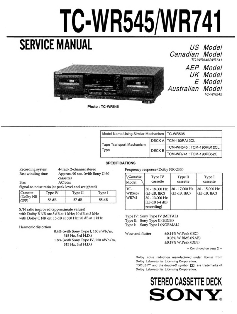
Sony TC-W311 User manual

TC-W3it
SERVICE
MANUAL
US
Model
Canadian
Model
E
Model
Australian
Model
TC-W31ll
is
the
cassette
deck
of
the
SEN-311
system.
>
TC-W31l
is
a
model
designed
based
on
the
TC-W301.
The
mechanical
parts
of
the
TC-W31l
differ
from
those
of
the
TC-W301.
*
For
additional
information
not
contained
in
this
manual,
refer
to
the
TC-W301
Service
Manual.
SPECIFICATIONS
Recording
system
4-track
2-channel
stereo
Frequency
response
(DOLBY
NR
OFF)
With
TYPE
IV
cassette
(Sony
METAL-ES)
30
—
15,000
Hz
(+3
dB)
30
-
13,000
Hz
(0
VU
recording)
With
TYPE
Ii
cassette
(Sony
UCX-S)
30
~
13,000
Hz
(+3
dB)
With
TYPE
|
cassette
(Sony
HF-S)
30
—
13,000
Hz
(+3
dB)
Wow
and
flutter
0.12%
WRMS
(NAB)
Dimensions
Approx.
430
x
120
x
280
mm
(w/h/d)
(17
x
43/4,
x
11
inches)
Weight
Approx.
3.5
kg
(6
Ib.
14
02.)
net
Design
and
specifications
subject
to
change
without
notice.
STEREO
CASSETTE
DECK
SONY.

TC-W311
|
EXPLODED
VIEWS
NOTE:
e
-
XX,
-
X
mean
standardized
parts,
@
{tems
marked
“*”
are
not
stocked
The
components
identified
by
so
they
may
have
some
differences
since
they
are
seldom
required
for
routine
mark
or
dotted
line
with
mark
from
the
original
one.
service.
Some
delay
should
be
anticipated
are
critical
for
safety.
eee
: .
eplace
only
with
part
number
e
Color
Indication
of
Appearance
Parts
when
ordering
these
items.
specified
Example
:
@
The
mechanical
parts
with
no
reference
;
Sees
KNOB,
BALANCE
(WHITE)...(RED)
number
in
the
exploded
views
are
not
Les
composants
identifiés
par
une
‘
marque
sont
critiques
pour
fa
'
f
supplied.
sécurité
Parts
color
Cabinet’s
color
©
@
Hardware
(#mark)
list
is
given
in
the
Ne
les
remplacer
que
par
une
last
of
this
parts
list.
piéce
portant
le
numéro
spécifé.
Refer
to
page
12
of
the
TC-W301
Service
Manual.
(1)
GENERAL
°C)
|
Be
react
ics,
es
eee
wee
os
|
|
Not
supplied
;
|
>
not
supplied
*B
'
Tae
12
19
on
>
5
SS
>
w306
(W301,
306)
S
;
9
<<
:
17
MECHANISM

GENERAL
PARTS
LIST
(Parts
comparison
table
of
TC-W301
and
TC-W311)
TC-W301
12
Ze
25
26
ra
29
30
31
32
33
34
35
903
904
905
t-5o40°
190-1
X-3340-189-1
4-3340-191-1
X-3358-214-1
3-346-379-01
3-346-381-01
3-349-039-01
7-685-133-19
4-928-635-01
4-928-635-21
4-886-821>
11
4-943-424-01
4-943-423-01
7-682-548-09
X-3340-138-1
X-3340-173-1
3-346-265-11
¥07-049-023-2
1
Not
used
Not
used
*4-943-088-31
3-704-366-01
3-499-042-XX
7-685-646-79
X-4904-496-1
Not
used
3-558-708-11
3-549-452-00
a>
(ol=437=11
Not
used
*A-2006-071-A
¥A-2006-138-A
1-574-724-11
1-574-723-11
1-548-596-61
TC-W311
<—
Identical
—
Identical
X-33862-786-1
Identical
—
Identical
f
Identical
Identical
Identical
Identical
Identical
f
t
Not
used
Identical
Identical
Identical
Identical
Identical
rot
a
a
i
Identical
¥3-349-023-51
¥3-349-023-61
¥3-349-023-71
t
Identical
<—
Identical
<—
Identical
Not
used
X-4941-228-1
3-359-928-01
<—
Identical
<—
Identical
<—
Identical
1590453
7-11
*¥A-2006-468-A
*¥A-2006-528-A
12590-48771)
1=590-538-11
<—
Identical
Description
LID
(A)
ASSY,
CASSETTE
LID
(B)
ASSY,
CASSETTE
PANEL
ASSY,
FRONT
PLATE
ASSY,
ORNAMENTAL
KNOB
(SLIDE)
BUTTON
KNOB
(VOL)
SCREW,
+tBTP
2.6X6
TYPE2
N-S
SCREW,
+BV
(2,6X8)
TAPPING
SCREW,
+BV
(2.
6X10)
TAPPING
SCREW,
S
TIGHT,
+PTTWH
3X6
BUTTON
(BLOCK
B)
BUTTON
(BLOCK
A)
SCREW,
+BVTT
3X8
(S)
FOOT
ASSY
(US,
Canadian)
FOOT
ASSY
(E,
AUS)
HOLDER,
PC
BOARD
PANEL,
BACK
(US)
PANEL,
BACK
(CND)
PANEL,
BACK
CE,
AUS)
CASE
SCREW
(CASE)
(M3X8)
BELT,
COUNTER
SCREW,
+BVTP
3X8
TYPE
2
FOOT
ASSY
FELT
(CONDUCTIVE
FELT)
WASHER,
STOPPER
PULLEY,
SHUT-OFF
WASHER
CORD
WITH
CONNECTOR
(US)
MOUNTED
PCB,
AUIDIO
(US,
E,
AUS)
MOUNTED
PCB,
AUIDIO
(Canadian)
WIRE,
FLAT
TYPE
(17
CORE)
WIRE,
FLAT
TYPE
(
7
CORE)
COUNTER,
TAPE
(MIDDLE
TYPE)
«
AUS:
Australian
|
TC-W311

TC-W311
|
ELECTRICAL
PARTS
LIST
Parts
comparison
table
of
TC-W301
and
TC-W311
Page
TC-W301
TC-W311
16
|
C34l
1-126-301-11
ELECT
IMF
20%
50V
|
C341
1-126-233-11
ELECT
22MF
20%
50V
C501
1-126-233-11
ELECT
4.
7MF
20%
50V
|
C501
1-126-233-11
ELECT
22MF
20%
50V
CN6O1
*1-566-856-11
SOCKET,
CONNETOR
5P
(SYSTEM
CONTROL
1)
CN601
*1-566-856-41
SOCKET,
CONNECTOR
5P
(SYSTEM
CONTROL
1)
(BLU)
|
|
CN604
1-568-439-11
SOCKET,
CONNECTOR
‘
CN604
1-568-826-11
SOCKET,
CONNECTOR
7P
CN605
1-568-440-11
SOCKET,
CONNECTOR
17P,
CN605
1-568-836-11
SOCKET,
CONNECTOR
17P
|
CN608
1-568-438-11
SOCEKT,
CONNECTOR
17P
|
CN608
1-568-860-11
SOCKET,
CONNECTOR
17P
CN609
1-568-437-11
SOCKET,
CONNECTOR
7Pj
CN609
1-568-850-11
SOCKET,
CONNECTOR
7P
D401
8-719-107-94
DIODE
18$202-1
—°
|
D401
8-719-987-63
DIODE
1N4148M
17
|
D402
8-719-107-94
DIODE
18$202-1
D402
+
=8-719-987-63
DIODE
1N4148M
D501
S-719=107-94
DIODE
188202-1
D501
8-719-987-63
DIODE
1N4148M
D504
8-719-107-94
DIODE
1882021
D504
8-719-987-63
DIODE
1N4148M
D505
8=719=107-94
DIODE:
1$8202-1
D505
8-719-987-63
DIODE
1N4148M
D506
BH
FLO=tOT
304
IDLODE
2S5202-1
D506
8-719-987-63
DIODE
1N4148M
D507
S-719-107-94
DIODE
7S8202-1
D507
8-719-987-63
DIODE
1N4148M
D510
8-719-107-94
DIODE
188202-1
D510
8-719-987-63
DIODE
1N4148M
D512
8-719-107-94
DIODE
18$202-1
D512
8-719-987-63
DIODE
1N4148M
D516
Oo
Tio-10T-94,
DEORE
ISs202=1
D516
8-719-987-63
DIODE
1N4148M
D518
8-719-107-94
DIODE
18$202-1
D518
8-719-987-63
DIODE
1N4148M
19.
|
3302
beGtlo2t-2
SWITCH.
SLIDE
§302
L=-570-S74-11.
SWITCH,
SLIDE
:
(DECK
A
TAPE
SELECT)
(DECK
A
TAPE
SELECT)
English
P
91D1641
-
1
|
Sony
Corporation
Printed
in
Japan
9-956-
406-11
Audio
Group
©
1991.4
Published
by
Customer
Relations
and
Service
Group
hey,
ae

Be
z
Peon
a
oma
SERVICE
MANUAL
TC-
W306
is
the
cassette
deck
section
in
SEN-501.
Photo
:
TC-W301
is
the
cassette
deck
section
in
SEN-301.
SPECIFICATIONS
Recording
system
4-track
2-channel
stereo
Fast-forward
and
rewind
time
Approx.
120
sec.
(with
C-60
cassette)
Bias
AC
bias
Signal-to-noise
ratio
(NAB,
at
peak
level)
TYPE
IV
(Sony
METAL-ES)
peegP
m:08
TYPE
II
(Sony
UX-S)
|
56
dB
63
dB
TYPE
|
(Sony
HF-S)
61
dB
Total
harmonic
distortion
1.0%
(with
Sony
METAL-ES
cassette)
Frequency
response
(DOLBY
NR
OFF)
TYPE
IV
cassette
|
30-—
15,000
Hz
(+3
dB)
(Sony
METAL-ES)
|
30—
13,000
Hz
(OVU
recording)
TYPE
Il
cassette
|
30-—14,000
Hz
(+3
dB)
(Sony
UX-S)
TYPE
|
cassette
|
30-—13,000
Hz
(+3
dB)
(Sony
HF-S)
Wow
and
flutter
0.12%
WRMS
(NAB)
Input
(TC
—
W306)
connect
[Te
Seeiiy
[teas
LINE
IN
77.5
mV
(~20
dB)
|
50
k
ohms
TC-
W306
US
Model
TC-
W301
TC-
W306
Canadian
Model
E
Model
Australian
Model
TC-
W301
Model
Name
Using
Similar
Mecanism
TC-
W295/
W390
W301
:
TCM-
180VAH1
W306
:
TCM-
180VAH5
Tape
Transport
Mechanism
Type
W301
:
TCM-
180VBH1
W306
:
TCM-
180VBH5
Output
(TC
—-
W306)
Rated
output
level
|
Load
impedance
LINE
OUT
0.44
V(—5
dB)
at
load
impedance
47
k
ohms
|
over
10
k
ohms
General
(TC
—
W306)
Power
requirements
120
V
AC,
60
Hz
Power
consumption
15
W
Dimensions
Approx.
430
x
118
x
250
mm
(w/h/d)
(17
x
43/,x
97/,
inches)
including
projecting
parts
and
controls
Weight
Approx.
3.4
kg
(7
Ibs
8
oz)
Dolby
noise
reduction
manufactured
under
license
from
Dolby
Laboratories
Licensing
Corporation.
“DOLBY”
and
the
double-D
symbol
DM)
are
trademarks
of
Dolby
Laboratories
Licensing
Corporation.
STEREO
CASSETTE
DECK
ONY.

TC-
W301
/
W306
:
SERVICING
NOTE
FOR
TC-W301
{To
supply
B+
voltage
]
When
this
model
alone
operates,
connect
the
unit
to
the
regulated
DC
power
supply,
since
power
of
this
model
is
fed
from
TA-AX301.
5-pin
DC
input
connector
®
12V
to
regulated
dc
power
supply
SAFETY-RELATED
COMPONENT
WARNING!!
COMPONENTS
IDENTIFIED
BY
MARK
A
OR
DOTTED
LINE
WITH
MARK
A
ON
THE
SCHEMATIC
DIAGRAMS
AND
IN
THE
PARTS
LIST
ARE
CRITICAL
TO
SAFE
OPERATION.
REPLACE
THESE
COMPONENTS
WITH
SONY
PARTS
WHOSE
PART
NUMBERS
APPEAR
AS
SHOWN
IN
THIS
MANUAL
OR
IN
SUPPLEMENTS
PUB-
LISHED
BY
SONY.
ATTENTION
AU
COMPOSANT
AYANT
RAPPORT
A
LA
SECURITE!
LES
COMPOSANTS
IDENTIFIES
PAR
UNE
MARQUE
/\
SUR
LES
DIAGRAMMES
SCHEMATIQUES
ET
LA
LISTE
DES
PIECES
SONT
CRITIQUES
POUR
LA
SECURITE
DE
FONCTIONNEMENT.
NE
REMPLACER
CES
COM-
POSANTS
QUE
PAR
DES
PIECES
SONY
DONT
LES
NUMEROS
SONT
DONNES
DANS
CE
MANUEL
OU
DANS
LES
SUPPLEMENTS
PUBLIES
PAR
SONY.
of
TC-W301
from
TA-AX301.
SAFETY
CHECK-OUT
After
correcting
the
original
service
problem,
perform
the
following
safety
check
before
releasing
the
set
to
the
customer:
Check
the
antenna
terminals,
metal
trim,
‘“‘metallized”’
knobs,
screws,
and
all
other
exposed
metal
parts
for
AC
leakage.
Check
leakage
as
described
below.
LEAKAGE
TEST
The
AC
leakage
from
any
exposed
meta!
part
to
earth
ground
and
from
all
exposed
metal
parts
to
any
exposed
metal
part
having
a
return
to
chassis,
must
not
exceed
0.5mA
(500
microampers).
Leakage
current
can
be
measured
by
any
one
of
three
methods.
1.
A
commercial
leakage
tester,
such
as
the
Simpson
229
or
RCA
WT-S540A.
Follow
the
manufacturers’
instructions
to
use
these
instru-
ments.
tro
A
battery-operated
AC
milliammeter.
The
Data
Precision
245
digital
multimeter
is
suitable
for
this
job.
3.
Measuring
the
voltage
drop
across
a
resistor
by
means
of
a
VOM
or
battery-operated
AC
volt-
meter.
The
“limit”
indication
is
0.75
V,
so
analog
meters
must
have
an
accurate
low-
voltage
scale.
The
Simpson
250
and
Sanwa
SH-63Trd
are
examples
of
a
passive
VOM
that
is
suitable.
Nearly
all
battery
operated
digital
multimeters
that
have
a
2V
AC
range
are
suitable.
(See
Fig.
A)
To
Exposed
Metal
Parts
on
Set
AC
voltmeter
{0.75
V)
=
Earth
Ground
Using
an
AC
voltmeter
to
check
AC
leakage.

SECTION
1
ADJUSTMENTS
1-1.
MECHANICAL
ADJUSTMENTS
PRECAUTION
1.
Clean
the
following
parts
with
a
denatured-alcohol-moistened
swab:
record/playback
head
pinch
roller
erase
head
rubber
betls
capstan
idlers
Torque
Measurement
(DECKS
A
and
B)
Gas
aoe
seis
ne
1-2,
ELECTRICAL
ADJUSTMENTS
1.
Demagnetize
the
record/playback
and
erase
head
with
a
head
demagnetizer.
2.
Do
not
use
a
magnetized
screwdriver
for
the
adjustments.
3.
After
the
adjustments,
apply
suitable
locking
compound
to
the
parts
adjusted.
4.
The
adjustments
should
be
performed
with
the
rated
power
supply
voltage
unless
otherwise
noted.
5.
The
adjustments
should
be
performed
in
the
order
given
in
this
service
manual.
(Asa
general
rule,
playback
circuit
adjustment
should
be
completed
before
performing
recording
circuit
adjust-
ment.)
6.
The
adjustments
should
be
performed
for
both
L-CH
and
R-CH.
@
Switches
and
controls
should
be
set
as
follows
unless
otherwise
specified.
DOLBY
NR
switch:
OFF
TAPE
SELECT
switch:
TYPE
I
(NORMAL)
e
Standard
Record:
Deliver
the
standard
input
signal
level
to
the
input
jack
and
set
the
REC
LEVEL
control
to
obtain
the
standard
output
signal
level.
—
Record
Mode
—
af
osc
LINE
OUT
LINE
IN
Note:
Before
recording
short
CN505
with
a
lead
wire,
otherwise
MUTING
functions
and
output
signal
does
not
appear
at
LINE
OUT
terminals.
Standard
Input
Level
G35V
1008
Standard
Output
Level
load
impedance
.
47kQ
output
level
0.44V
(—5dB)
Record/Playback
Head
Azimuth
Adjustment
2-CH
Procedure:
1.
Mode:
FWD
playback
test
tape
P-4-A100
(10
kHz,
-10
dB)
‘
LINE
OUT
2.
Turn
the
adjustment
screw
and
check
output
peaks.
If
the
peaks
do
not
match
for
L-CH
and
R-CH,
turn
the
adjustment
screw
so.
that
outputs
match
within
1
dB
of
peak.
within
1d8
:
Output
level
”
within
1
dB
—
screw
position
Screen
pattern
—
in
phase
45°
90°
135°
180°
ye
YS
good
wrong
3.
After
the
adjustment,
apply
suitable
locking
compound
to
the
adjustment
screw.
Adjustment
Location:
cs
SATURN
REALS
Adjustment
screw
Test
Tape:
Level
Adjustment
[LINE
IN/OUT
for
TC-
W301
]
:
CN321
@)L-ch
LINE
OUT
Tape
Speed
Adjustment
@A-ch
LINE
OUT

TC-W301
/
W306
2-1.
SEMICONDUCTOR
LEAD
LAYOUTS
Tape
Speed
Adjustment
DECK
A
Record
Bias
Current
Adjustment
|
DECK
B
|
Record
Level
Adjustment
DECK
B
.
DECK
B
;
CXA1100P
2S8C945-P
Procedure:
Setting:
Setting:
CXA1198AP
2SC1815Y
:
REC
LEVEL
control:
standard
record
(See
page
3.)
TC4051BPHB
2SD1387
Mode:
FWD
playback
rai
a
I
(
pag
REC
LEVEL
control:
standard
record
(See
page
3.)
test
tape
counter
Procedure:
ener
0B)
1.
Mode:
record
Procedure:
16
1514131211109
1.
Mode:
record
AF
OSC
blank
tape
12345678
CS-
122
AF
ose
(Top
view)
é
c
blank
tape
e
attenuator
CS-122
LINE
OUT
ae]
o
attenuator
ig
al
1,
Short
the
pins
of
CN504
with
a
wire
to
set
the
high
speed
mode.
6002
1Oo0°0
Cf
——
IRSESAS
eat?
LINE
IN
600
2
Vs
Be
A
a
:
1)
315
He
Measurement
limits:
high
speed
2)
10kHez
}
0.025
V
(-30
08)
LINE
IN
315
Hz,
0.025V(—30d8
Speed
checker
Digital
frequency
counter
s
;
/
Ls}
6,000
+
20
Hz
2.
Mode:
playback
lea)
RS
155
123456789
ti
Frequency
difference
between
the
beginning
and
the
end
of
the
(recorded
in
step
1.)
2.
Mode:
playback
{\
tape
should
be
within
1.5%
(90
Hz).
CS-122
Boece
(recorded
in
step
1.)
Adjustment
Location:
0
see
DECK-A:
RV501
LA3160
HZS6A1L
DECK-B:
RV503
LINE
OUT
2.
Remove
the
wire
in
step
1.
(CN504)
Measurement
limits:
|
normal
speed
Speed
checker
Digital
frequency
counter
3000
#10
i
Frequency
difference
between
the
beginning
and
the
end
of
the
Playback
the
tape
record
in
step
1.
If
the
measurement
limits
is
not
satisfied,
adjust
C408-1
(L-CH),
C408-2
(R-CH)
and
repeat
steps
1
and
2.
Measurement
limits
:
The
LINE
OUT
level
of
10
kHz
signal
relative
to
that
of
315
Hz:
-0.5
dB
to
0.5
dB.
LINE
OUT
Playback
the
tape
recorded
in
step
1.
If
the
measurement
limits
is
not
satisfied,
adjust
RV141
(L-CH),
RV241
(R-CH)
and
repeat
steps
1
and
2.
If
the
level
difference
between
the
channels
is
still
1
dB
or
more,
divide
it
to
the
both
channels
on
the
basis
of
—5
dB.
f/f
‘
ALIAN\N.
GELS
HZL11CH2
i
cathode
anode
tape
should
be
within
1.5%
(45
Hz).
sMegsurementumits:
LINE
OUT
level:
0.041
-
0.045
V
(-25
+
0.5
dB)
Adjustment
Location:
MC14066BCP
SEL1210S-C
»PD4011BC
SEL1910A-C
DECK-A:
RV502
TC4001BP
DECK-B:
RV504
3.
If
the
specifications
are
not
satisfied,
repeat
step
1
and
2.
Adjustment
Location:
peg
tz
1410
9B
long
short
[AUDIO
BOARD]
~
COMPONENT
SIDE
—
se
4567
(Top
view)
cathode
anode
RV141:
REC
Level
Adj,
L-CH
Playback
Level
Adjustment
*
i
RV503:
High
Speed,
Deck
B
Procedure:
RV501:
High
Speed,
Deck
A
2SC3623A-
LK
SEL4214S
Mode:
FWD
playback
RV502:
Normal
Speed,
Deck
A
test
t.
:
:
P4300
RV504:
Normal
Speed,
Deck
B
RV241:
REC
Level
Adj.,
R-CH
ak
(315
Hz,
0d8)
CN504:
High
Speed
Mode
RV102:
PB
Level
Adj.,L-CH,
Deck
B
RV202:
PB
Level
Adj.,
R-CH,
Deck
B
C408:
REC
BIAS
Current
Adj
ee
&
1
ANODE
LINE
OUT
Ee
2
CATHODE
RV101:
PB
Level
Adj.,
L-CH
Deck
A
Adjust,
RV201:
PB
Level
Adj.,
R-CH,
Deck
A
DECK-A:
RV101
(L-CH),
RV201
(R-CH)
DTA114ES
1SS202-
1
DECK-B:
RV102
(L-CH),
RV202
(R-CH)
nied
nae
10E2N
so
that
the
measurement
limits
are
satisfied.
DTC144ES
2SC2603-
EF
Measurement
limits:
LINE
OUT
level:
0.180
-
0.146
V
(-15
+
0.5
dB)
level
difference
between
the
channels:
within
0.5
dB
cathode
anode

TC-
W301
/
W306
@®
SEMICONDUCTOR
LOCATION
2-2.
PRINTED
WIRING
BOARDS
®@
See
page
5
for
semiconductor
lead
layouts.
|
Ret.
No.
|
No,
|
Location
|
C4
1C194
D-4
|
|
|
y
|
3
i
4
|
5
|
6
|
7
|
8 9
lO
|
|
|
|
I2
ioe
we
|
14
“|
118
|
16
|
a
18
a
9
|
{C291
0-3
DECK
A
ae
ms
—
DECK
B—
K
A
Note
on
Mounting
Diagram:
1C301
1C302
HPIOL
A
PLAYBACK
HEAD
(DECK
A}
1C303
1C322
1C341
10342
1C501
1C502
PR
Note:
@
O-——
+:
parts
extracted
from
the
component
side,
@
{
=:
parts
mounted
on
the
conductor
side,
HRPIO}
RECORD
/
PLAYBACK
.
HE40]
HEAD
1
ERASE
HEAD
Q101
Q121
Q141
Q201
Q221
Q241
Q321
Q401
Q402
Q403
Q404
Q405
501
Q502
Q503
Q504
Q505
Q506
Q507
Q508
Q509
Q511
Q512
Q601
Q602
Q603
Q605
[METER
BOARD]
[
{AUDIO
BOARD
]
METER.-UNIT_.
pIs5
nena
Oe
cece
a
tg
ane
&
f
ms
y
Sa
atl
Lp
eh
-
soo
anv
een
Ma
RAEI
am
Ri
:
ie
Ce
:
oP
a
ut
a
PoC,
Din
casas
tent
rarcapaacasncneruaegnasinessiyT
et
of
ecient
bm
“C323
ee
nner)
pect
Fat
Mec
tena
et
See
remanicetapasnatnytng,.
stating,
Say,
Cece
eed
ped
sie
Sh,
a
je
te,
nancsintionareat
tat
ivmunearaiscesrioncucngasntt
teyesaranarncaceaghntdnaaeys®
GUUUCULeuetitital
3
.
°
Agha
ieasusver atin
i
_
age
Se
a
|
|
1
1
i)
i
Bi
a
ee
TC-W301
i:
-3|
|
e
|
IP
[gfe
|}
|
tecwsol
Canadian
MODEL
/\
ae
—
Be
i
aa
CES
lessee
4
US,E,Australion
MODEL,
|
-wi0s!
O+-
©
O+-©!
l
ay,
CJ!
|
tc-w306
MODEL
MODEL
|
Tope
|
@
ol
J
|
TC-W306
[SraTER
CN6OI
J
|
CN321
|}
j
Ce)
_[t)
aa
L
SYSTEM
U
|
eee
eee
jones
ee
LN
evan
it}
|
Soe
MODEL
TC-W306
7s
eee
a
ae
MODEL
oe
ts
$904
—
DECK
A—
DECK
B
aor
M902
M901
$905
J
REEL/
CAPSTAN
ee
REEL/CAPSTAN
S905
(FWD)
~
t
gy
t
Sy
aw
3
5
RS
oO
62
a8
g)
26

2-3.
SCHEMATIC
DIAGRAM
HPIOI
Lech
=
PTY
Late
a
ee
P
ee
an
SET
C
HRPIOL
B-DECK
REC/PB-HEAD
Lch
[AUDIO
BOARD}
%
C301,
302
TC-wW301
100n
25V
TC-W306
MODEL
!
i
|
100
16V
1
MODEL
16303
(Ol
sa
|
@
sisis2)
|
@]
55,0156)
|
©)
Sissaset
ess
—
[siacs2v7@[
si
|
Q121
28C2603
LINE
OUT
MUTING
13
DOLBY
NR
LINE
out
MUTING
1c301
1@|
Ko)
LA3160
fo)
[
(2
222
|
fercren|
PB EQ
AMP
fo)
fe)
ian
aso,
L@L_
sno
Tet
ie]
(1/2)
220
1/2
:
gz!
2
i
coz
ay
fF
Sov
|
SOV
L
1
|
ios
=
10%
SOV
iw
ls
|
47
|
2,
54
°Sov
16303
a>
5
ize
Pe
Be
bers
W4086BP
C103
fe
A/B
SELECT
8
+]
CN301
es
Cis
‘
—
——
Ky
C101
$8103
Ta
_|
4.7
S0V
ae
is
Lal
36007
F270K
Rio2T RTOs!
c1os
a
RY
:
3
a
82
°F
5.
6k!
0.0228
RViot
Rexeze)
¢104
C301
10x
G+
|
1o0x4
ae:
02
8
C2
10s
Sov
|
R204
C205
5.
6k
0.
0228
¥20
10k
x
R
220
it,
S2's
4.78
SOY
302
(1720)
10303
(274)
SWITCHING
e303
1000p
T
PB
LEVEL
DECK
B(L}
R114
100k
10303
(3/4)
SWITCHING
\.
TAPE-B1:0
OTHERS
.3
cx6os
1d
creos
<«G-
One
[
METER
BOARD
]
on9
0,0
L
L
| i
RV321-1
RI3I
tk
R121
33k
20K
ax
ul
R231
tk
R221
33k
min
‘Hr
(2}-6}
RV321-2
20K
4_}
2)
DI9I—
D196
SEL42144S-C-TP3
!
AUX
aias
R192
100
kc
;
CH321
ba
R391
ze
R235
La
asa
nae
4
560
ox. lox
lose
Let
ot
°3
‘3k
Toure"
siesninalibesiniy.
umole
Sidi,
|
iiuasitiwipiaipitenle”
soup.
ttmsessietelisansonemestal,
isha
ey
Sa
J
Cy
ey
C7 ey
am
ae
mG
[ye]
D196]
D194]
Di92
Rese
l
Ca}
tig
e191
Ld
i
man
2,28
O-—)—-)
)-
OOH
OD)
50V
» »
-
4
44
ry
One®
98
98
8398
0
fe
C227
2.2%
SOV
TC-W30!
rocco
Kexez.
3)
[REC
LEVEL
ADJ(L)
|
LEVEL
ADJ(L)
Qt4)
Rion
2sc2608
MUTING
REC
EQ
AMP
tp
‘SOV
TC-
H
MOO!
fag
10p
50V
0241
TC-W306
2SC2603
4
0.7
9
R349
R350
S6k
62k
R3SS
R356
82k
75k
MODEL
MUTING
i
a
ee
er)
—
Oak
|
METER
DRIVE
Heh
83
0
1C291
IR2ESIA
Seep
Rive
Kom
ksh
{C291
D291
—
D296
SEL42148-C-TP3.
OF
F~eON
$303
[DOLBY
_NR)
Rch
=
>
|
Ke)
of
°
R207
R209
C211
6.52!
boy
MODEL
H
|
PPE
So
0.022%
i
—
+20
vee
|
t
|
o
| &
|
R
{S600)
270
da
corn
|
NR
O
'
209
}9-8_
R208
c
amoleaferfon]
|,
7)
|
al
|
be
een
oa
0
-_
a
DECK
BIR)
Fea
ét4y|<20>]<32>}
11
$22?
—
3
ar
TAPE
~BI:0
Or@
<i
|c209|<32)
W632
i
162
%y
1
10302
rises
S
OTHERS
$10.5
Lt
(2/2)
a
|}
L131
27H
SATS
8
TAPE.
B10
:
88
¢
1
=
Hl
4
y
Ly
Cis
3
!
6146
75p
630v
T
'80
g
©
i
S
3
$301
|
|
€246
7S»
630v
é
i
i
TYPE
_LTYPE
|
TYPE
des
A
se
ace
a
hoe
ttn
tet
ote
PON
ee
2th
Ao
ete
Shee
adore
metus
|
a
171
"yy
940)
asciaiey
TPE
2
2en1345
F
a1AS
OSC”
BIAS
DRIVE
SWITCH
ee
ed
TAPE~BIL/IV
1.2
TAPE-BIV
.0
HIGH
SPEED
0
I
)
=)
150
}
OTHERS
1.2
NORMAL
SPEED
:8.3
$301-3
gy¥ee
ya
re,
$301=4
Dor]
¥
0
33-15)
(Ss132|
PCIE
in Mm
R408
R410
12k
330
nie
a
BIAS
OSC
t
\
$302
=
[nich
SPEED
DECK
A}
DSOS
R10
G
I
DEcK=
A.
HIGH
SPEED
DECK
A
RVSO2
1$8132
68k
2
7
2
2
=
1
NORMAL
SPEED
DECK
A
.
wees
scan
cls
SNSO!
“al
R502
M401
1BP
M4001BP
ists]
TYPE
_,
TYPE
=
‘an
av501
a
180
CONTROL
LOGIC
CONTROL
LOGIC
out
I
“ayy
2.
2k
Los
AY
M901
ears
|
ACD
ra
A
MOTOR
ul
Ds1é
$501
|
REEL/
Ome
am
«>
Be
at
psos
SP
paig
1€S01
(3/4)
1¢502
4/4)
IDUBB
I
CAPSTAN
an
fetstekn
Ile
502
ieso2
Gan]
188182
= =
at
=
—
SEL12108-1P3
8503
IC501
474)
t
egewee
R515
RES
12
ao
|
ft]
|
dll
UP
|
pee
eee
ee
+
ee
fe
A
FWD
SW
11.2
2SAl345
i
7
600
og’
-
SWITCHING
|
TC-W306
MODEL
|
ey
3
a)
©
(eee
coer
eey
Gor
D601
D602
2
ri
ANY
T
4
H
|
26012
f6034
10E2-TA2 1OE2-TA2
@
=
H
rs
DECK
B
l
|
Ca
REGULATOR
7
|
2
AC
IN
1
a508-
y
©)
kay
=
1
cuso2
ascsaae
250800,
R6OS|
wh)
:
-
oI
:
id
D604 D603
re
ee
SLi
|
TC-W306
MODEL
Rog6g
10K
g
128°
Od)
1OE2-TA2\
4
082-72
Airs:
M902
NE
tavsoa
POON
fp
Neen
}
B
MOTOR
(M)
elo
A
POWER
1
ORSTAN
os
H
1
TRANSFOMER
H
)
$904
?
1?
tL
“ua
Wee
BNICaM
[SWITCH
BOARD
}
B
FWD
SW
S
19}
(9.6)
:
_
1
r
o
(O}
ee
sw
°
CK602
CHEOS
|
|
ICSO1
(2/74)
1}
oF
vey
7!
\
3
wy
-—-———
Re
eee
ee
12)
oJ
a
y
$60!
RBA
~2
i
0,
<i>
28A1348
|
;
:
o
zara}
!
0,
11.8)
R518
29e4dop
11-8
aso?
40.1)
OFF
ON
|
11.8,
AZB
tO)
“REMOTE
PAUSE
eencninge,
tt
SE
8
a
ET
ERI
ee
og
site
tre
Rae
see
a
rg
ple
Sty
eae
etme
eo
etn
aa
_
11.8,
BIO)
|
ee
R550
1,
8
(the)
Nu
dO
ee
SST
TT
OT
eran
ray
|
cxsor
f
b/--~---—
=
10,
<0>
11.8
<VCC>
aaseie
|
LATOR
|
I
0506
AU
|
J
2sAl345
—_
Bil.8)
SWITCHING
|
_|SWITCHING
a7
lev
I
heoa
'1C-W301
WOTOR
@
|
R7024
$R507
‘C-W301
MODEL,
“{TH2-TPE
trali
Te-
|
O,BtIIt)
H
ts
38
i
pliers:
A
Ee
en
|
C-W30l
MODEL
SYSTEM
CONTROL
1
J
@)
0,A/8
11.8)
=
lids
|
TC-W306
MODEL
MODELS
SS
pe
ep
6)
o,<i1.2>
[@]
18,
a7B0)
TTc-w306
nee
=
———
I
Ssap
ee
a
a
pa
= = = =
|
©]
0,
av2>
[@3]
1.8,
07810)
|
MODEL
COO
1
[@L_
cxo
{Ol
ne
wee)
Ei
erage
trees
ernie
ae
J
es
0
TC
~W306
MODEL
16
17
Note
on
Schematic
Diagram:
Note:
TC-W301
/
W306
All
capacitors
are
in
uF
unless
otherwise
noted.
pF:
uur
SOWV
or
less
are
not
indicated
except
for
electrolytics
and
tantalums.
All
resistors
are
in
2
and
1/,W
specified.
("_]}:
adjustment
for
repair.
or
less
unless
otherwise
AC
voltage
readings
in
the
bias
oscillator
with
a
VTVM.
Voltage
and
waveforms
are
dc
with
respect
to
ground
under
no-signal
conditions.
no
mark:
STOP
A(
):
PB
(DECK
A}
B(
):
PB
(DECK
8)
<
>:
REC
(DECK
B)
f
]:
DUBBING
(NORMAL}
{{
lH}:
DUBBING
(HIGH)
Voltages
are
taken
with
a
VOM
(Input
impedance
10M).
Voltage
variations
may
be
noted
due
to
normal
produc-
tion
tolerances.
Signal
path.
X>
:PBIDECK
A)
[>
:PBI(DECK
B)
(>>
:
REC
(DECK
B)
Note:
The
components
identi-
fied
by
mark
or
dot-
ted
line
with
mark
are
critical
for
safety.
Replace
only
with
part
number
specified.
Note:
Les
composants
identifiés
par
une
marque
sont
critiques
pour
la
sécurité.
Ne
les
remplacer
que
par
une
piéce
portant
le
numéro
spéci-
fié.

_TC-W301
/W306
|
NOTE:
@
The
mechanical
parts
with
no
reference
number
in
the
exploded
views
are
not
supplied.
e
The
construction
parts
of
an
assembled
part
are
indicated
with
a
collation
num-
ber
in
the
remark
column,
@
[tems
marked
"*"
are
not
stocked
since
they
are
seldom
required
for
routine
service.
Some
delay
should
be
antici-
pated
when
ordering
these
items.
SECTION
3
EXPLODED
VIEWS
®
Due
to
standardization,
parts
with
part
number
suffix
-XX
and
-X
may
be
dif-
ferent
from
the
parts
specified
in
the
components
used
on
the
set.
@
Color
Indication
of
Appearance
Parts
Example:
(RED)...
KNOB,
BALANCE
(WHITE)
t
t
Cabinet's
Color
Parts’
Color
@
AUS:
Australian
model
The
components
identified
by
mark
or
dotted
line
with
mark
are
critical
for
safety.
eplace
only
with
part
number
specified.
Les
composants
identifiés
par
une
marque
sont
critiques
pour
la
sécurité,
Ne
les
remplacer
que
par
une
piéce
portant
le
numéro
spécifé.
(1)
GENERAL
No.
Part
No.
Description
Remarks
No.
Part
No.
Description
Remarks
]
X-3340-190-1
LID
(A)
ASSY,
CASSETTE
22.
=
*3-349-023-21
=
(W301)...PANEL,
BACK
2
X-3340-189-1
LID
(B)
ASSY,
CASSETTE
*3-349-023-31
(W306)...PANEL,
BACK
3
X-3340-191-1
(W301)...PANEL
ASSY,
FRONT
23.
-*3-327-855-01
(W306)...COVER
(TRANSFORMER)
X-3346-302-1
(W306)...PANEL
ASSY,
FRONT
24
=
*3-703-571-11
=(W306)...BUSHING
(S)
(4516),
CORD
25
3-327-856-61
CASE
4
3-354-912-01
(W306)...KNOB,
POWER
5
X~3358-214-1
PLATE
ASSY,
ORNAMENTAL
26
3-704-366-01
SCREW
(CASE)
(M3X8)
6
3~346-379-01
KNOB
(SLIDE)
27
3-499-042-XX
BELT,
COUNTER
7
3-346-381-01
BUTTON
28
7-621-849-00
(W306)...SCREW,
TAPPING
8
3-349-039-01
KNOB
(VOL)
29
7-685-646~79
(W301)...SCREW,
+BVTP
3X8
TYPE
2
9
7-685-133-19
SCREW
+BTP
2.6X6
TYPE2
N-S
30
X-3340-138-1
(W301:US,Canadian,W306)...FOOT
ASSY
1]
4-928-635-01
SCREW,
+BV
(2.6X8}
TAPPING
X-3340-173-1
(W301:E,AUS).
0...
cece
wees
FOOT
ASSY
12
4-928-635-21
SCREW,
+BV
(2.6X10)
TAPPING
13
7-682-548-04
(W306)...SCREW
+BVTT
3X8
(S)
901
*A~2006-071-A
(W301:US,E,AUS)...MOUNTED
PCB,
AUDIO
*A-2006-072-A
(W306).......
e+e
eMOUNTED
PCB,
AUDIO
14
4~886-821-11
(W301)...SCREW,
S
TIGHT,
+PTTWH
3X6
*A-2006-138-A
(W301:Canadian)...MOUNTED
PCB,
AUDIO
7-682-548-09
(W306)...SCREW,
+BVTP
3X8
(S)
903
1-574-724-11
WIRE,
FLAT
TYPE
(17
CORE)
17
3-349-043-11
BUTTON
(BLOCK
B)
904
1-574-723-11
WIRE,
FLAT TYPE
(7
CORE)
18
3-349-042~-11
BUTTON
(BLOCK
A)
905
1-548-596-61
COUNTER,
TAPE
(MIDDLE
TYPE)
19
7-682-548-09
SCREW
+BVTT
3X8
(S)
CP]
A.1-558-945-711
(W306)...CORD,
POWER
(POLAR.SPT-1)
20
X-4904-496-1
FOOT
ASSY
T6071
A.1-449-256-11
(W306)...
TRANSFORMER,
POWER
21
=
*3-346-265-11
HOLDER,
PC
BOARD
26
DECKA
MECHANISM
18
S240
not
supplied
not
supplied
17
MECHANISM

(2)
MECHANISM
SECTION-
1
TCM-
180VA-H1
(W301),
(W301),
No.
301
302
303
304
305
306
307
DECK
A:
DECK
B
:
304
303
Part
No.
3-358~271-01
3-358~-266-01
3-358-209-01
7-685-103-19
7~-685-132-19
X-3358-214-]
7-621
-775-20
TCM-
180VB-
H1
Description
Remarks
No.
LEVER
(BUTTON
BASE
A)
|
308
HOLDER,
CASSETTE
309
SPRING
(CASSETTE
HOLDER),
LEAF
310
SCREW
+P
2X5
TYPE2
NON-SLIT
311
(DECK
A)...SCREW
+BTP
2.6X5
TYPE2
N-S
|
906
(DECK
A)...PLATE
ASSY,
ORNAMENTAL
M901
M902
SCREW
+B
2.6X5
=o
TCM-180VA-HS
(W306)
TCM-
180VB-H5
(W306)
Part
No.
7~685-133-19
3-358-272-01
3-358-287-01
3-358
-242-01
*1
-635-158-11
X-3358-212-1
X-3358-212-1
Description
308
M901:
M902:
309
DECK
A
DECK
B
Remarks
SCREW
+BTP
2.6X6
TYPE2
N-S
BELT
(A2)
SPRING
(LOADING
A),
TORSION
SHAFT
(BUTTON
SHAFT)
PC
BOARD,
SW
MOTOR
(B)
ASSY
MOTOR
(B)
ASSY

(3)
MECHANISM
SECTION-2
No.
351
352
353
354
355
356
357
358
359
360
361
Part
No.
37319-224-31
7-623-921-01
3-358
~232-01
*3~358-204-01
3-358
~-259-01
3-358-258-01
3-358-257-01
3-358-256-01
3-358-260-01
*3-358-226-01
*3-358-261-01
364
361
359
Description
DAMPER,
SMALL
WASHER
1.7,
NYLONE
SPRING
(S-P
F-R),
TORSION
(DECK
B)...LEVER
(REC
SAFETY)
(DECK
B)...SLIDER
(REC)
SLIDER
(FF)
SLIDER
(STOP/EJECT)
SLIDER
(PAUSE)
LEVER
(PAUSE
LEVER)
SLIDER
(HOLDER
LOCK)
)
)
SLIDER
ay
(
Remarks
No.
362
363
364
365
366
367
368
369
370
eee
|).
eee
Part
No.
*X~3358~-213-]
3-701
-437-01
X-3358-205-~1
7-685-133719
*3-358-249-01
37-358-214-01
37358
-233~01
3-358-230-01
X~3358-202-]
*3-358-286-01
Description
Remarks
BRACKET
(A)
ASSY
WASHER
FLYWHEEL
(A)
ASSY
SCREW
+P
2.6X6
TYPEI
SLIDER
(LOCK
PLATE)
(DECK
A)...SPRING
(LOCK),
TORSION
(DECK
B)...SPRING
(REC-LOCK),
TORSION
BELT
(Al).
LEVER
(FR
ARM)
ASSY
LEVER
(MOTOR
LEVER)

(4)
MECHANISM
SECTION-3
408—P
F409
407
409
DECK
B:
oo
DECK
A:
406
No.
401
402
403
404
405
406
4Q7
408
409
410
41]
412
413
Part
No.
3~358~243-01
*3-358-253-01
X-3358-204-1
*3-358-215-01
3-358-265-01
3-358
-285-01
37358~234-01
37358-213-01
7-685-105-19
7~623-505-01
*3-358-251-01
3-358
-208
-01
*3-358-270-01
Description
—
410
<p
_
7
403
SPRING
(TU-SHUT),
TORSION
LEVER
(SHUT-OFF
LEVER)
LEVER
(PINCH
LEVER)
ASSY
BUSHING
(WIRE
KIT
RETAINER)
SLIDER
(HEAD
PC
BOARD
A)
(DECK
A)...GUIDE,
TAPE
SPRING
(AZIMUTH),
COMPRESSION
SCREW,
AZIMUTH
TPG
+P
2X8,
TYPE
2,
NON-SLIT
LUG,
2
LEVER
(TENSION
DETECTION
ARM)
SPRING
(SUPPLY),
COMPRESSION
(DECK
B)...PULLEY
(COUNTER
PULLEY)
DECK
A
Cr
(ie
.
{
|
HRP101:
DECK
B
i
A14
Remarks
No.
414
415
416
47
418
419
420
421
422
HE401
HPTO1
422
402
not
supplied
|
Part
No.
Description
Remarks
3-358-248-01
GEAR
(SUPPLY
REEL)
X-3358-203-1
TABLE
(7)
ASSY,
REEL
37358~228-01
SPRING,
TORSION
*3-358-284-01
*3~358~-252-01
*3-358-255-01
*3~358-224-01
3-358
-207-01
3-358-227-01
1-543-673-11
1~543-672-11
HRP101
17543-672-11
=
TC-W301
/
W306
420
GEAR
(TU
GEAR)
LEVER
(TU
ARM)
(DECK
B)...LEVER
(GB
LEVER)
GEAR
(FF
GEAR)
SPRING
(FF
GEAR),
COMPRESSION
SPRING,
LEAF
HEAD,
MAGNETIC
(ERASE)
HEAD,
MAGNETIC
(REC/PB)
HEAD,
MAGNETIC
(REC/PB)

TC-
W301
/W306
NOTE:
SECTION
4
ELECTRICAL
PARTS
LIST
e
Due
to
standardization,
replacements
in
the
parts
list
may
be
different
from
the
parts
specified
in
the
diagrams
or
the
components
used
on
the
set.
@e
items
marked
“x”
are
not
stocked
since
they
are
seldom
required
for
routine
service.
Some
delay
should
be
anticipated
when
ordering
these
items.
e
If
there
are
two
or
more
same
circuits
in
a
set
such
as
a
stereophonic
machine,
only
typical
circuit
parts
may
be
indicated
and
capacitors
and
resistors
in
other
same
circuits
may
be
omitted.
Ref
.No,
901
903
904
905
906
Clol.
C102
C103
C104
C105
C106
C107
C108
C109
C110
ci
C112
C113
C114
C115
C116
C121
C126
Cl27
.
C128
C141
C142
C143
C144
C145
C146
C191
C192
C201
C202
C203
C204
C205
C206
C207
C208
€209
C210
C21
Part
No.
*A-2006~-071-A
*A-2006-072-A
*A~2006-138-A
1-574-724-11
1~574-723-11
1-548-596-61
*]
-635-158-11
1~162-291-31
1-126-059-11
1-162-282-31
1-124-994-11
1-136-157-00
1-126-161-11
1-162~-291-3}
1-126-059~11
1-162~282-3]
1-124-994-11
1-136-157-00
1-126-161-11
1-161-377-00
1-162-289-31
1-124-045-00
1-124-045~-00
1-126-161-11
1-131~587-11
1-124-257-00
1-126-161-11
1-136-173-00
1-124-045-00
1-124-994~11
1-126~-059-11
1-162-284~31
1-136-273~91
1-126-161-11
1-126-059-11
1162-291
-31
1-126-059~11
1-162-282-3]
1-124-994-11
1-136-157-00
1-126-161-11
1~162-291~31
1-126-059-11
1-162~-282-31
1-124-994-1]
1-1367-157-00
Description
(W301:US,E,AUS)...MOUNTED
PCB,
AUDIO
(W306)......0++..MOUNTED
PCB,
AUDIO
(W301:Canadian)...MOUNTED
PCB,
AUDIO
WIRE,
FLAT
TYPE
(17
CORE)
WIRE,
FLAT
TYPE
(7
CORE)
COUNTER,
TAPE
(MIDDLE:
TYPE)
PC
BOARD,
SW
CERAMIC
560PF
10%
ELECT
1
OMF
20%
CERAMIC
100PF
10%
ELECT
100MF
20%
FILM
0.022MF
5%
ELECT
2.
2MF
20%
CERAMIC
560PF
10%
ELECT
1
OMF
20%
CERAMIC
100PF
10%
ELECT
100MF
20%
FILM
0.022MF
5%
ELECT
2.
2MF
20%
CERAMIC
O.0047MF
20%
CERAMIC
390PF
10%
ELECT
4.
7MF
20%
ELECT
4.
7MF
20%
ELECT
2.
2MF
20%
TANTALUM
0.
68MF
10%
ELECT
2.2MF
20%
ELECT
2.
2MF
20%
FILM
0.47MF
5%
ELECT
4.
7MF
20%
ELECT
100MF
20%
ELECT
1
OMF
20%
CERAMIC
150PF
10%
FILM
75PF
5%
ELECT
2.
2MF
20%
ELECT
1
OMF
20%
CERAMIC
560PF
10%
ELECT
1
OMF
20%
CERAMIC
100PF
10%
ELECT
1
0OMF
20%
FILM
O.022MF
5%
ELECT
2.
2MF
20%
CERAMIC
560PF
10%
ELECT
1
OMF
20%
CERAMIC
100PF
10%
ELECT
1O0MF
20%
FILM
O.022MF
5%
CAPACITORS:
MF:
uF,
PF:
wyF.
RESISTORS
@
All
resistors
are
in
ohms.
e@
F:
nonflammable
COILS
e@
MMH:
mH,
UH:
wH
SEMICONDUCTORS
In
each
case,
U:
yw,
for
example:
UA...:
wA...,
UPA...:
uPA...,
The
components
identified
by
mark
or
dotted
line
with
mark
are
Critical
for
safety.
eplace
only
with
part
number
specified.
Les
composants
identifiés
par
une
marque
sécurité.
Ne
les
remplacer
que
par
une
piéce
portant
le
numéro
spécifié.
sont
critiques
pour
la
UPC...:
wPC,
UPD...:
uPD...
Ref.No.
Part
No.
C212.
1-126-161-11
C213):
1-161-377-00
C214
=.
1-162-289-3)
C215
=
=1-124-045-00
C216
=
1-124
-045-00
C22]
1-126-161-11
C226
=.
1-131
-587-11
50V
C227)
=
1-124-257-00
50V
C228
=:
1-1
26-161-11
50V
C24)
1-136-173-00
TOV
C242
=
1-124-045-00
50V
C243:
1-124-994-11
50V
C244
=—s-
1-1
26-059-11
50V
C245
=:
1
-162-284-31
50V
C246
=.
1-136
-273-91
50V
C29}
1-126-161-11
10V
C292.)
1-126-059-11
50V
50V
C301
1-124-478-11
C301
1-126-023-11
16V
50V
C302.
=:
1-124-478-11
50V
C302)
=:
1-126-023-11
50V
C303.
1-162-294-31
50V
C322
=
1-126-101-11
35V
C323):
1-124-045-00
50V
C341
1-126-059-11
50V
C34)
1-126-301-1)
50V
C39]
1-126-059-11
50V
C40}
1-136-562-11
10V
C402)
=
-1-126~-301-11
50V
C403.
=:
1-130-482-00
50V
C404
=:
1-1
30-478-00
630V
C405
=:
1
-130-478-00
50V
C406
=.
1-126
-300-11
50V
C407
1-126-161-11
50V
C408
=.
1-141
-225~-00
50V
C501
1-124-045-00
50V
C502)
=
1-126-059-11
10V
C601
1-124-962-11
50V
C602
1-126-012-11
50V
C603)
-1~124-478-11
50V
C604
=
1-124-910-11
50V
C605
=:
1-124-910-11
50V
C605
~=—s-
1-126
-022-1)
10V
50V
C606
=:
11-126
-024-11
C70)
1-124-045-00
*
AUS:
Australian
model
Description
ELECT
2.2MF
20%
50V
CERAMIC
0.0047MF
20%
16V
CERAMIC
390PF
10%
50V
ELECT
4.7MF
20%
50V
ELECT
4.
7MF
20%
50V
ELECT
2.2MF
20%
50V
TANTALUM
0
.68MF
10%
35V
ELECT
2.2MF
20%
50V
ELECT
2.2MF
20%
50V
FILM
0.4
7MF
5%
50V
ELECT
4.
7MF
20%
50V
ELECT
1OOMF
20%
10V
ELECT
1
OMF
20%
50V
CERAMIC
150PF
10%
50V
FILM
75PF
5%
630V
ELECT
2.2MF
20%
50V
|
ELECT
1
OMF
20%
50V
(W306)...ELECT
JOOMF
20%
25V
(W301)...ELECT
100MF
20%
16V
(W306)...ELECT
100MF
20%
25V
(W301)...ELECT
100MF
20%
16V
CERAMIC
0.001
MF
10%
50V
ELECT
220MF
20%
10V
ELECT
4.7MF
20%
50V
(W306)...ELECT
=
10MF
20%
50V
(W301)...ELECT
=
IMF
20%
50V
ELECT
1
OMF
20%
50V
FILM
0.0082MF
5%
630V
ELECT
IMF
20%
50V
MYLAR
0.0082MF
5%
50V
MYLAR
0.003
9MF
5%
50V
MYLAR
0,0039MF
5%
50V
ELECT
0.4
7MF
20%
50V
ELECT
2.2MF
20%
50V
CAP,
TUNING,
TRIMAR
ELECT
4.
7MF
20%
50V
ELECT
1
OMF
20%
50V
(W306)...ELECT
2200MF
20%
25V
ELECT
470MF
20%
16V
(W306)...ELECT
100MF
20%
25V
(W306)...ELECT
47MF
20%
25V
(W306)...ELECT
47MF
20%
25V
(W301)...ELECT
47MF
20%
16V
ELECT
220MF
20%
16V
(W306)...ELECT
4.7MF
20%
50V

Ref
.No.
CN301
CN302
CN321
CN40}
CN503
CN504
CN505
CN601
CN602
CN604
CN605
CN608
CN609
CN901
CN902
CPI
D191
D192
D193
D194
D195
D196
0291
D292
D293
0294
D295
D296
D401
0402
D501
D504
D505
D506
D507
D510
D511
D512
D513
D514
D515
D516
D517
D518
D601
D602
D603
D604
D605
D606
D607
D608
HE401
HP101
Part
No,
*1~564~507-11
*1
~564~-509-11
*1-566-856~11
*1-564-505-11
*1~566-210-11
*1-564-505-11
*1~564-505-11
*]
-566-856-11
*]
-564-337-00
1-568-439-11
1~568-440-11
1~568~438-11
1-568
-437-1]
*1
-564~-499-11
*1~564-500-11
A.1-558-945-1]
8~719-304~32
8-719-304-32
8-719-304-32
~719-304-32
-719~304-32
~719~304-32
8
8
8
8-719-304~32
8~719-304-32
8-719-304-32
8~-719-304-32
8-719~304-32
8-719~304-32
8-719-107-94
.
8-719-107-94
8-719-107~94
8-719~107-94
8-719-107-94
8-719-107-94
8-719-107~94
8-719-107-94
8-719-107-94
~719-107~94
~719-107~94
-719-302-46
8
8
8
8-719-302-79
8~719-107-94
8-719-107-94
8-719-107-94
8-719-200-77
8-719-200-77
8-719-200-77
8~719-200-77
8-719-933~33
8-719-200-77
8-719~200-77
8-719~001-54
1-543-673-11
1-543~672-11
HRP1O1
1-543-672-11
Description
PLUG,
CONNECTOR
4P
PLUG,
CONNECTOR
6P
(W301)...SOCKET,
CONNECTOR
5P
(SYSTEM
CONTROL
2)
PLUG,
CONNECTOR
2P
(W306)...PIN,
CONNECTOR
3P
(SYSTEM
CONTROL)
PLUG,
CONNECTOR
2P
PLUG,
CONNECTOR
2P
(W301)...SOCKET,
CONNECTOR
5P
(SYSTEM
CONTROL
1)
(W306)...PIN,
CONNECTOR
3P
SOCKET,
CONNECTOR
7P
SOCKET,
CONNECTOR
17P
SOCKET,
CONNECTOR
17P
SOCKET,
CONNECTOR
7P
PIN,
CONNECTOR
6P
PIN,
CONNECTOR
7P
(W306)...CORD,
POWER
(POLAR.SPT-1)
DIODE
DIODE
DIODE
SEL4214S
SEL4214S
SEL4214S
DIODE
DIODE
DIODE
SEL4214S
SEL4214S
SEL4214S
DIODE
DIODE
DIODE
SEL4214S
SEL4214S
SEL4214S
DIODE
DIODE
DIODE
SEL42145
SEL4214S
SEL4214S
1$S$202-1
1SS202~1
1$S202-1
DIODE
DIODE
DIODE
DIODE
DIODE
DIODE
1$S202-]
1SS8202-1
1SS202-1
DIODE
1SS202~]
DIODE
1SS202-]
(W306)...DIODE
1SS202-1
DIODE
1SS202~1
(W306)...DIODE
1$S202-1
DIODE
SEL1210S-C
(W306)...DIODE
SEL1910A-C
DIODE
1SS202-1
DIODE
1SS202-1
DIODE
1$S202-1
(W306)...DIODE
10E2N
(W306)...DIODE
10E2N
(W306)...DIODE
10E2N
(W306)...DIODE
10E2N
(W306)...DIODE
HZS6ATL
(W301)...DIODE
10E2N
(W301)...DIODE
10E2N
(W301
:US,E,AUS,W306)...DIODE
UZL-11H2
HEAD,
MAGNETIC
(ERASE)
HEAD,
MAGNETIC
(REC/PB)
HEAD,
MAGNETIC
(REC/PB)
RefNo.
1¢191
{C291
1C30]
T€302
1C303
10322
1034]
10342
1¢50]
[C502
J32]
L131
L231
M901
M902
9101
9121
014)
Q201
Q221
Q241
Q321
0401
Q402
Q403
Q404
Q405
Q501
Q502
Q503
Q504
Q505
9506
Q507
Q508
Q509
0511
0512
601
Q602
Q603
Q605
R101
R102
R103
R104
R106
R107
R108
R109
R110
R11
R112
R113
R114
R12]
R122
Part
No,
8-759-917-42
8-759~917~-42
8-759-800~36
8-759-800~36
8-759~000-49
8-752-031
-67
8-752-038-02
8-759-208-06
8~-759~-140-11
8-759~240-01
1~565~-258-11]
1-410-780-11
1-410-780-11
X-3358-212-1
X-3358-212-1
8-729~-900~89
8~729-620-05
8~-729-620-05
8-729~-900-89
8-729-620~05
8-729-620-05
8-729-900-89
8-729~-194-57
8-729-194-57
8-729-281~52
8-729-900-65
8-729~900-80
8-729-900-65
8-729-900-65
8-729~-900-61
8-729-801
-93
8-729-900-89
8-729-900-65
8-729-900-89
8-729~900-80
8-729-900~65
8-729-900~80
8-729-900-89
8-729-209-15
8-729~209-15
8-729-141
~30
8-729-620~05
1-247-889~-00
1-249-404-00
1-247-882~11
1-249-426-11
1-247-889-00
1-249-404-00
1-247-882-11
1-249-426~11
1-249~430-11
1-249-431-11
1-247-887-00
1-249~441-11
1-249~441-11
1-249-435-11
1-249-417-1)
Note:
The
components
identi-
fied
by
mark
ted
line
with
mark
are
critical
for
safety.
Replace
only
with
part
TC-
W301
/
W306
Nescription
IC
ER2E31A
IC
IR2E31A
IC
LA3160
IC
LA3160
IC
MC14066B
IC
CXA1100P
IC
CXAT198A
IC
104051BP
IC
UPD40118
IC
TC4001BP
(W306)...JACK,
PIN
4P
(LINE
IN/OUT)
INDUCTOR
INDUCTOR
MOTOR
(B)
A
MOTOR
(B)
A
TRANSISTOR
TRANSISTOR
TRANSISTOR
TRANSISTOR
TRANSISTOR
TRANSISTOR
TRANSISTOR
TRANSISTOR
TRANSISTOR
TRANSISTOR
TRANSISTOR
TRANSISTOR
TRANSISTOR
TRANSISTOR
cP
P
HB
C
27MMH
27MMH
SSY
SSY
DTCI44ES
2SC02603-EF
2802603
~EF
DTC144ES
2SC2603
~EF
2SC2603~EF
DTICI44ES
-
2SC945~P
28C945-P
2SC1815Y
DTAI44ES
DICII4ES
DTAl44ES
DTAL44ES
(W306)...
TRANSISTOR
DTAI14ES
(W306)...
TRANSISTOR
2801387
(W306)...
TRANSISTOR
DTC144ES
(W306)...
TRANSISTOR
DTAI44ES
TRANSISTOR
DTC144ES
(W306)...
TRANSISTOR
DTC114ES
TRANSISTOR
DTAI44ES
(W306)...
TRANSISTOR
DICI14ES
(W306)...
TRANSISTOR
DTC144ES
(W306)...
TRANSISTOR
2802012
(W301:US,E£
,US,W306)..
TRANSISTOR
2SD2012
(W306)...
TRANSISTOR
2SC3623A~LK
(W306)...
TRANSISTOR
2SC2603-EF
CARBON
CARBON
CARBON
CARBON
CARBON
CARBON
CARBON
CARBON
CARBON
CARBON
CARBON
CARBON
CARBON
CARBON
CARBON
270K
5%
82
5%
130K
5%
5.6K
5%
270K
5%
82
5%
130K
5%
5.6K
5%
12K
5%
15K
5%
220K
5%
100K
5%
TOOK
5%
33K
055%
IK
3%
Note:
Les
composants
identifiés
par
une
marque
A\
sont
critiques
or
dot-
number
specified.
fie.
pour
la
sécurité.
Ne
les
remplacer
que
par
une
piéce
portant
le
numéro
spéci-
1/4W
1/4W
1/4W
1/4W
1/4W
1/4W
1/4W
1/4W
1/4W
1/4W
1
/4W
1/4W
1/4W
1/4W
1/4W

TC-
W301
/W306
Ref
.No.
R129
R130
R13]
R132
R133
R134
R135
R141
R142
R144
R145
R191
R192
R201
R202
R203
R204
R206
R207
R208
R209
R210
R211
R212
R213
R214
R221
R222
R229
R230
R23)
R232
R233
R234
R235
R241
R242
R244
R245
R291
R292
R301
R302
R32]
R322
R323
R324
R341
R342
R343
R344
R345
R346
R347
R348
R349
R350
Part
No.
1-249-421-11
1-249-429-11
1-249-417-11
1~249~429-1]
1-249-421-1]
1249-4341]
1-247-842-1711
1-249~426-11
1-249~-421-11
1-249-421-11
1-249~430-11
1-249-441-11
1~249-405-11
1-247-889-00
1-249-404-00
1-247-882-11
1-249-426-11
1-247-889-00
1-249-404-00
1-247-882-11
1-249-426-1]
1-249-430-11
1-249-431-1]
1-247-887-00
1-249-441-11
1249-441
-11
1-249-435-11
1-249-417-11
1-249-421-11
1-249-429-11
1-249-417-11
1-249~429~11
1-249-421-11
1~249-434-11
1-247-842-11
1-249~426-1)
1-249-421-1]
1-249-421-11
1-249~430-11
1-249-441-11
1-249~405-11
1-247-743-11
1-247-743-1]
1-249~-433-11
1-215-460~-00
1-247-876-11
1-249-405-11
1-249-441-11
1-247-864-11
1-247-887~-00
1-247-882-11
1-247-881-00
1-249-440-11
1-249-435-11
1-249-438-1]
1-249~438-11
1-247-874-11
Description
CARBON
CARBON
CARBON
CARBON
CARBON
CARBON
CARBON
CARBON
CARBON
CARBON
CARBON
CARBON
CARBON
CARBON
CARBON
CARBON
CARBON
CARBON
CARBON
CARBON
CARBON
CARBON
CARBON
CARBON
CARBON
CARBON
CARBON
CARBON
CARBON
CARBON
CARBON
CARBON
CARBON
CARBON
CARBON
CARBON
CARBON
CARBON
CARBON
CARBON
CARBON
CARBON
CARBON
CARBON
METAL
CARBON
CARBON
CARBON
CARBON
CARBON
CARBON
CARBON
CARBON
CARBON
CARBON
CARBON
CARBON
2.2K
10K
IK
10K
2.2K
27K
3K
5.6K
2.2K
2.2K
12K
100K
100
270K
82
130K
5.6K
270K
82
130K
5.6K
12K
15K
220K
100K
100K
33K
1K
2.2K
10K
IK
10K
2.2K
27K
3K
5.6K
2.2K
2.2K
12K
100K
100
220
220
22k
43K
75K
100
100K
24K
220K
130K
120K
82K
33K
56K
56K
62K
5%
5%
5%
5%
5%
5%
5%
5%
5%
5%
5%
5%
5%
5%
5%
54
54
5%
5%
5%
5%
5%
5%
5%
5%
5%
5%
5%
5%
5%
5%
5%
Sh
5%
5%
5%
5%
5%
5%
5%
5%
5%
5%
5%
1%
5%
5%
5%
5%
5%
5%
5%
5%
5%
5%
5%
1/4W
1/4W
1/4W
1/4W
1/4W
1/4W
1/4W
1/4W
1/4W
1/4W
1/4W
1/4W
1/4W
1/4W
1/4W
1/4W
1/4W
1/4W
1/4W
1/4W
1/4W
1/4W
1/4W
1/4W
1/4W
1/4W
1/4W
1/4W
1/4W
1/4W
1/4W
1/4W
1/4W
1/4W
1/4W
1/4M
1/4W
1/4W
1/4W
1/4W
1/4W
1/2W
1/2W
1/4W
1/6W
1/4W
1/4W
1/4W
1/4W
1/4W
1/4W
1/4W
1/4W
1/4W
1/4W
1/4W
1/4W
Ref
.No.
—18—
R351
R352
R353
R354
R355
R356
R357
R358
R359
R360
R36]
R362
R363
R364
R365
R366
R367
R368
R369
R370
R371
R372
R373
R374
R375
R376
R377
R378
R379
R380
R381
R391
R401
R402
R403
R404
R405
R406
R408
R409
R410
R50)
R502
R503
R504
R505
R506
R507
R509
R510
R51]
R512
R513
R514
R515
R516
R517
Part
No.
1-249-436-11
1-247-874-1)
1+247-870-11
1-249-439-11
1-249-440-11
1-247-876-1)
1-247-876-11
1-249~437-11
1-249-434-11
1~-249~-438-11
1-247~881-00
1-249-440-1)
1-247-882-11
1-247-872-11
1-249-437-11
1-249~436-11
1-249~438-11
1-249-439-11
1-247-876-11
1-249~437-11
1-247-876-11
1-249-438-11
1-249-441-11
1-247-890-11
1-249-436-11
1247-881
-00
1-247-881~-00
1-247-881-00
1-249-437-11
1-249-437-11
1-249~433-1]
1-249-414-1]
1249-39311
1-249~433~-11
1-249-433-11
1-247-858-1)
1-249-417-11
1~249-433-11
1~249-430-11
1-249-426-11
1-249-411-11
1-249~420-11
1-249-408-11
1-249-425-11
1-249-420-11
1-249-408-11
1-249-425-11
1-249~393-1]
1-249-421-11
1~-249-427-1)
1-249~435-11
1-249-440-11
1-249~429-1]
1-249-441
-1]
1-249-415-11
1-249~442~-1]
1-249-421-11
Description
CARBON
39K
CARBON
62K
CARBON
43K
CARBON
68K
CARBON
82K
CARBON
75K
CARBON
75K
CARBON
47K
CARBON
27K
CARBON
56K
CARBON
120K
CARBON
82K
CARBON
130K
CARBON
51K
CARBON
47K
CARBON
39K
CARBON
56K
CARBON
68K
CARBON
75K
CARBON
47K
CARBON
75K
CARBON
56K
CARBON
100K
CARBON
300K
CARBON
39K
CARBON
120K
CARBON
120K
CARBON
120K
CARBON
47K
CARBON
47K
CARBON
22K
CARBON
560
CARBON
10
CARBON
22K
CARBON
22K
CARBON
13K
CARBON
1K
CARBON
22K
CARBON
12K
CARBON
5.6K
CARBON
330
CARBON
1.8K
CARBON
180
CARBON
4.7K
CARBON
1.8K
CARBON
180
CARBON
4.7K
(W306).
..CARBON
(W306)...CARBON
CARBON
6.8K
CARBON
33K
CARBON
82K
CARBON
10K
CARBON
100K
CARBON
680
ee
eee
W306)...CARBON
5%
5%
5%
5%
5%
5%
5%
5%
5%
5%
5%
5%
5%
5%
5%
5%
5%
5%
5%
5%
5%
5%
5%
5%
5%
5%
5%
5%
5%
5%
5%
5%
5%
5%
5%
o%
o%
o%
5%
5%
5%
5%
5%
5%
5%
5%
5%
10
2.2K
5%
5%
5%
5%
5%
5%
510
2.2K
1/4W
1/4W
1/4W
1/4W
1/4W
1/4W
1/4W
1/4W
1/4W
1/4W
1/4
1/4W
1/4W
1/4W
1/4W
1/4W
1/4W
1/4W
1/4W
1/4W
1/4W
1/4W
1/4W
1/4W
1/4W
1/4W
1/4W
1/44
1/4W
1/4W
1/4W
1/4W
1/4W
1/4W
1/4W
1/4W
1/4W
1/4W
1/4W
1/4W
1/4W
1/4W
1/4W
1/4W
1/4W
1/4W
1/4W
5%
1/4W
5%
1/4W
1/4W
1/4W
1/4W
1/4W
1/4W
1/4W
5%
1/4W
5%
1/4W

Ref
.No.
R518
R520
R521
R550
R570
R603
R604
R605
R606
R607
R608
Part
No.
1-249-417-11
1-249-425-11
1-249~417-11
1-249-429-11
1-247-848-11
1-249-421-11
1-249-421-11
1~249~429-11
1-249-421-11
1-249~421-11
1-249-411-11
R701
A.1-212-942-00
R702
R703
RV101
RV102
RV141
RV201
RV202
RV24]
RV321
RV501
RV502
RV503
RV504
RY401
$301
$302
$303
$501
$60]
$902
$904
$905
T401
1-249-417-11
1-249-421-11
1-228-994-00
1-228-994-00
1-228-994-00
1-228-994
-00
1-228-994-00
1-228~994~-00
1-238-262-11
1-228-991-00
1
-228-990~00
1228-991
~-00
1-228-990-00
1-515-614-11
1-571
-628-11
1-571
-627-21
1-571-510-11
1-571-510-11
1-570-393-21
1-571-736-11
1-571
-736-1)
1-571-736-11
1-433-303~-11
T601
A.17449-256-11
Description
(W306)...CARBON
1K
5%
1/4W
CARBON
4.7K
5%
1/4
(W306)...
CARBON
1K
5%
1/4W
CARBON
10K
5%
=
1/4W
(W306)...CARBON
5.1K
5%
1/4W
(W306)...CARBON
2.2K
5%
1/4W
(W306)...CARBON
2.2K
5%
1/4W
(W306).
..CARBON
10K
5%
1/4W
(W306)...CARBON
2.2K
5%
1/4W
(W306).
..CARBON
2.2K
5%
1/4W
(W301
:US,E,
AUS,
W306)
.
CARBON
330
5%
1/4W
(W301)...FUSIBLE
2.2
5%
1/2W
F
‘
(W306).
..CARBON
1K
5%
1/4W
(W306)...CARBON
2.2K
5%
1/4W
RES,
ADJ,
CARBON
10K
RES,
ADJ,
CARBON
10K
RES, ADJ,
CARBON
10K
RES,
ADJ,
CARBON
10K
RES,
ADJ,
CARBON
10K
RES, ADJ,
CARBON
10K
RES, VAR,
CARBON
20K/20K
(REC
LEVEL)
RES,
ADJ,
CARBON
2.2K
RES, ADJ,
CARBON
1K
RES,
ANUJ,
CARBON
2.2K
RES,
ADJ,
CARBON
1K
RELAY
SWITCH,
SLIDE
(DECK
B
TAPE
SELECT)
SWITCH,
SLIDE
(DECK
A
TAPE
SELECT)
SWITCH,
PUSH
(1
KEY)
(DOLBY
NR)
SWITCH,
PUSH
(1
KEY)(DUBBING
SPEED)
(W306)...SWITCH,
PUSH
(1
KEY)
(POWER)
SWITCH,
LEAF
(A
FUD)
SWITCH,
LEAF
(B
FWD)
SWITCH,
LEAF
(B
REC)
TRANSFORMER,
BIAS
OSCILLATION
(W306)...
TRANSFORMER,
POWER
ACCESSORY
&
PACKING
MATERIAL
1-558-649~11
1-559-533-11
3-703-450-01
*3-704-343-01
3-7517-753-21
(W306)...CORD
(WITH
CONNECTOR)
3P
(W306)...CORD,
CONNECTION
(W306)...
INSTRUCTION
SHEET
(STANDARD),
PROTECTION
(W306)...MANUAL,
INSTRUCTION
Note:
The
components
identi-
fied
by
mark
A
or
dot-
ted
line
with
mark
are
critical
for
safety.
Replace
only
with
part
number
specified.
25416
—
|
TC-W301/W306
Note:
Les
composants
identifiés
par
une
marque
A\
sont
critiques
pour
la
sécurité.
Ne
les
remplacer
que
par
une
piéce
portant
le
numéro
spéci-
fid.

TC-
W301
/W306
|
English
.
90D1673-1
Sony
Corporation
Printed
in
Japan
9-955-684-11
Audio
Group
©1990.4
20
Published
by
Customer
Relations
and
Service
Group
Table of contents
Other Sony Cassette Player manuals

Sony
Sony TCM-900DV Operating Instructions (primary... User manual

Sony
Sony CFS-E14 User manual

Sony
Sony WM-FS555J - Walkman User manual

Sony
Sony TC-WR8ES User manual

Sony
Sony XR-C9100R User manual

Sony
Sony WM-FX321 User manual

Sony
Sony WM-AF22 User manual

Sony
Sony WM-FX673 User manual

Sony
Sony Walkman WM-GX677 User manual

Sony
Sony Walkman WM-EC1 User manual

Sony
Sony CFD-S23 User manual

Sony
Sony TC-WE435 User manual

Sony
Sony TCM-473V User manual

Sony
Sony Walkman WM-EX621 User manual

Sony
Sony TC-SP55 User manual

Sony
Sony TC-FX120 User manual

Sony
Sony TC-KA1ESA - Cassette Deck User manual

Sony
Sony Walkman WM-FX481 User manual

Sony
Sony Walkman WM-EX900 User manual

Sony
Sony TC-K88B User manual