– 21 – – 22 –– 19 – – 20 –
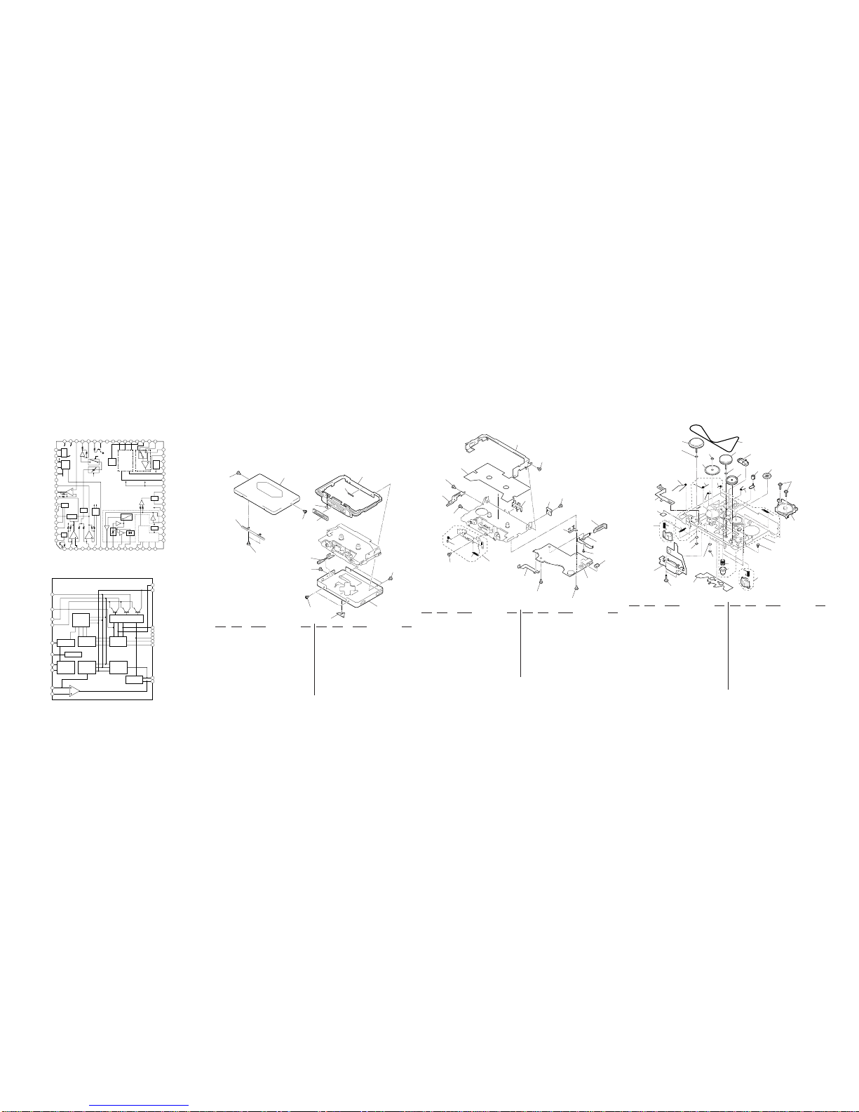
rIC BLOCK DIAGRAMS
IC601 MM1279XVBE
IC301 TA2103F
+
11
13
14
15
16
17
18
20
1
2
3
4
5
6
7
8
9
10
19
12
PRE
DRIVER
SOFT
SWITCH
MOTIVE
LOGIC
MOTIVE
/OSC
BIAS
REFERENCE
VOLTAGE
MOTIVE
CONTROL
CIRCUIT
INVERTER
SPEED
CONTROL
CURRENT
CONTROL
OUTPUT
BIAS
PV
V
PW
W
GND
OSC
DR
VREF
START
VSP
IN+
U
PU
GND
VCC
FC
TC1
TC2
R1
OUT
+
+
+
+
16
15
14
13
12
11
10
9
8
7
6
5
432
1
33
32
31
30
29
28
27
26
25
24
23
22
21
20
19
18
17
49
50
51
52
53
54
55
56
57
58
59
60
61
62
63
64
3435
36373839404142
43
44
45
46
47
48
RIPPLE
FILTER
AGC
DET BST
SW
BEEP
V-I PW
V REF
BASS
SW
AGC DET
PRE
V REF
CH-A CH-B
PRE NF-L
PRE OUT-L
MTL DRV-L
MTL DRV-R
PRE OUT-R
PRE NF-R
F/R SW
DET 1
AMS OUT
AMS HPF
PRE SW
EK IN-R
BUF IN-R
NR SW
BUF IN-L
EK IN-L
DET 2
HIGH SW
BST SW
PW IN-C
BST OUT
BST NF
EQ-R
PW NF-R
VCC1
PRE GND 3
IN-R REV
IN-R FWD
DC SRV-R
PRE VREF
DC SRV-L
IN-R FWD
IN-L REV
EQ-L
PW NF-L
PW IN-L
PRE GND
PW IN-R
PW VREF
RF IN
NR OUT-R
SC IN-R
HPF-R
RECT-R
PRE GND 2
RECT-L
HPF-L
SC IN-L
NR OUT-L
AGC IN
RF OUT
BASE
VCC
PW GND
PW OUT-R
PW OUT-C
PW OUT-L
PW SW
MUTE SW
BEEP
TC
AVLS DET
AVLS IN
AVLS OUT
PRE MTL
DRV
PW C
ALC PW B PW A
EK
D
F
C
G
CH-A NR
CH-B NR
B
SW
MIX
AMS
ADD B
ADD A
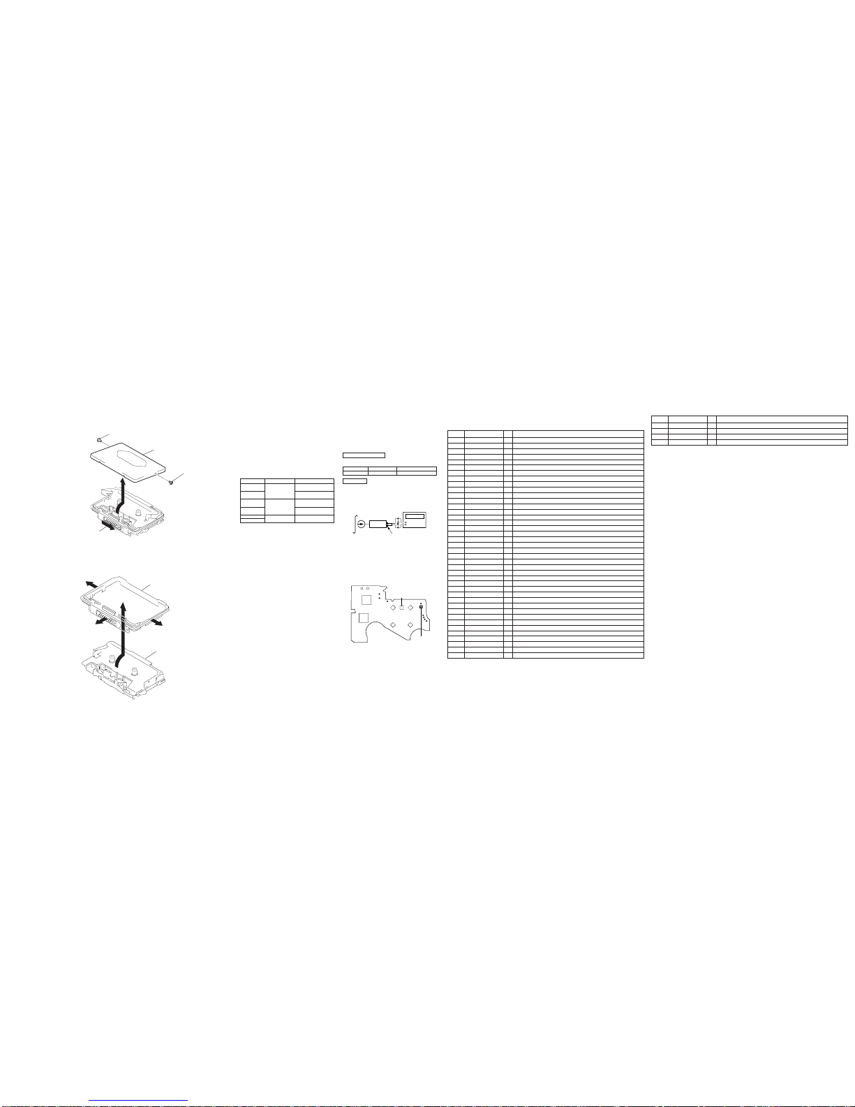
SECTION 6
EXPLODED VIEWS
NOTE :
• -XX, -X mean standardized parts, so they
may have some difference from the original
one.
• Color indication of Appearance Parts
Example :
KNOB, BALANCE (WHITE) ••• (RED)
↑↑
Parts color Cabinet's color
• Items marked “ * ”are not stocked since they
are seldom required for routine service. Some
delay should be anticipated when ordering
these items.
• The mechanical parts with no reference
number in the exploded views are not
supplied.
Ref. No. Part No. Description Remark Ref. No. Part No. Description Remark
6-1. CASE SECTION
Ref. No. Part No. Description Remark Ref. No. Part No. Description Remark
1 3-375-114-61 SCREW
2 X-3374-606-1 CASSET LID ASSY (BLACK) (EX655)
2 X-3374-607-1 CASSET LID ASSY (SILVER) (EX655)
2 X-3374-608-1 CASSET LID ASSY (BLUE) (EX655)
2 X-3374-609-1 CASSET LID ASSY (ORANGE) (EX655)
2 X-3375-608-1 CASSET LID ASSY (BLACK) (EX668)
2 X-3375-609-1 CASSET LID ASSY (SILVER (EX668)
2 X-3375-610-1 CASSET LID ASSY (BLUE) (EX668)
2 X-3375-611-1 CASSET LID ASSY (ORANGE) (EX668)
3 3-704-197-91 SCREW (IB LOCK)•••(SILVER,BLUE,ORANGE)
3 3-939-590-13 SCREW (IB LOCK)•••(BLACK)
4 3-015-913-01 KNOB (OPEN)
5 3-015-912-11 ORNAMENT, REEL
6 3-020-859-01 SPACER (RI)
7 3-939-590-18 SCREW (IB LOCK)•••(SILVER,BLUE,ORANGE)
7 3-939-590-19 SCREW (IB LOCK)•••(BLACK)
8 X-3374-610-1 CASE ASSY (BLACK)
8 X-3374-611-1 CASE ASSY (SILVER)
8 X-3374-612-1 CASE ASSY (BLUE)
8 X-3374-613-1 CASE ASSY (ORANGE)
9 3-015-922-01 KNOB (HOLD)(BLACK)
9 3-015-922-11 KNOB (HOLD) (SILVER)
9 3-015-922-21 KNOB (HOLD) (BLUE)
9 3-015-922-31 KNOB (HOLD) (ORANGE)
10 3-389-523-35 SCREW (IB LOCK)•••(SILVER,BLUE,ORANGE)
10 3-389-523-36 SCREW (IB LOCK)•••(BLACK)
11 3-015-924-01 PLATE, ORNAMENTAL
12 3-021-423-01 CUSHION (PI) (WM-EX655)
51 3-704-197-01 SCREW (IB LOCK)
52 X-3374-062-1 BRACKET ASSY
53 3-016-085-01 BRACKET (C)
54 3-009-662-32 COVER (A), MD (WM-EX668)
54 3-009-662-21 COVER (A), MD (WM-EX655)
55 X-3374-063-1 HOLDER ASSY, CASSETTE
56 3-366-890-01 SCREW (M1.4)
57 3-928-465-01 DETENT, CASSETTE
58 3-007-282-01 TERMINAL BOARD (MINUS),BATTERY
59 3-015-926-01 LID, BATTERY CASE (BLACK)
59 3-015-926-11 LID, BATTERY CASE (SILVER)
59 3-015-926-21 LID, BATTERY CASE (BLUE)
59 3-015-926-31 LID, BATTERY CASE (ORANGE)
60 3-375-114-71 SCREW
61 X-3374-330-1 TERMINAL BOARD ASSY (K)
62 A-3061-556-A AUDIO BOARD, COMPLETE (EX655)
62 A-3061-693-A AUDIO BOARD, COMPLETE (EX668 : FR)
62 A-3021-130-A AUDIO BOARD, COMPLETE
(EX668 : EXCEPT FR)
63 3-019-232-01 SPRING, TENSION
64 3-015-925-01 TERMINAL BOARD
65 3-016-087-02 COVER (SW)
66 3-018-159-01 SPRING, TORSION
S901 1-762-582-11 SWITCH, LEAF (ATS)
101 3-011-277-01 COVER (B) (Y), MD
6-2. AUDIO BOARD SECTION
• Accessories and packing materials are given
in the last of this parts list.
1
3
3
4
5
6
7
7
9
10
11
8
2
not supplied
12
S901
51
51
51
51
51
52
53
54
55
56
57
58
59
60
60
61
62
64
65
66
63
• Abbreviation
FR : French
102 3-704-413-31 SCREW (M1.4X7.2)
103 X-3372-850-1 PINCH LEVER (N) ASSY
104 3-007-434-01 PULLEY (REVERSE)
105 3-007-428-01 WASHER (R)
106 X-3372-851-1 FLYWHEEL (R) ASSY
107 3-007-439-01 SLIDER (LOCK)
108 3-386-694-11 WASHER
109 X-3372-852-1 FLYWHEEL (N) ASSY
110 3-007-430-01 BELT
111 3-007-960-01 SPRING (EJECT) (Y), TORSION
113 3-010-274-02 TABLE, REEL
114 3-007-436-01 SPRING (TRIGGER), TORSION
115 X-3372-848-1 CLUTCH ASSY (M)
116 3-007-435-01 GEAR (FR)
117 X-3372-853-1 LEVER (FRG) ASSY
119 3-007-432-01 SHEET (R), REFLECTION
120 3-007-427-01 SCREW (IB LOCK)
121 X-3374-094-1 CHASSIS (S) ASSY (Y)
Ref. No. Part No. Description Remark Ref. No. Part No. Description Remark
122 3-007-455-01 SPRING (R), TORSION
123 3-007-458-01 SPRING (H/B), TENSION
124 3-007-456-01 SPRING (N), TORSION
125 3-007-454-01 SPRING (FR), TORSION
126 3-007-457-01 SPRING (TEN), TENSION
127 X-3372-849-1 PINCH LEVER (R) ASSY
128 3-010-954-01 SPRING (BT), COMPRESSION
129 3-918-943-01 WASHER, STOPPER
130 3-366-017-01 BUSHING (CAPSTAN)
131 3-007-429-01 WASHER (R), STOPPER
132 3-932-724-21 WASHER
*133 3-010-272-01 BELT, RETAINER
134 3-569-706-01 SPACER, CASSETTE LID
HP901 1-500-280-11 HEAD, MAGNETIC (PLAYBACK)
M901 1-698-885-11 MOTOR
PM901 1-454-674-31 SOLENOID, PLUNGER
6-3. MECHANISM DECK SECTION
(MT-WMEX655-125)
HP901
PM901
M901
101
102
103
104
105
106
107
108
109 110
111
113
114
115
116
117
119
120
121
122
123
124 125
126
127
128
129
130
131
130
132
133
134
Ver 1.1 1998.10