3
ICF-CD543RM
panel (front)
MEGA BASS: Original Type, Silver Type
LIV : Liv Type
TABLE OF CONTENTS
1. SERVICING NOTES .............................................. 3
2. GENERAL .................................................................. 4
3. DISASSEMBLY
3-1. Disassembly Flow ........................................................... 5
3-2. Cabinet (Upper), CD Lid ................................................ 6
3-3. CD Block Section............................................................ 6
3-4. Panel (Front) Section ...................................................... 7
3-5. Holder (MD).................................................................... 7
3-6. CD Board......................................................................... 8
3-7. Chuck Plate Assy ............................................................ 8
3-8. Tray.................................................................................. 9
3-9. Belt, Loading Board........................................................ 9
3-10. Base Unit ......................................................................... 10
3-11. Arm, Optical Pick-up Section (KSM-213RCP) ............. 10
3-12. Optical Pick-up (KSS-213R) .......................................... 11
4. ELECTRICAL ADJUSTMENTS
Tuner Section ................................................................. 12
CD Section ..................................................................... 15
5. DIAGRAMS
5-1. Block Diagram – CD Section – .................................... 17
5-2. Block Diagram – MAIN Section – ............................... 18
5-3. Note for Printed Wiring Board and
Schematic Diagrams ....................................................... 19
5-4. Printed Wiring Board – CD Section – .......................... 20
5-5. Schematic Diagram – CD Section – ............................. 21
5-6. Printed Wiring Boards – RELAY Section – ................. 22
5-7. Schematic Diagram – RELAY Section – ..................... 23
5-8. Printed Wiring Boards – MAIN Section – ................... 24
5-9. Schematic Diagram – MAIN section – ........................ 25
5-10. Printed Wiring Boards – PANEL Section – ................. 26
5-11. Schematic Diagram – PANEL Section – ...................... 27
5-12. IC Pin Function Description .......................................... 32
6. EXPLODED VIEWS
6-1. Cabinet (Upper) Section ................................................. 34
6-2. Panel (Front) Section ...................................................... 35
6-3. Cabinet (Lower) Section ................................................. 36
6-4. CD Block Section............................................................ 37
6-5. CD Mechanism Deck Section
(FLM-CD543RM-149) ................................................... 38
6-6. Base Unit Section............................................................ 39
6-7. Optical Block (KSM-213RCP)....................................... 40
7. ELECTRICAL PARTS LIST .............................. 41
SECTION 1
SERVICING NOTES
MODEL NO. ICF-CD543RM
US, Canadian models: AC: 120 V 60 Hz 15 W
AEP model: AC: 220 – 230 V 50 Hz 15 W
The laser diode in the optical pick-up block may suffer electro-
static break-down because of the potential difference generated
by the charged electrostatic load, etc. on clothing and the human
body.
During repair, pay attention to electrostatic break-down and also
use the procedure in the printed matter which is included in the
repair parts.
The flexible board is easily damaged and should be handled with
care.
NOTES ON LASER DIODE EMISSION CHECK
The laser beam on this model is concentrated so as to be focused
on the disc reflective surface by the objective lens in the optical
pick-up block. Therefore, when checking the laser diode emis-
sion, observe from more than 30 cm away from the objective lens.
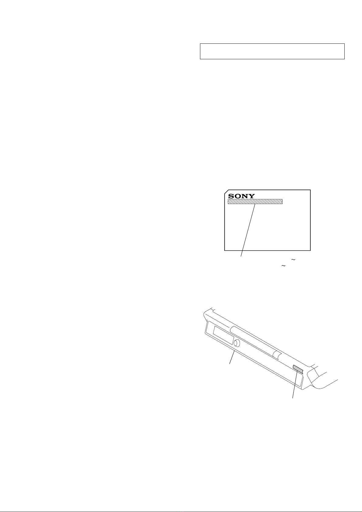
MODEL IDENTIFICATION –Top View –
NOTES ON HANDLING THE OPTICAL PICK-UP
BLOCK OR BASE UNIT
There are three types of US model.
Please look at the mark of set shown below.