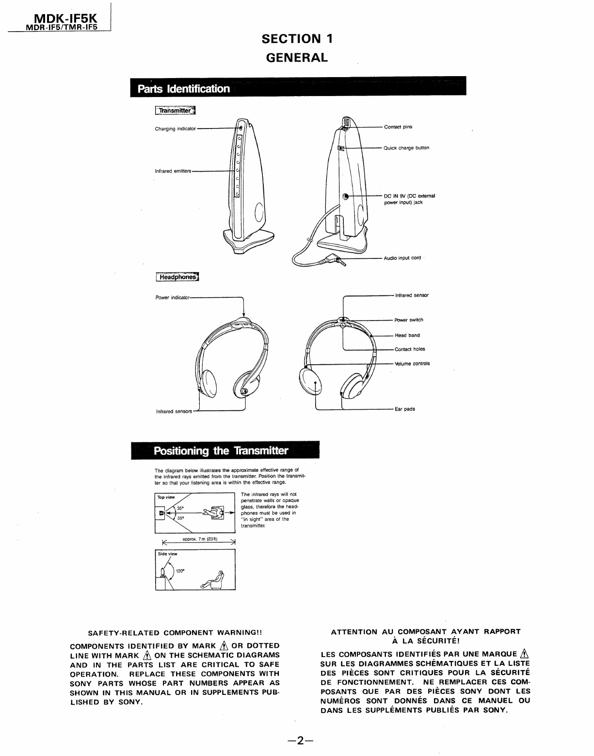
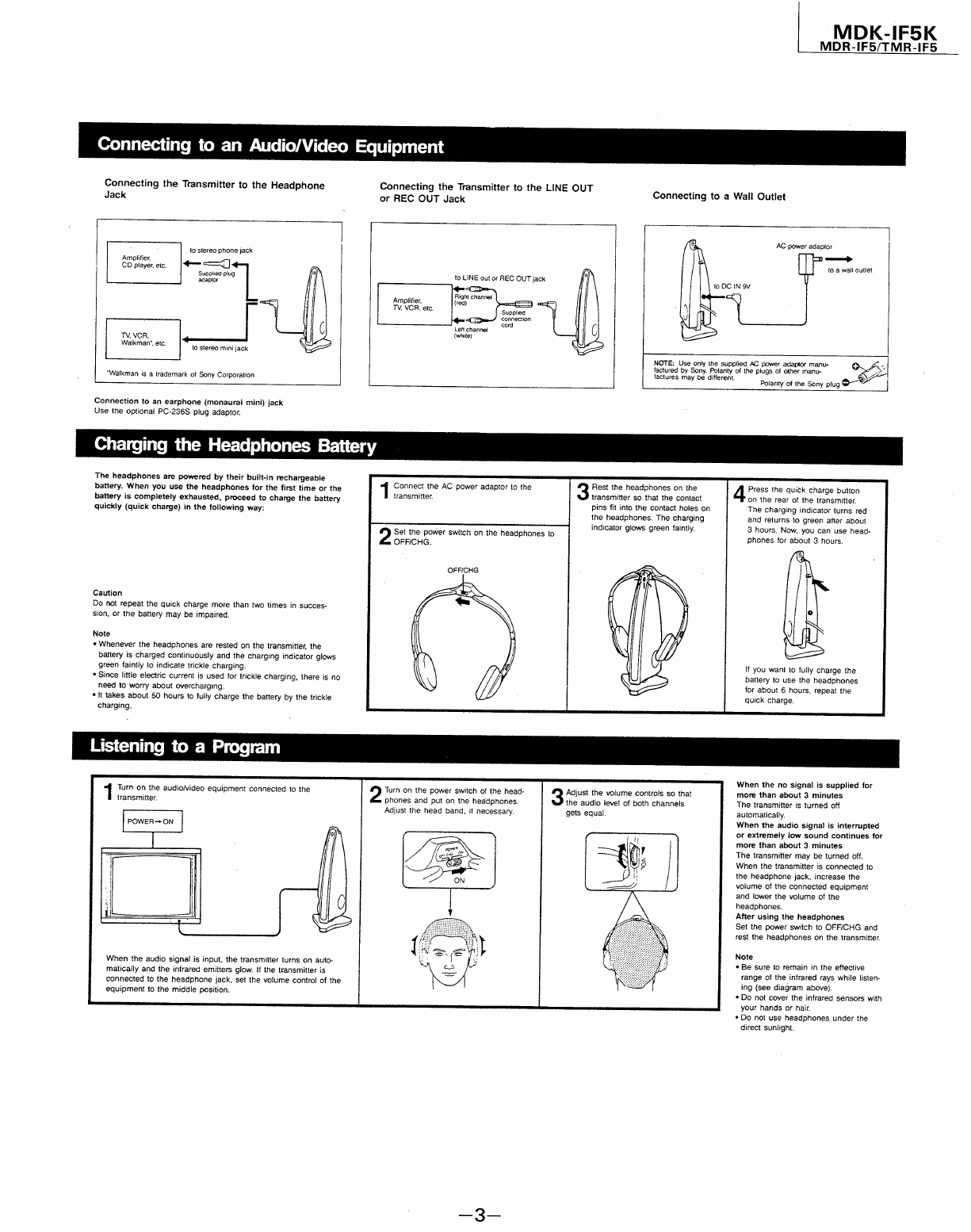
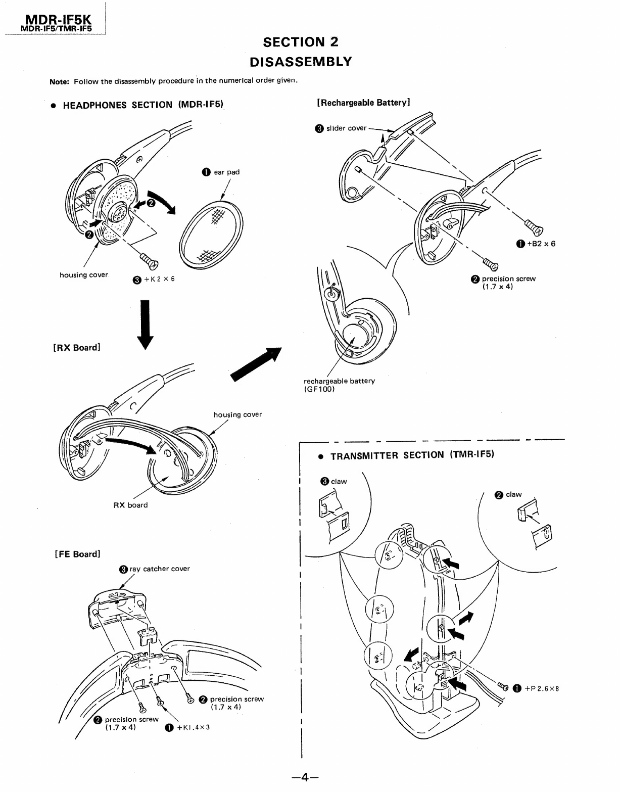
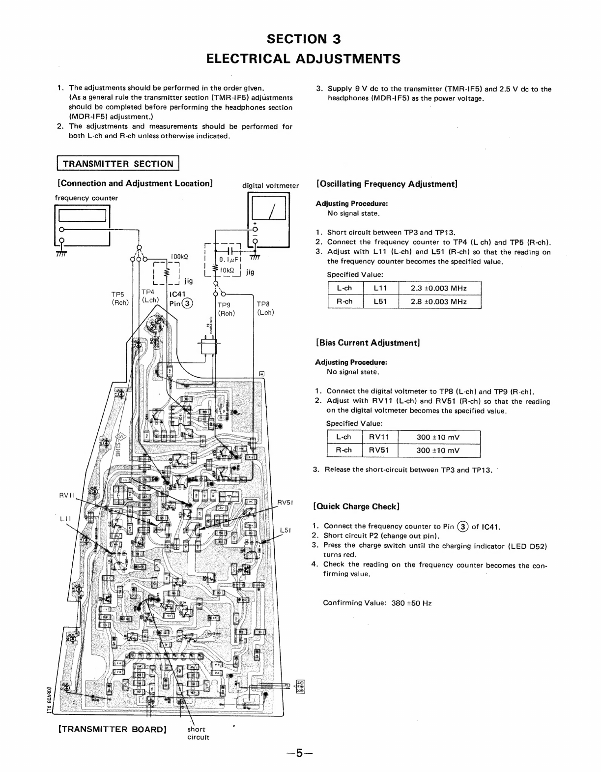
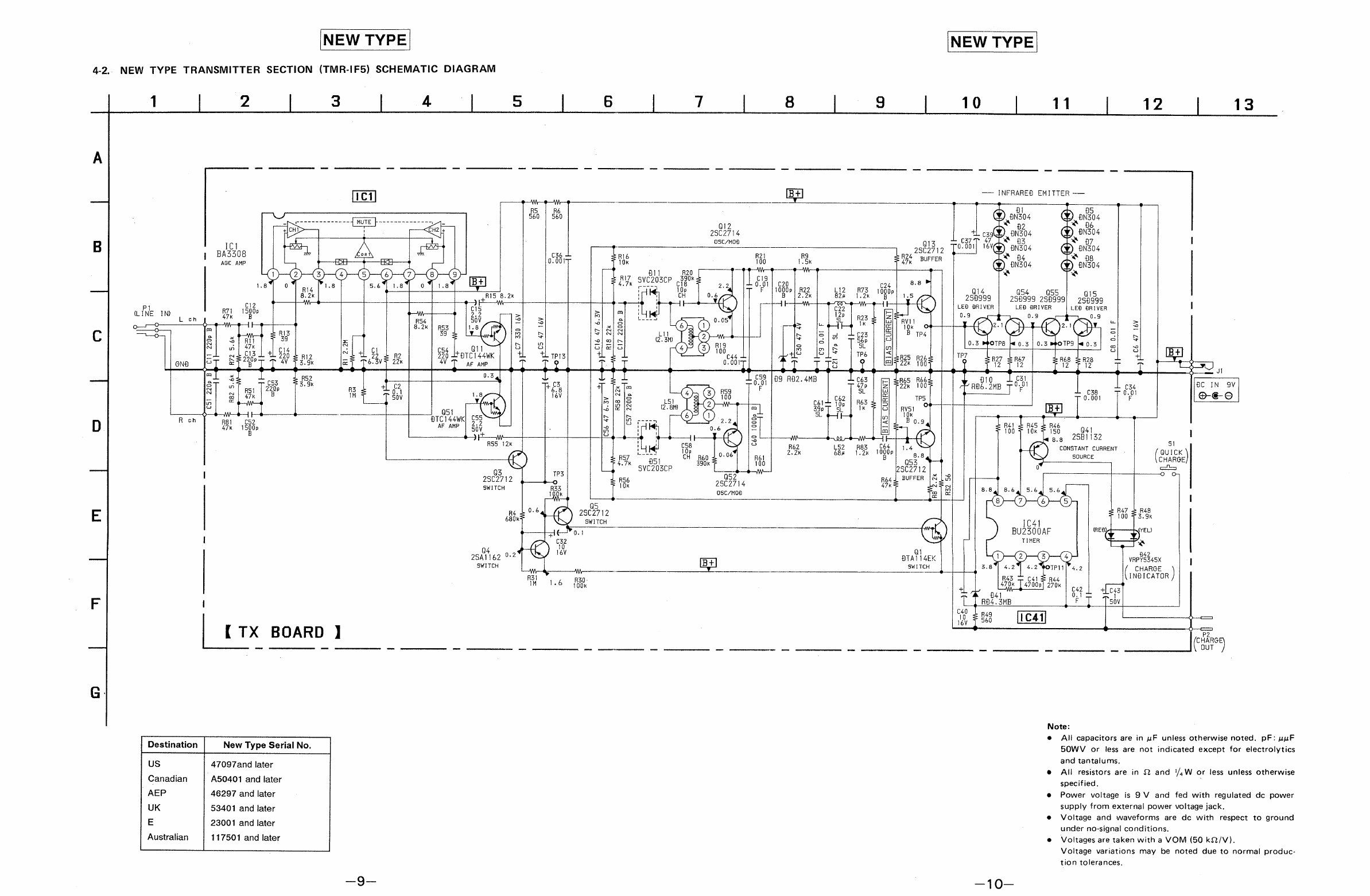
Sony MDR-IF5K User manual

US
Model
Canadian
Model
DRIES
MEP
Model
UK
Model
E
Model
Australian
Model
Discard
MDR-IF5K
Service
Manual
(No.
9-953-691-12)
priviously
issued.
This
Service
Manual
contains
it.
TMR-IF5
(Transmitter)
SPECIFICATIONS
General
Headphones
MDR-IF5
Infrared
wavelength:
850nm
Power
source:
Built-in
rechargeable
battery
(GF
100)
Moduiation:
Frequency
modulation
Weight:
98g
(3.5
02.)
Carrier
frequency:
Right
2.8
MHz
Left
2.3MHz
Supplied
accessories
Effective
range:
up
to
7m
(23
ft)
AC
power
adaptor
(1)
Frequency
response:
18
—
22,000
Hz
Connecting
cord
(stereo
mini
jack
—
stereo
phono
Distortion:
Less
than
1%
at
1
kHz
plugs)
(1)
.
Plug
adaptor
(stereo
mini
jack
—
stereo
phone
Transmitter
TMR-IF5
plug)
(1)
Power
source:
DC
9V
jack
accepts:
Screws
(M3.1
x
20mm)
(2)
Sony
AC-912
AC
power
Design
and
specifications
subject
to
change
adaptor
(supplied)
without
notice.
Dimensions:
88
x
220
x
93mm
(32
x
8%
x
33%
in),
(w/h/d)
Weight:
250
g
(8.8
02.)
Features
®
infrared
transmitting
system
eliminates
the
headphone
cord.
°
This
headphone
system
can
be
used
with
any
audio/video
equipment
provided
with
a
headphone
jack
or
line
out
jack.
°
The
quality
of
the
sound
is
excellent
because
it
is
transmitted
with
high
carrier
frequencies.
e
The
lightweight
rechargeable
battery
built
into
the
headphones
allows
a
compact
design
and
economical
operation.
®
A
trickle
charging
system
keeps
headphones
ready
to
use
whenever
they
are
rested
on the
transmitter.
e
You
can
adjust
the
audio
level
at
your
listening
position
by
using
the
volume
controls
on
the
headphones.
Ear
a
a
i
aa
eam
Sa
ee
Se)

MDK-IF5K
MDR-IF5/TMR-IF5
SECTION
1
GENERAL
Parts
fe
eyarti
icersit(eya|
Transmitter
3
Charging
indicator
Infrared
emitters
Power
indicator:
Infrared
sensors
Positioning
the
Transmitter
The
diagram
below
illustrates
the
approximate
effective
range
of
the
infrared
rays
emitted
from
the
transmitter.
Position
the
transmit-
ter
so
that
your
listening
area
is
within
the
effective
range.
The
infrared
rays
will
not
penetrate
walis
or
opaque
glass,
therefore
the
head-
phones
must
be
used
in
“in
sight”
area
of
the
transmitter.
SAFETY-RELATED
COMPONENT
WARNING!!
COMPONENTS
IDENTIFIED
BY
MARK
A
OR
DOTTED
LINE
WITH
MARK
A
ON
THE
SCHEMATIC
DIAGRAMS
AND
IN
THE
PARTS
LIST
ARE
CRITICAL
TO
SAFE
OPERATION.
REPLACE
THESE
COMPONENTS
WITH
SONY
PARTS
WHOSE
PART
NUMBERS
APPEAR
AS
SHOWN
IN
THIS
MANUAL
OR
IN
SUPPLEMENTS
PUB-
LISHED
BY
SONY.
Contact
pins
Quick
charge
button
DC
IN
9V
(DC
external
power
input)
jack
Audio
input
cord
-
infrared
sensor
Power
switch
Head
band
Contact
holes
Volume
controls
Ear
pads
ATTENTION
AU
COMPOSANT
AYANT
RAPPORT
A
LA
SECURITE!
LES
COMPOSANTS
IDENTIFIES
PAR
UNE
MARQUE
/\
SUR
LES
DIAGRAMMES
SCHEMATIQUES
ET
LA
LISTE
DES
PIECES
SONT
CRITIQUES
POUR
LA
SECURITE
DE
FONCTIONNEMENT.
NE
REMPLACER
CES
COM-
POSANTS
QUE
PAR
DES
PIECES
SONY
DONT
LES
NUMEROS
SONT
DONNES
DANS
CE
MANUEL
OU
DANS
LES
SUPPLEMENTS
PUBLIES
PAR
SONY.

MDK-IF5K
MDR-IF5/TMR-IF5
Connecting
to
an
Audio/Video
Equipment
Connecting
the
Transmitter
to
the
Headphone
Connecting
the
Transmitter
to
the
LINE
OUT
Jack
or
REC
OUT
Jack
_
|
[
Connecting
to
a
Wall
Outlet
AC
power
adaptor
—
to
a
wail
outlet
to
stereo
phone
jack
Amplifier,
CO
player,
ete.
<7]
Suoptied
plug
adaptor
to
LINE
out
or
REC
OUT
jack
ag
Right
ch:
Amplifier,
(res)
ohannet
TV.
VCR,
ete.
Supplied
connection
7
cord
Left
channet
TV.
VCR
(whnte)
Walkman’,
etc.
to
stereo
mini
jack
NOTE:
Use
only
the
supplied
AC
power
adaptor
manu-
factured
by
Sony.
Polarity
of
the
plugs
of
other
manu-
eo
.
.
.
factures
may
be
different.
j
Walkman
is
a
trademark
of
Sony
Corporation
y
|
Polarity
of
the
Sony
plug
Connection
to
an
earphone
(monaural
mini)
jack
Use
the
optional
PC-236S
plug
adaptor.
Charging
the
Headphones
Battery
The
headphones
are
powered
by
their
built-in
rechargeabie
a
battery.
When
you
use
the
headphones
for
the
first
time
or
the
Connect
the
AC
power
adaptor
to
the
Rest
the
headphones
on
the
Press
the
quick
charge
button
battery
is
completely
exhausted,
proceed
to
charge
the
battery
transmitter.
wens
ne
that
the
contac
‘on
th
ine
rear
of
the
transmitter.
quickly
(quick
charge)
in
the
following
way:
Pins
fit
into
the
conta
es
he
charging
indicator
turns
red
the
headphones.
The
charging
and
returns
to
green
after
about
indicator
glows
green
faintly.
3
hours.
Now,
you
can
use
head-
Set
the
power
switch
on
the
headphones
to
phones
for
about
3
hours.
OFFICHG.
OFFICHG
Caution
Do
not
repeat
the
quick
charge
more
than
two
times
in
succes-
sion,
or
the
battery
may
be
impaired.
Note
«
Whenever
the
headphones
are
rested
on
the
transmitter,
the
battery
is
charged
continuously
and
the
charging
indicator
glows
green
faintly
to
indicate
trickle
charging.
ft
'f
you
want
to
fully
charge
the
*
Since
little
electric
current
is
used
for
trickle
charging,
there
is
no
d
o
battery
to
use
the
headphones
need
to
worry
about
overcharging.
for
about
6
hours,
repeat
the
«lt
takes
about
50
hours
to
fully
charge
the
battery
by
the
trickle
;
quick
charge.
charging.
Listening
to
a
Program
When
the
no
signal
is
supplied
for
Turn
on
the
audio/video
equipment
connected
to
the
Turn
on
the
power
switch
of
the
head-
Adjust
the
volume
controls
so
that
more
than
about
3
minutes
transmitter.
phones
and
put
on
the
headphones.
the
audio
jevel
of
both
channels
The
transmitter
is
turned
off
Adjust
the
head
band,
if
necessary.
gets
equal.
automatically.
POWER—
ON
When
the
audio
signal
is
interrupted
4
-
or
extremely
low
sound
continues
tor
more
than
about
3
minutes
The
transmitter
may
be
turned
off.
When
the
transmitter
is
connected
to
the
headphone
jack,
increase
the
volume
of
the
connected
equipment
and
tower
the
volume
of
the
headphones.
After
using
the
headphones
Set
the
power
switch
to
OFF/CHG
and
rest
the
headphones
on
the
transmitter.
E :
Note
When
the
audio
signal
is
input,
the
transmitter
turns
on
auto-
_
3
;
¢
Be
sure
to
remain
in
the
effective
matically
and
the
infrared
emitters
glow.
If
the
transmitter
is
range
of
the
infrared
rays
while
listen-
connected
to
the
headphone
jack,
set
the
volume
contro!
of
the
ing
(see
diagram
above).
equipment
to
the
middle
position.
¢
Do
not
cover
the
infrared
sensors
with
your
hands
or
hair.
Do
not
use
headphones
under
the
direct
sunlight.

MDR-IF5K
MDR-IF5/TMR-IF5
|
SECTION
2
DISASSEMBLY
Note:
Follow
the
disassembly
procedure
in
the
numerical
order
given.
-@
HEADPHONES
SECTION
(MDR-IF5)
@
ear
pad
housing
cover
RX
board
[FE
Board]
@
ray
catcher
cover
@
precision
screw
x
(1.7
x
4)
@
precision
screw
(1.7
x
4)
@
+K1.4x3
[Rechargeable
Battery]
@
slider
cover
Y,
.
@
+82x6
@
precision
screw
(1.7
x
4)

SECTION
3
ELECTRICAL
ADJUSTMENTS
1.
The
adjustments
should
be
performed
in
the
order
given.
3.
Supply
9
V
dc
to
the
transmitter
(TMR-IF5)
and
2.5
V
dc
to
the
(As
a
general
rule
the
transmitter
section
(TMR-IF5)
adjustments
headphones
(MDR-IF5)
as
the
power
voltage.
should
be
completed
before
performing
the
headphones
section
(MDR-IF5S)
adjustment.)
2.
The
adjustments
and
measurements
should
be
performed
for
both
L-ch
and
R-ch
unless
otherwise
indicated.
TRANSMITTER
SECTION
[Connection
and
Adjustment
Location]
digital
voltmeter
[Oscillating
Frequency
Adjustment]
Adjusting
Procedure:
No
signal
state.
frequency
counter.
1.
Short
circuit
between
TP3
and
TP13.
2.
Connect
the
frequency
counter
to
TP4
(L
ch)
and
TP5
(R-ch).
3.
Adjust
with
L11
(L-ch)
and L51
(R-ch)
so
that
the
reading
on
the
frequency
counter
becomes
the
specified
value.
Specified
Value:
2.3
+0.003
MHz
2.8
40.003
MHz
TP8
(Leh)
[Bias
Current
Adjustment]
Adjusting
Procedure:
No
signal
state.
.
Connect
the
digital
voltmeter
to
TPS
(L-ch)
and
TPQ
(R-ch).
2.
Adjust
with
RV11
(L-ch)
and
RV51
(R-ch)
so
that
the
reading
on
the
digital
voltmeter
becomes
the
specified
value.
-_
Specified
Value:
3.
Release
the
short-circuit
between
TP3
and
TP13.
©
ae
[Quick
Charge
Check]
1.
Connect
the
frequency
counter
to
Pin
(3)
of
IC41.
.
Short
circuit
P2
(change
out
pin).
3.
Press
the
charge
switch
until
the
charging
indicator
(LED
D52)
turns
red.
4.
Check
the
reading
on
the
frequency
counter
becomes
the
con-
firming
value.
nN
Confirming
Value:
380
+50
Hz
{TX
BOARD]
(TRANSMITTER
BOARD)
short
circuit

regulated
dc
power
supply
HEADPHONES
SECTION
Note:
1.
On
adjusting
the
headphones
section
(MDR-IFS5),
use
the
trans-
mitter
(TMR-IF15)
as
a
jig.
2.
The
patterns
of
the
printed
circuit
boards
for
L-ch
and
R-ch
are
common.
3.
L-ch
adjustment
should
be
completed
before
performing
R-ch
adjustment.
[Preparation]
AF
OSC
€)
attenuator
O
_—_—_—_—_—
\\
input
plug
1
kHz
225
mV
1.
Feed
a
signal
to
jig
(TMR-IF5)
and
connect
a
power
supply
to
DC
IN
jack.
[Receiving
Frequency
Adjustment]
Adjusting
Procedure:
1.
Short
circuit
between
TP2
and
TP3.
2.
Turn
on
the
POWER
switch
of
the
headphones.
3.
Adjust
with
CT11
(L-ch)
and
CT51
(R-ch)
so
that
the
reading
on
VTVM
becomes
maximum.
[Gain
Adjustment]
(Former
Type
Only)
Adjusting
Procedure:
1.
Adjust
to
make
the
input
level
of
jig
(TMR-IF5)
as
low
as
possible.
2.
Adjust
with
CT12
(L-ch)
and
CT52
(R-ch)
so
that
the
reading
on
VTVM
becomes
maximum.
3.
Release
the
short-circuit
between
TP2
and
TP3.
[Connection
and
Adjustment
Location]
FORMER
TYPE
CT12
(L-ch)
CT52
(R-ch)
CTI!
(Lech)
CT5I
(Roh)
VTVM
(RX
Leh/RX
Rch
BOARD]
[Filter
Character
Adjustment]
(New
Type
Only)
Setting:
AM
rf
signal
generator
No
modulation
GND
2.8
MHz
(Lch)
2.3
MHz
(Rch)
output
level:
100
mV
(100
dB)
_
Adjustment
Procedure:
1.
Input
to
TP6
of
Lch.
(2.8
MHz)
2.
Adjust
L53
of
Rech
so
that
the
reading
on
VTVM
becomes
minimum.
3.
Input
to
TP6
of
Rech.
(2.3
MHz)
4.
Adjust
L13
of
Lch
so
that
the
reading
on
VTVM
becomes
minimum.
[Connection
and
Adjustment
Location]
NEW
TYPE
L13
(Leh)
L53
(Rech)
short
circuit
CT11
(Leh)
CT51
(Rech)
regulated
dc
power
supply
2.5
V
de
[RX
Lch/RX
Rch
BOARD]

NEW
TYPE
NEW
TYPE
SECTION
4
DIAGRAMS
NEW
TYPE
TRANSMITTER
SECTION
(TMR-IF5)
PRINTED
WIRING
BOARD
4-1.
13
12
11
[TX
BOARD]
Cc
he
2
2
8
5s
|S
os
ec
O06].
CPE
5
8
|
O1w;e
°
ra
P2
(CHARGE
OUT)
Bp
pene
aynvanenaneanwnienpennnananneet
£
;
fete
"
3
i
i
:
:
Gee
t
2
A
PI
(LINE
IN)
i
New
Type
Serial
No.
Destination
@®
Semiconductor
Lead
Layouts
VPRY5345X
DN304A
47097and
later
A50401
and
later
Canadian
46297
and
later
.
53401
and
later
‘|
23001
and
later
117501
and
later
Australian
Note:
Sg
a
3
~
|
oe
3
ae
=
[o)
a
2
Ee
89
oO
0
o
oo
Bi
craps
oy
~~
££.
6
96
}
ee
ee
coe]
o
®
re
oOo
Oo
o
|
a
we
x
x
o
oo
nn
wn
re
ee
os
oO
aa
e@
@
1.
ANODE
YEL
2.
CATHODE
3.
ANODE
RED

4-2.
NEW
TYPE
TRANSMITTER
SECTION
(TMR-I1F5)
SCHEMATIC
DIAGRAM
Pi
(LINE
IN)
ch
O
O
©
——_o-——
fo)
O
8
Es
N
tn
=
~
CX
a
:
O
a
x
a
oO
aq
w
N
N
a
n
fo
a
o
Roch
R81
47k
1
2
3
IC
|
BA3308
AGC
AMP
{
TX
BOARD
]
Destination
New
Type
Serial
No.
47097and
later
-A50401
and
later
46297
and
later
53401
and
later
23001
and
later
117501
and
later
US
Canadian
AEP
UK
E
Australian
Qi2
2802714
OSC/MOB
C54
399
tp
4V
m9
S
CQ
z
~
Lil
i
SN
ney
+
Qit
a)
%
TC144WK
2
¢
8
AF
AMP
T
aa
on
D9
RO2.
4MB
+
£3,
4]
T=
Tm
F
Me,
16V
“|e
(4)s
(3)
Rea
>
-
m/e
ls
Lol
=
(2)
.
i
6
2
|S
(2-em
1
g
al
o5g
=|
|B
CP
O,,)
Ig
2.2
oie
1
.
S
cov
2
id
be
0.6
=|
+
QO
J
H
()
o
RSS
12k
yo
C58
Y/
13
! i
10.
(V7
Roy
CH
Rog
3
9°96
|
47
251
0
-
oO)
“
syczo3cp
890k
‘0
25C2712
Q5Z
aw
Rip6
2502714
OSc/MO8
Q5
R4
2902712
680k
SWITCH
|
Q4
2SA1162
0-2
SWITCH
R31
a
OO
—
mM
1.6
ASO
C3
0.01
F
C21
479
SL
wo
oo-
Ton
10
1
1
12 13
—-
INFRARE®
EMITTER
——
DI
@)
an304
@)
an304
92
.
+L
cxoQ)AN304
Y),
BNS04
'
Q13
23c2712
TOPO!)
TY)
anso4
Y)
BN504
R24
BUFFER
“3
47K
()
8N304
Y)
8N304
ne
‘
*
1000
°
Qi4 Q54
ass
i]
B
259999
|
258999
2586991
pdcdq
14
LED
ORIVER
LED
BRIVER
LE®
BRIVER
I
BIAS
CURRENT
BIAS
CURRENT
0.9
(?
>
0.9
{?
Ne
jo
210
icy
- 3
CO)
eV
TR’
eV)
sf
fo)
+
OTP8
0.3}
0.3
OTPS
0.3
“|
S|
Ba
f25
926
fi
R27
=
R67
R68
=R28
+
¢
.
100
12 12 12 12
=
r
>
R65
Rb6
BIO
C31
ial
00
RBS.
2MB
70.0!
034
BC
IN
9V
C38
FOOT
TP5
0-001
F
©-€-O
—9—
R41
&
RAS
&
R46
=
400
=
10x
=
150
Q41
|
sg
2981132
«1
()
CONSTANT
CURRENT
QUICK
aN
SOURCE
(SyicK
0
ott
O
O
I
47
&
R48
00
=
3.
9k
a
C22
Tore
Qt
B42
BTATtI4EK
VRPY5345X
|
SWITCH
CHARGE
INDICATOR
+
C40
10
O-——
©
—
A
A
SF
ST
A
ST
I
HE
|
NOISES
|
GU
|
UNASUETETGEEMSENUN
OSI
Note:
All
capacitors
are
in
wF
unless
otherwise
noted.
pF:
uuF
50WV
or
tess
are
not
indicated
except
for
electrolytics
and
tantalums,
All
resistors
are
in
9
and
1/,W
or
less
unless
otherwise
specified.
Power
voltage
is
9
V
and
fed
with
regulated
dc
power
supply
from
external
power
voltage
jack.
Voltage
and
waveforms
are
dc
with
respect
to
ground
under
no-signal
conditions.
Voltages
are
taken
with
a
VOM
(50
kQ2/V).
Voltage
variations
may
be
noted
due
to
normal
produc-
tion
tolerances.

4-3.
NEW
TYPE
HEADPHONES
SECTION
(MDR-IF5)
PRINTED
WIRING
BOARDS
NEW
TYPE
|
NEW
TYPE
a
a
ee ee
Ee
5
|
6
|
+
|
6
|
9
[|
[|
7%
3
Gan
r»
e
Semiconductor
A
|
(POWER)
;
Location
D1
B-7
Note:
go
The
ON
=®
OFF/CHARGE
©
@
o—-:
parts
extracted
from
the
component
side.
‘a
*
6
ca
—
ae
©
#—:
parts
extracted
from
the
conductor
side.
e
Solder
the
yellow
lead
to
the
red
marked
terminal
on
each
SP11
and
SP51.
Destination
New
Type
Serial
No.
US
47097and
later
Canadian
A50401
and
later
AEP
46297
and
later
UK
53401
and
later
E
23001
and
later
Australian
117501
and
later
TO
SHIELD
235
6H
Ee
ee
|
DI:
INFRARED
|
aa
|
|
SENSOR
Ly
|
|
06:
POWER
|
RED
|
INDICATOR
|
Gi.
OF
e
as
——————p
{Lt
_—___-
©
>
a
®
BATT2
®
=
BATT
|
BATTERY
Cae)
(
NI-
CD
)
[RX(R)
BOARD]
|
—
~f
(RX
(L)
BOARD]
|
®
[FE
BOARD]
W
(CONDUCTOR
SIDE)
|
"7
e
*
i
fs
ial
\
i
\
44
bi
om
m
A
\
ALI
a
‘|
;
‘
:
D3
D2
y
AAW
eee
aie
|
(4)
Cees)
Yh
‘S
i.
yt.
SENSOR
f
St
.
ANAS
:
:
|
OST
/
\
Sa
BRN
|
Spa
AQ
=
:
i
BLU
35]
BRN
2k’
BLK
I
lo}
—
RVSI
Seat
——
@
Semiconductor
Lead
Layouts
CXA1280N
PP506-1
PP601-1
TLR226
(Top
view)
cathode
anode
—11—
—12—
anode

4-4.
NEW
TYPE
HEADPHONES
SECTION
(MDR-IF5)
SCHEMATIC
DIAGRAM
1
2 3
4
r=)
6
7
8
g
RI
2.2k
Bl
PPS06-1
(INFRARED
SENSOR)
10
O
O
RV11
SOk
11
12
13
(vou
mn
TGA
CXA1280N
FE/BDET/POWER
Q2
28€2712
RF
AMP
Qt
25K209
RF
AMP
|
TO
SHIELD
PAPER
@
~~
82
PP601-1
(INFRARED
SENSOR)
a
eee
IE
|
I
ee
eee
Lal
BATT
(RATTERY)
NI-C8
£3
PP601-1
(INFRARE®
SENSOR)
I
“a
as
a
|
C16
150p
SL
Qit
2502712
[B+]
BAND
PASS
RVS1
50k
£51
HSM276S
[vot]
1
TP7
C59
[+
-01
10
o
Lol
+C52
TX]
FO
YQ
4yV
5
1007
509
i¥}
BATT2
C58
0.01
F
Q13
BICTI4YK
ia
[
RX
(L)
BOARD]
|
CFS1
(2/2)
C67
‘Gn
3p
—
et
Saf
3
—
52
50
(aE)
NI-CB
[
EF
(CHARGE
IN)
Note:
H
'@
All
capacitors
are
in
wF
unless
otherwise
noted.
pF:
uwuF
5OWV
or
less
are
not
indicated
except
for
electrolytics
and
tantalums,
e
All
resistors
are
in
Q
and
1¥/,W
or
less
unless
otherwise
specified.
e@
Power
voltage
is
dc
2.5
V
and
fed
with
regulated
dc
power
supply
from
BATT
TERMINAL.
AEP
Voltage
and
waveforms
are
dc
with
respect
to
ground
UK
under
no-signal
conditions.
e@
Voltages
are
taken
with
a
VOM
(50
kQ/V).
E
Voltage
variations
may
be
noted
due
to
normal
produc-
Australian
tion
tolerances.
Destination
US
Canadian
CXA1280N
FE/DET/POWER
New
Type
Serial
No.
47097and
later
A50401
and
later
46297
and
later
53401
and
later
23001
and
later
@51
25C2712
BAND PASS
Q53
BICI14YK
SWITCH
117501
and
fater

FORMER
TYPE
FORMER
TYPE
4-5,
FORMER
TYPE
TRANSMITTER
SECTION
(TMR-IF5)
PRINTED
WIRING
BOARD
a
ee
ee
a
es:
9
AO
Ns
I
[TX
BOARD]
ene
scen,
Leto
(Peter
mnpeyy
ii
oan
(ae
Ke
yt
DoE
mans
Sy
GUL
ae
m
nt
INR
RARED
EMITTER
mom
ios
a,
4
nS
i
Hl
é
if
Z:
ett
ipntoepnewensesoonaosaeacaubatereeacintoccanqnenpvenvenaseanieciynton
aeRO
:
Parag,
Ee)
Gee
",
po
|
:
|
E
|
|
4
ne
fk
¥
vovnemaeann
NDICATOR)
Ko
(LINE,
IN)
@
Semiconductor
Location
Ret.
No.
|
No.
[Location
|
F
B-7
BS
B-9
C-1
C-1
C-6
E-6
ll
De
D9
G
y
Fe
F-6
Jl
DC
IN
9V
;
a
-10
.
:
Semiconductor
Lead
Layouts
Destination
|
Former
Type
Serial
No.
DN304A
VPRY5345X
US
Up
to
47096
Note:
Canadian
Up
to
A50400
®
oO——:
parts
extracted
from
the
component
side.
@
@—:
parts
extracted
from
the
conductor
side.
AEP
Up
to
46296
E.
«
Up
to
23000
jo)
Vo
3
4.
ANODE
YEL
2.
CATHODE
3.
ANODE
RED
mmMmOTOQODUUBOUDON
OO
odmuNKoeobuNhagaa
—15—
a
hy

[FORMER
TYPE,
_
|FORMER
TYPE)
4-6.
FORMER
TYPE
TRANSMITTER
SECTION
(TMR-IF5)
SCHEMATIC
DIAGRAM
1
,
3
4
ts)
6
7
8
9g
10
11
12
13
—
INFRARED
EMITTER
—
Y).
anos
©).
ONs04
Q12
6
28C2714
®,
ONS
@,
ON304
B
_
OSC/MOD
Qiz
o
aes
7
I
yd)
a
a
:
2802712
D
i
©.
aan
;
BUFFER
|
0.001T
10k
a
F
100
1.5k
47k
oP
ea
(¥)
DN304
©.
phen
4
20
=
1A
RL
IR
svezosce
gt
]
a
:
Q14
Q54 ass
H
7
C
‘e
82
250993 258999
25999
2anseg
FI
Cis
ae
:
0.4
C22
LE®
BRIVER
LE®
ORIVER
LE®
DRIVER
|
(LINE-
IN)
me
y
2,2
Pe
nog.
ml]
|
Se
[2p
0.9
0
4
-
ef
+----
1
=
O
2
Y
8.2k
|
RSZ
1.8
2
=
Oho
S
,
> a
NY)
\
NY
te
3
C
O
ah
ts
39
(olf?)
i
os
ea
ESTES)
Lu
Sl
i
isl.
CP
oO)
ey
=
ee
S
<o
=
XN
~o]
of
in
(2.
3M)
o=
st
ei
OC
3
ey
A}
a
C1
C54
Qit
5S}
8
SO},
G
B)
IB
lals
-
8; 38
B+]
ct
9
R12
Ve
th
22
5
pe
220
ATC144WK
+L
tL
qpy3
+L
48
jais
a
8
BT
GND
o
&
3.9k
=
6.3V
7
22k
AV
AF
AMP
T
oO
x
TN
Re?
Res
he
T
T
m=
=s
A
w
O
al
3
ns?
on
ie
TT
——
&T
4
3.9K
Pare
ts
gee
AC
IN
9V
S]oow
as
0.1
10
Nya
z|
2
SOV
Vaal
o
2
le
|S
GeO
Ee
Ct
ai
R
ch
DICTA
sWK
655
g
in
D
AF
AMP
|
258
~
a
Q4)
‘.
8
|
RSS
6.
8k
eae
re
E
:
RRENT
KC)
Ry
05
4
(auiex)
4.7K
|
03
13
=
252712
tl
28C2712
R56
R644
BUFFER
|&
gwitcd
f°
10k
2502714
47k
i
osc/4oa
‘0
;
0.6
Q5
E
R4
$
32
(”)
28€2712
rg
Bade
I
ES
SWITCH
,
Cov
;
0.1
Ts)
yy
r@
0.2%
Ve
2SA1
162
STAT
4E
85
SWITCH
K
VRPYS345X
I
SWITCH
CHARGE
RBI
‘
(inoteetor
)
eo
eee
ot
F
I
[TX
BOARD
]
)
“Fao
OUT
eee
aed
TN
—
—
Se
Former
Type
Serial
No.
US
Up
to
47096
Canadian
Up
to
A50400
AEP
Up
to
46296
Note:
E
Up
to
23000
@
All
capacitors
are
in
wF
unless
otherwise
noted.
pF:
MMF
5OWV
or
less
are
not
indicated
except
for
electrolytics
and
tantalums.
e
All
resistors
are
in
2
and
'/,W
or
less
unless
otherwise
specified.
e@
Power
voltage
is
9V
and
fed
with
regulated
dc
power
supply
from
external
power
voltage
jack.
e
Voltage
and
waveforms
are
dc
with
respect
to
ground
under
no-signal
conditions.
.
@
Voltages
are
taken
with
a
VOM
(50
kQ/V).
Voltage
variations
may
be
noted
due
to
normal
produc-
tion
tolerances.
aig
age

4-7.
FORMER
TYPE
HEADPHONES
SECTION
(MDR-IF5)
PRINTED
WIRING
BOARDS
FORMER
TYPE
ro
a
@
Semiconductor
Lead
Layouts
CXA1280N
PP506-1
TLR226
(Top
wew)
cathode
enode
anode
_
1
9
a
pias
uals
(COMPONENT
SIDE)
%
SI
f
{
POWER
)
Note:
ON
=>
OFF/CHARGE
@
o——:
parts
extracted
from
the
component
side.
ae
©
e—:
parts
extracted
from
the
conductor
side.
e®
Solder
the
yellow
lead
to
the
red
marked
terminal
on
each
ie
SP11
and
SP51.
|
TO
|
SHIELD
B
|
|
|
|
|
dk
|
:
1
4
|
|
,
i
|
|
06:
POWER
|
|
|
RED
|
|
INDICATOR
|
,
C
iS)
GRY
As
io
1.
5
6
GRY
©
(a
ay
=
res
@
2
z
BATT
|
BATT2.
©
|
(7
)
(38)
7
1.
{RX(R)
BOARD]
a
=
|
|__|.
_®
[FE
BOARD]
[]
(RX
(L)
BOARD]
SS
(CONDUCTOR
SIDE)
F
D
al
(nee
(#,
qs
INFRARED
)
i
BLU
3fo
wll
BLK
;
BRN
2b”
=
2
BRN)
RV51
RVII
[vor]
[vou]
Eee
FORMER
TYPE
e
Semiconductor
Location
Destination
Former
Type
Serial
No.
D1
B-7
US
Up
to
47096
Up
to
A50400
AEP
Up
to
46296
E
Up
to
23000
Canadian
29024

FORMER
TYPE
HEADPHONES
SECTION
(MDR-IF5)
SCHEMATIC
DIAGRAM
1
2
3
4
27
188123
a
aa
So
|
ae
ar
as
a
:
FORMER
TYPE
10
11
[FORMER
TYPE|
rs)
6
7
8
g
12
13
TO
SHIELD
PAPER
AF
POWER
AMP
2
PP401~1
CINFRARE®
SENSOR)
a,
Ci
0.01
0
Gee
F
F
Q{
Q2
25K209
2802712
3
a
Saw
RF
AMP
RF
AMP
0
© ©
9
c14
BTA143XK
|
a
ax
i
- .
220
BAND
PAS
A
!
[POWER]
BATTERY
aS
(7
47
4y
'
OFF/CHARGE
«———~
ON
(irt5
)
Be
5
t)
perroncmesetes
ers
03
PP6O1-1
(—)
ha
,
(INFRARE®
SENSOR)
C16
150
SL
ASS
©
©
O
roa
°
Q11
28C2712
Q13
BIC1I4YK
rt
eS
i\.
V7
[B+]
BAN
PASS
SWITCH
[
RX
(L)
BOARD
}
Re,
S/
,
a
rf
ee
se
a
ee
ote
cee
R4
YE
ee
mee
470
VSP
StM
a
NS
gg
en
ae
tee
a
rs
(¥)
ere
CF51
(2/2)
_
id
(POWER
INDICATOR)
BATT2
199837
:
aft
BATTERY
J
fo
(ae
aie
(__
ere
[
EF
BOARD
]
aaa
04
152835
(CHARGE
IN)
Note:
@
All
capacitors
are
in
uF
unless
otherwise
noted.
pF:
uF
SOWV
or
less
are
not
indicated
except
for
electrolytics
and
tantalums,
@
All
resistors
are
in
Q
and
'/,W
or
less
unless
otherwise
specified.
:
@
Power
voitage
is
dc
2.5
V
and
fed
with
regulated
dc
power
supply
from
BATT
TERMINAL.
@
Voltage
and
waveforms
are
de
with
respect
to
ground
under
no-signal
conditions.
@
Voltages
are
taken
with
a
VOM
(50
kQ/V).
Voltage
variations
may
be
noted
due
to
normal
produc-
tion
tolerances.
AM
IF
SET
AGC
Yes
I)
Destination
Former
Type
Serial
No.
US
Up
to
47096
|
Canadian
Up
to
A50400
C56
150p
SL
AEP
Up
to
46296
Q51
2502712
Q53
ATC114YK
E
Up
to
23000
BAN®
PASS
SWITCH

NOTE:
The
mechanical
parts
with
no
reference
number
in
the
exploded
views
are
not
supplied.
The
construction
parts
of
an
assembled
part
are
indicated
with
a
collation
num-
ber
in
the
remark
column.
Items
marked
‘*"
are
not
stocked
since
they
are
seldom
required
for
routine
service.
Some
delay
should
be
antici-
pated
when
ordering
these
items.
(1)
TRANSMITTER
(TMR-IF5)
=z
°o
SAM
PWM
—
SECTION
5
EXPLODED
VIEWS
|
Due
to
standardization,
parts
with
part
number
suffix
-XX
and
-X
may
be
dif-
ferent
from
the
parts
specified
in
the
components
used
on
the
set.
Color
Indication
of
Appearance
-
Parts
Example:
(RED)
...KNOB,
BALANCE
(WHITE)
t
t
Cabinet's
Color
Parts’
Color
Part
No.
Description
7-685-134-19
SCREW
+P
2.6X8
3-319-288-01
FOOT
-
2-136-207-01
STAND
2-136-203-01
SHAFT,
STAND
2-136-202-01
SPRING
2-136-204-01
WINDOW
2-136-205-01
CABINET
(LEFT)
TYPE2
NON-SLIT
8
Remarks
No.
Part
No.
*2-136-239-01
9
7-621-255-40
10
2-136-206-01
1]
2-136-242-01
901
*A-4534-045-A
PI
1-574-552-11
P2
1-568-286-1]
Description
Remarks
LABEL,
MODEL
NUMBER
©
SCREW
+P
2X6
CABINET
(RIGHT)
BRACKET,
CABINET
MOUNTED
PCB,
TX
CORD
(WITH
PLUG)
PIN,
CONNECTOR

Part
No.
X-2136-201-1]
*
*3-563-500-01
2-136-241-01
2-136-245-01
2-136-211-01
2-136-218-01
2-136-229-01
2-136-240-01
3-703-272-1]
3-893-957-11]
2-136-223-01
2-136-209-01
3-815~-381-01
3-880-990—-00
2-136-219-01
7-685~-204-19
2-136-213-01
2-136-210-01
2-136-208-01
X-2136-202-1
2-136-228-01
Description
(2)
HEADPHONES
(MDR-IF5)
COVER
(LEFT)
ASSY,
SLIDER
SHEET
(S),
ADHESIVE
CLIP,
CORD
SPRING,
TENSION
PIN,
VR
FITTING
SPRING
SLIDER
(LEFT)
CUSHION,
HOUSING
SCREW
(1.7X4),
TAPPING
SCREW
(B
2X6),
P
TAPPING
COVER
(LEFT),
HOUSING
JOINTER,
CROSS
CUSHION,
ADJUSTMENT
SCREW
(1.7X3)
sFLAT,(+)
SPECIAL
HOUSING
SCREW
+KTP
2X6
TYPE2
NON-SLIT
HOLDER,
DRIVER
CUSHION,
URETHANE
PAD,
EAR
COVER
(RIGHT)
ASSY;
SLIDER
SLIDER
(RIGHT)
Remarks
No.
73
74
75
76
77
78
79
80
81
82
902
903
904
BATT]
BATT2
D2
D3
RVI]
RV51
~
SP11
SP51
—24—
Part
No.
2-136-220-01
2-136-224-01
2-136-221-01
2-136-214-01
2-136-212-01
2-136-215-01
7-627-451-28
*2-136-217-01
2-136-222-01
2-136-225-01
*A-4538-045-A
*A-4538-046-A
*A-4538-047-A
1-528-287-11
]-528-287-11
8-719-975-20
8-719-975-20
1-238-495-11
1-238-495-11
1-505-089-11
1-505-089-11
Description
:
7
a?
902
not
supplied
Remarks
COVER
(RIGHT),
HOUSING
GUIDE
(RIGHT),
CORD
CUSHION
(RIGHT),
HEAD
COVER
(UPPER),
RAY
CATCHER
KNOB,
SLIDE
COVER
(LOWER),
RAY
CATCHER
SCREW
PRECISION
+K
1.4X3
BAND,
HEAD
CUSHION
(LEFT),
HEAD
GUIDE
(LEFT),
CORD
MOUNTED
PCB,
FE
MOUNTED
PCB
(LEFT),
RX
MOUNTED
PCB
(RIGHT),
RX
BATTERY,
NI-CD
(GF100)
BATTERY,
NI-CD
(GF
100)
PHOTO
DIODE
PP601-1
PHOTO
DIODE
PP601-1
RES,
VAR,
CARBON
50K
(VOLUME)
(WITH
KNOB)
RES,
VAR,
CARBON
50K
(VOLUME)
(WITH
KNOB)
DRIVER
(023F015)
DRIVER
(023F015)

SECTION
6
ELECTRICAL
PARTS
LIST
NOTE:
e@
Due
to
standardization,
replacements
in
the
parts
list
may
be
different
from
the
parts
specified
in
the
diagrams
or
the
components
used
on
the
set.
@
Items
marked
“*”
are
not
stocked
since
they
are
seldom
required
for
routine
service.
Some
delay
should
be
anticipated
when
ordering
these
items.
e
lf
there
are
two
or
more
same
circuits
in
a
set
such
as
a
stereophonic
machine,
only
typical
circuit
parts
may
be
indicated
and
capacitors
and
resistors
in
other
same
circuits
may
be
omitted.
[TRANSMITTER
TMR-IF5]
Ref
.No.
Part
No.
Description
901
*A-4534-045-A
MOUNTED
PCB,
TX
Cl
1-124-778-00
ELECT
22MF
C2
-
A=120"187-11
“ELECT
0.1MF
C3
1-124-779-00
(FORMER)...ELECT
10MF
C3
Vel26-119-1))
(NEW)
a
eeaes
ELECT 6.8MF
c5
1-126-204-11
ELECT
47MF
C6
1-126-204-11
ELECT
47MF
C7
1-124-119-00
ELECT
330MF
C8
1-163-059-00
CERAMIC
CHIP
0.01MF
C9
1-163-059-00
CERAMIC
CHIP
0.01MF
C1]
1-163-189-GO.
CERAMIC
CHIP
220PF
Ci2
1-163-205-00
(FORMER)...CERAMIC
CHIP
0.001MF
C12.
1-163-209-00
(NEW)......CERAMIC
CHIP
0.001
SME
C13.
1-163-189-00
CERAMIC
CHIP
220PF
C14.
1-126-246-11
ELECT 220MF
C15:
1-126-195-11
ELECT
2.
OME
C16:
1-126-205-11_
ELECT
7ME
C17:
1-163-213-00
CERAMIC
CHIP
0.0022MF
C18:
1-163-157-00
CERAMIC
CHIP
10PF
C19:
1-163-059-00
CERAMIC
CHIP
0.01MF
C20
1-163-205-00
CERAMIC
CHIP
0.001MF
C21
1-163-173-00
CERAMIC
CHIP
47PF
C22:
1-163-159-00
CERAMIC
CHIP
12PF
C23.
1-163-175-00
CERAMIC
CHIP
56PF
C24
1-163-205-00
CERAMIC
CHIP
0.001MF
C30.
1-126-208-11
ELECT
47ME
C31
1-163-059-00
CERAMIC
CHIP
0.01ME
C32:
1-124-779-00
ELECT
1
OME
C34:
1-163-059-00
CERAMIC
CHIP
0.01MF
C36
—-1-163-205-00
CERAMIC
CHIP
0.001MF
C37:
1-163-205-00
CERAMIC
CHIP
0.001MF
C38.
-1-163-205-00
CERAMIC
CHIP
0.001MF
C39.
1-126-204-11
(NEW)...ELECT
|
47MF
C40:
1-124-779-00
(NEW)...ELECT
10MF
C41
1-163-055-00
CERAMIC
CHIP
0.0047MF
C42
1-163-077-00
CERAMIC
CHIP
0.1MF
C43
126-1
93-11.
“ELECT
IMF
c44
1-102-074-00
(NEW)...CERAMIC
0.001MF
C51
1-163-189-00
CERAMIC
CHIP
220PF
C52
1-163-205-00
(FORMER)...CERAMIC
CHIP
ve
0.001
MF
C52
1-163-209-00
(NEW)......CERAMIC
CHIP
,
0.001
SMF
C53
~163-189-00
CERAMIC
CHIP
220PF
c54
-126-246-11
ELECT
220MF
20%
20%
20%
20%
20%
20%
20%
10%
10%
10%
10%
20%
20%
20%
10%
5%
10%
5%
5%
5%
10%
20%
20%
10%
10%
10%
20%
20%
10%
20%
10%
10%
10%
10%
10%
20%
CAPACITORS:
MF:
pF,
PF:
uuF.
RESISTORS
e@
Allresistors
are
in
ohms.
@
F:
nonflammable
COILS
@
MMH:
mH,
UH:
wH
SEMICONDUCTORS
In
each
case,
U:
yw,
for
example:
UA...:
wA...,
UPA...:
uPA...,
UPC...:
uPC,
UPD...:
uPD...
Ref
.No.
Part
No.
C55:
1-126-195-11
C56
=:
1-126-205-11
6.3V
C57:
1-163-213-00
SOV
C58:
1-163-157-00
TOV
C59:
1-163-059-00
35V C60
1-163-205-00
C61
1-163-171-00
16V
16V
C62.
~=—s-
1-163-157-00
16V
C63.
~—s-
1-16
3-173-00
C64.
~—s-
1-163-205-00
50V
SOV
D1
8-719-975-2]
50V
D2
8-719-975-21
D3
8-7]
9-975-2]
50V
D4
8-719-975-21
D5
8-719-975-21
SOV
D6
8-719-975-21
D7
8-719-975-21
50V
4v D8
8-719-975-21
S0V
D9
8-719-105-28
10
8-719-106-08
6.3V
SOV
011
8-719-939-02
SOV
D41
8-719-105-64
D42
=:
8-719-975-26
SOV
D5]
8-719-939-02
50V
SOV
ICl
8-759-939-73
IC41
8-759-937-65
50V
SOV
J
1~-507-563-00
50V
JRI
1-216-296-00
av
JR2
1-216-296-00
SOV
JR3-1-216-296-00
16V
JR4——-
1-216
-296-00
SOV
JR5
—-
1-216-296-00
SOV
JR6
—-
1-216-296-00
50V
JR7
—-
1-216-296-00
S0V
JR8
=:
1-216-296-00
16V
JR9
—-1-216-296-00
16V
JRIO
1-216-296~00
SOV
Ll]:
1-406-333-11
5OV
L12.-1-408-788-21
L511
-406-334-11
SOV
L52
1-408-787-00
50V
SOV
P)
1-574-552-11
p2
1-568-286-11
SOV
QI
8-729-901
-04
Q3
8-729-271
-22
SOV
Q4
8-729-216-21
S50V
ay
The
components
identified
by
mark
or
dotted
line
with
mark
are
Critical
for
safety.
eplace
only
with
part
number
specified.
Les
composants
identifiés
par
une
|
marque
sont
critiques
pour
fa
sécurité.
Ne
les
remplacer
que
par
une
piéce
portant
le
numéro
spécifié.
Description
ELECT
2.2MF
20%
50V
ELECT
47MF
20%
6.3V
CERAMIC
CHIP
0.0022MF
10%
50V
CERAMIC
CHIP
10PF
5%
50V
CERAMIC
CHIP
0.01MF
50V
CERAMIC
CHIP
0.001MF
10%
~~
50V
CERAMIC
CHIP
39PF
5%
50V
CERAMIC
CHIP
10OPF
5%
50V
CERAMIC
CHIP
47PF
5%
50V
CERAMIC
CHIP
0.001MF
10%
SOV
DIODE
DN304A
DIODE
DN304A
DIODE
DN304A
DIODE
DN304A
DIODE
DN304A
DIODE
DN304A
DIODE
DN304A
DIODE
DN304A
DIODE
RD2.4M-B
DIODE
RD6.2M-B2
DIODE
SVC203CP
DIODE
RD4.3M-B2
DIODE
VRPY5345Xx
DIODE
SVC203CP
IC
BA3308
IC
BU2300AF
JACK,
DC
(DC
IN
9V)
METAL
GLAZE
0 a
1/8W
METAL
GLAZE
0
5%
1
/8W
METAL
GLAZE
0
5%
1/8W
METAL
GLAZE
0
5%
)
/8W
METAL
GLAZE
0
5%
1/8W
METAL
GLAZE
0
5%
1/8W
METAL
GLAZE
0
5%
1/8W
METAL
GLAZE
0
5%
1
/8W
METAL
GLAZE
0
5%
1/8W
METAL
GLAZE
0
5%
1/8W
COIL
(OSC)
INDUCTOR
CHIP
82UH
COIL
(OSC)
INDUCTOR
CHIP
68UH
CORD
(WITH
PLUG)
PIN,
CONNECTOR
TRANSISTOR
DTA114EK
TRANSISTOR
2SC27126
TRANSISTOR
2SA1162Y

Ref
.No.
Q5
Ql]
Ql2
Q13
Q14
Q15
04)
Q51
Q52
Q53
Q54
Q55
R]
R2
R3
R4
RS
R6
R8
RQ
R11
R12
R13
R14
R15
R15
R16
R17
R18
R19
R20
R21
R22
R23
R24
R25
R26
R27
R28
R30
R31
R32
R33
R4]
Part
No.
8-729-271
-22
8-729-901
-03
8-729~200~87
8-729~27)
-22
8-729-199-92
8-729-199-92
8-729-903-47
8-729-90]
-03
8-729-200-87
8-729-27)
-22
8-729-1.99-92
8-7129-199-92
1-216-278-00
1-216-230-00
]-216-270-00
1-216~266-00
1-216-192-00
1-216-192-00
1-216-206-00
1-216-202-00
1-21
6-238-00
1-216-212-00
1-216-164-00
1-216-220-00
1-216-214-00
1-216-220-00
]-216-222-00
]-216-214-00
1-216-230-00
1-216-174-00
1-216-260~-00
1-216-174-00
1-216-206-00
1-216-198-0900
1-216-238-00
1-216-230-00
1-216-174-00
]-216-152-00
1-216-152-00
1-216-246-00
1-216-270-00
1-216-168-00
1-216-246-00
1-216-174-00
TRANSISTOR
TRANSISTOR
TRANSISTOR
TRANSISTOR
TRANSISTOR
TRANSISTOR
TRANSISTOR
TRANSISTOR
TRANSISTOR
TRANSISTOR
TRANSISTOR
TRANSISTOR
METAL
METAL
METAL
GLAZE
GLAZE
GLAZE
METAL
METAL
METAL
GLAZE
GLAZE
GLAZE
METAL
METAL
METAL
GLAZE
GLAZE
GLAZE
METAL
METAL
METAL
GLAZE
GLAZE
GLAZE
(FORMER)...METAL
GLAZE
METAL
GLAZE
8.
(NEW)....6.
METAL
GLAZE
METAL
GLAZE
METAL
GLAZE
METAL
GLAZE
METAL
GLAZE
METAL.
GLAZE
GLAZE
GLAZE
GLAZE
METAL
METAL
METAL
METAL
GLAZE
METAL
GLAZE
METAL
GLAZE
METAL
METAL
METAL
GLAZE
GLAZE
GLAZE
(NEW)...
.MET
(NEW)...
.MET
METAL
GLAZE
Description
28027126
DTC144WK
280271
4Y
2$C2712G
2S0999
2SD999
28B1132
DTC144WK
280271
4Y
28C2712G
2SD999
2SD999
2.2M
22K
1M
~
680K
560
560
2.2K
1.5K
47K
3.9K
39
8.2K
10K
4.7K
22K
100
390K
100
2.2K
1K
ATK
22K
100
12
12
100K
1M
AL
AL
GLAZE
GLAZE
100
5%
of
fo
5%
5%
5%
5%
5%
5%
5%
5%
5%
5%
5%
5%
5%
5%
5%
5%
5%
5%
5%
56
100K
5%
—26—
Ref
.No.
R43
R44
R45
R46
R47
R48
R49
R51
R52
R53
R54
R55
1/8W
R55
1/8W
1/8W
R56
R57
1/8W
R58
1/8W
1/8W
R59
R60
1/8W
R61
1/8W
1/8W
R62
R63
1
/8W
R64
1/8W
1/8W
R65
R66
7K
5%
1/8W
R67
2K
5%
1/8W
R68
1/8W
R71
1/8W
R72
1
/8W
R73
1/8W
R81
1/8W
R82
1/8W
R83
1
/8W
RVT1
1
/8W
RV5}
1
/8W
$}
1
/8W
1/8W
1/8W
1/8W
1/8W
1/8W
5%
1/8W
5%
1/8W
1/8W
Part
No.
1~-216-262-00
1-216-256-00
1-216-222-00
1-216-178-00
1-216-174-00
1-276-212-00
1-216-192-00
1-216-238-00
1~216-212-00
1-216-164-00
1-216-220-00
1-216-218-00
1-216-224-00
1~216-222-00
1-2176-214~-00
1-216-230-00
1-216-174-00
1-216-260-00
1-216-174-00
1-216-206-00
1-216-198-00
1-216-238-00
1-216-230-00
1-216-174-00
1-216-152-00
1-216~152-00
1-216-238-00
]-216-216-00
1-216-200-00
1-216-238-00
1-216-216-00
1-216-200-00
1-230-870-11
1-230-870-11
1-553-976-00
5%
.
Description
METAL
GLAZE
470K
5%
METAL
GLAZE
270K
5%
METAL GLAZE
10K
5%
METAL GLAZE
150
METAL
GLAZE
100
5%
METAL
GLAZE
3.9K
5%
METAL
GLAZE
560
5%
METAL GLAZE
47K
5%
METAL GLAZE
3.9K
5%
METAL
GLAZE
39
5%
METAL
GLAZE
8.2K
5%
(FORMER)...METAL
GLAZE
(NEW)......
METAL
GLAZE
METAL
GLAZE
10K
5%
METAL
GLAZE
4.7K
5%
METAL GLAZE
22K
5%
METAL
GLAZE
100
5%
METAL
GLAZE
390K
5%
METAL GLAZE
100
5%
METAL
GLAZE
2.2K
5%
METAL
GLAZE
1K
5%
METAL
GLAZE
47K
5%
METAL
GLAZE
22K
5%
METAL
GLAZE
100
5%
METAL
GLAZE
12
5%
METAL GLAZE
12
5%
METAL
GLAZE
47K
5%
METAL
GLAZE
5.6K
5%
METAL GLAZE
1.2K
5%
METAL
GLAZE
47K
5%
METAL
GLAZE
5.6K
5%
METAL
GLAZE
1.2K
5%
1
/8W
1/8W
1
/8W
1/8W
1/8W
1/8W
1/8W
1/8W
1/8W
1
/8W
1/8W
6.8K
5%
12K
5%
1/8W
1/8W
1
/8W
1
/8W
1
/8W
1/8W
1/8W
1/8W
1/8W
1/8W
1/8W
1/8W
1/8W
1/8W
1/8W
1
/8W
1
/8W
1
/8W
1/8W
RES,
ADJ,
METAL
GLAZE
10K
RES,
ADJ,
METAL
GLAZE
10K
SWITCH,
PUSH
1
/8W
1/8W

[HEADPHONES
MDR-IF5]
Ref
.No.
902
903
904
BATT]
BATT2
Cl
C2
C3
c4
cs
C6
Cc?
C10
C11
C11
C12
C13
C14.
C15
C16
C17
.
Cl7
C18
C19
C20
C21
C22
C22
C23
C23
C24
C25
C26
C27
C28
C29
C30
C31
C32
C50
C5]
C52
Part
No.
.
*A-4538-045-A
*A~4538-046-A
*A~4538-047
-A
1-528-287-11
1-528-287-1]
1-164-232-11
]-135-180-2)
1-163-033-00
163-093-00
163-033-00
]
1-
1-
1-135-158-21
63-101
-00
1-163-121-00
1-163-121-00
1-163-038-00
1-163-077-00
1-164-232-71
1-135-157-21
1-164-234-7]
1-124-432-00
1-164-222-1)
1-164-234-11
1-164-222-1)
]-164-234-11
1-163-037-11
1-163-035-00
1-163-038-00
1-135-180-21
1
-135-180-21
1-163-038-00
4-433-00
4-222-11
5~151~21
1-12
1-16
1-13
63-122-00
63-021
-00
§
]-]
}-]
1~-163-104-00
Description
MOUNTED
PCB,
FE
MOUNTED
PCB
(LEFT),
MOUNTED
PCB
(RIGHT),
BATTERY,
NI-CD
BATTERY,
NI-CD
CERAMIC
CHIP
TANTAL.
CHIP
CERAMIC
CHIP
0.022MF
|
CERAMIC
CHIP
CERAMIC
CHIP
0.022MF
TANTAL.
CHIP
CERAMIC
CHIP
0.01ME
3.
3MF
10PE
1
5ME
6PF
10%
20%
10%
0.5PF
(NEW)...CERAMIC
CHIP
710PF
5%
(FORMER)...CERAMIC
CHIP
O.O1MF
.
(NEW)......
CERAMIC
CHIP
51PF
(NEW)......CERAMIC
CHIP
22PF
of
CERAMIC
CHIP
18PF
CERAMIC
CHIP
22PF
CERAMIC
CHIP
CERAMIC
CHIP
1
5O0PF
150PF
io
5%
of
fo
5%
(NEW).
.....
CERAMIC
CHIP
0.1MF
(FORMER)...CERAMIC
CHIP
0.1MF
CERAMIC
CHIP
TANTAL.
CHIP
CERAMIC
CHIP
ELECT
0.01
MF
1OMF
1MF
47MF
20%
20%
(FORMER)...CERAMIC
CHIP
0.22MF
(NEW)....0.
CERAMIC
CHIP
1MF
(NEW)......
CERAMIC
CHIP
0.22MF
(FORMER)...CERAMIC
CHIP
1MF
CERAMIC
CHIP
CERAMIC
CHIP
CERAMIC
CHIP
TANTAL.
CHIP
0
.022MF
0.047MF
O.1MF
3.3MF
10%
20%
TANTAL.
CHIP
3.3MF
CERAMIC
CHIP
0.1MF
20%
ELECT
1O0MF
CERAMIC
CHIP
0.22MF
(NEW)...TANTAL.
CHIP
4.7MF
20%
20%
(NEW)...CERAMIC
CHIP
160PF
CERAMIC
CHIP
0.01MF
(NEW)...CERAMIC
CHIP
30PF
50V
4y
‘OV
50V
50V
ay
SOV
50V
50V
5%
50V
5%
50V
50V
50V
SOV
50V
5OV
50V
50V
ay
10V
4y
25V
10V
25V
10V
25V
50V
25V
ay
25V
4y
25V
4y
SOV
SOV
Ref
No.
C53
C54
C55
C56
C57
C57
C58
C59
C60
C6]
C62
C62
C63
C63
c64
C65
C66
C67
C68
C69
C70
C7)
C72
CFT]
CF5]
CTT]
C111
cT12
CT51
CT51
CT52
DI
D2
03
D4
D5
D6
D?
D8
D1]
DS]
[cli
[C51
—27—
Part
No.
1-163-472-11
1-163-101-00
1
-163-121-00
]-163-121-00
1-163-038-00
1~163-077-00
1-164-232-1)
]-135-1
57-21
1-164-234-171
]
~124-432-00
1-164-222-11
|
1~164-234-1]
1~164-222~171
]-164~-234-11
1-163-037-11
1~163-035-00
1-163-038-00
6
1-135-180-21
1-135~180-21
1-163~-038-00
24-433-00
64-222-1]
35-151-2]
1-577~589-8)
1-577-589-81
1-1
1]
1-1
~-1-141-313-11
4-141
-322-11
1-741
-322-1]
1-747
-313-11
1-141
-322-11
1-14]
-322-11
-719-975~19
~719-975-20
-719-975-20
19-100-03
19~100-05
19-81
2-26
9-918-88
9-91
8-88
9~918-88
9-918-88
9-605-59
9-605~59
7
7
7
7
7
7
7
8
8
8
8
8
8
8-7]
8~7]
8-7]
8-7]
8
8
75
75
(NEW).
Description
CERAMIC
CHIP
18PF
%
50V
CERAMIC
CHIP
22PF
5%
50V
CERAMIC
CHIP
150PF
5%
50V
CERAMIC
CHIP
150PF
5%
50V
(NEW)......
CERAMIC
CHIP
0.1MF
50V
(FORMER)...CERAMIC
CHIP
0.1MF
50V
CERAMIC
CHIP
0.01MF
50V
TANTAL.
CHIP
1OMF
20%
4y
CERAMIC
CHIP
1MF
10V
ELECT
47MF
20%
ay
(FORMER)...CERAMIC
CHIP
0.22MF
25y
(NEW)......
CERAMIC
CHIP
1MF
(NEW)......
CERAMIC
CHIP
0.22MF
25V
(FORMER)...CERAMIC
CHIP
1MF 10V
CERAMIC
CHIP
0.022MF
10%
25V
CERAMIC
CHIP
0.047MF
50V
CERAMIC
CHIP
0.1MF
25V
TANTAL.
CHIP
3.3MF
20%
ay
TANTAL.
CHIP
3.3MF
20%
ay
CERAMIC
CHIP
O.1MF
25V
ELECT
TOOMF
.
..
20%
Ay
CERAMIC
CHIP
0.22MF
25V
.-TANTAL.
CHIP
4.7MF
20%
4V
FILTER,
CERAMIC
FILTER,
CERAMIC
(NEW)
«++eCAP,
VAR
TRIMMER(CHIP
TYPE)10P
(FORMER)..CAP,
VAR
TRIMMER(CHIP
TYPE
)20P
CAP,
VAR
TRIMMER
(CHIP
TYPE)
20P
(NEW)
-++.CAP,
VAR
TRIMMER(CHIP
TYPE)10P
(FORMER)..CAP,
VAR
TRIMMER(CHIP
TYPE)20P
CAP,
VAR
TRIMMER
(CHIP
TYPE)
20P
PHOTO
PHOTO
PHOTO
DIODE
PP506-1
DIODE
PP601-1
DIODE
PP601-1
DIODE
152835
DIODE
1S2837
DIODE
TLR226
DIODE
1$S8198
DIODE
1SS198
DIODE
1SS198-
DIODE
1SS198
IC
CXA1280N
TC
CXA1280N

MDR-IF5K
MDR-IF5/TMR-IF5
_
MBE
MDR-IFS.
Ref
.No.
JRI
JR1]
JRI2
JR13
JRS1
JR53
LI
L2
.
L3
LT]
Li2
L13
L31
L51
L52
L53
L54
L7]
Q1
QQ]
Qi2
Q13
Q51
Q52
Q53
RR
R3
R4
R5
R6
R11
R12
R13
R15
R16
RV
R51
R52
R53
R55
R56
R57
Note:
The
components
identi-
fied
by
mark
Part
No.
1-216-295-00
]-216-296-00
1-216-296-00
1-216-295-00
]-216-296-00
1-216-295-00
1-41
0-657-21
1-410-386-11
1-410-209-51
1-410-657-21
1-410-375-11
1-406-334-1]
1-410-657-21
1-410-393-11
1-41
0-375-11
1-406-334-11
1-410-391-1]
1-410-657-21
8=729-220-93
8-729-271
-22
8-729-271
-22
8-729-906-45
8-729-900-52
8-729-271-22
8-729-906-45
8-729-900-52
1-216-057-00
1-216-109-00
]-216-025-00
1-216-04)
-00
1-216-059-00
1-216-073-00
1-216-057-00
1-216-029-00
1-+216-067-00
1-216-085-00
1-216-061
-00
1-216-009-00
1-216-057-00
1-216-029-00
]-216-067-00
1-216~-085-00
1-216-061
-00
-
1-216-009-00
number
specified.
9-953-691-
13
“METAL
GLAZE
or
dot-
ted
line
with
mark
are
critical
for
safety.
Replace
only
with
part
Tr
|
hak
Description
METAL
GLAZE
0
METAL
GLAZE
0
(NEW)...METAL
GLAZE
(NEW)...METAL
GLAZE
0
(NEW)...METAL
GLAZE
INDUCTOR
INDUCTOR
INDUCTOR
CHIP
CHIP
CHIP
180UH
27UH
27UH
INDUCTOR
INDUCTOR
(NEW)....
CHIP
18QUH
CHIP
3.3UH
COIL
(OSC)
(NEW)....
INDUCTOR
INDUCTOR
(NEW)....COIL
(OSC)
(NEW)...
(NEW)....
INDUCTOR
CH
CHIP
100UH
CHIP
3.3UH
INDUCTOR
CH
TRANSISTOR
TRANSISTOR
TRANSISTOR
2SK209G
28C2712G
280271
2G
TRANSISTOR
TRANSISTOR
TRANSISTOR
DTA1L43xXK
DTC114YK
25C2712G
DTA143XK
DTC114YK
TRANSISTOR
TRANSISTOR
2.2K
330K
100
METAL
GLAZE
METAL
GLAZE
METAL
GLAZE
470
2.7K
METAL
GLAZE
METAL GLAZE
5%
5%
REV:
Oe
as
0
IP
IP
5%
5%
5%
5%
5%
(FORMER)...METAL
GLAZE
METAL
GLAZE
2.2K
METAL
GLAZE
150
METAL
GLAZE
5.6K
METAL
GLAZE
33K...
METAL GLAZE
3.3K.
METAL
GLAZE
23.
METAL
GLAZE
2.2K
METAL
GLAZE 150°:
METAL GLAZE
5.6K
METAL GLAZE
33K
METAL
GLAZE
3.3K
METAL
GLAZE
22
Note:
pour
la
sécurité.
’
Ne
tes
remplacer
que
par
une
piéce
portant
le
numéro
spéci-
fié.
(Including
9-953-691-91)
5%
5%
5%
5%
5%
5%
0
5%
0
INDUCTOR
CHIP
68UH
5%.
5%
5%
5%
5%
5%
Les
composants
identifiés
par
une
marque
A\
sont
critiques
ee:
q
H
es
et
raat
a7
<
<
ats
e
|
Ref
.No.
1/1
0W
1/8W
5%
1/8W
5%
1/10W
1/8W
5%
1/10W
180UH
180UH
—)
jo)
qnR~-—
nl
Sp
SS
>
MOQ
Ee0oO
REL
LL
1/10W
S55
po
eee
SS
200
e999
Zea
LL
—
Bee
|
oo
ZL=
1/1
OW
1/10W
1/1
OW
1/1
0W
RVI
RV51
SP11
SP51
A
A
A
A
A
A
A
Part
No.
1-238-495-1)
1-238-495-1]
1-505-089-11
1-505-089-1]
1-571-277-3)
1-426-41
4-2)
Description
RES,
VAR,
CARBON
50K
(VOLUME)
RES,
VAR,
CARBON
50K
(VOLUME)
DRIVER
(023F015)
DRIVER
(023F015)
SWITCH,
SLIDE
(CHARGE)
COIL
(RF)
ACCESSORY
&
PACKING
MATERIAL
1-463-700-1)
1-463-701-11
1
-465-154-11
1
-465~-210-11
1-465-211-11
1-465-258-11
1-526-565-11
1-566~-41
0-21
1-566-494-31
*2~]
36-230-01
*2-]
36-231
-01
3-750~225-11
3-750-225-21
3-750-225-41
3-750-225-51
7-621
~-843-55
Sony
Corporation
Audio
Group
—238—
(UK)
cc
cc
seed
es
ADAPTOR,
(Australian)...ADAPTOR,
(US)ieaae
vais
wee
ADAPTOR,
CAEP)
sce
-e
occ
'aesea
ADAPTOR,
(Canddian).....
ADAPTOR,
(Ey
ele
adae
state
aves
ADAPTOR,
Ge
Neha
eater
cclase
ADAPTOR,
ADAPTOR,
PLUG
ADAPTOR,
PLUG
CUSHION
INDIVIDUAL
CARTON
AC
AC
AC
AC
AC
AC
AC
PLUG
(Canadian,
AEP,E
,Australian)
.-
«MANUAL
,
OS
Visare
is
Sate
aca
Se
MANUAL
(AEP)
As
Soaisteiee
ve
MANUAL
io
eer
eee
MANUAL,
SCREW,
WOOD
+R
3.1X20
INSTRUCTION
-
INSTRUCTION
INSTRUCTION
INSTRUCTION
English
89K0574-1
Printed
in
Japan
©
1989.
11
Published
by
Customer
Relations
and
Service
Group
This manual suits for next models
2
Table of contents
Other Sony Headphones manuals

Sony
Sony XBA-1 User manual

Sony
Sony MDR-NC100D Use and maintenance manual

Sony
Sony MDR-G75LW User manual

Sony
Sony h.ear on MDR-100AAP User manual

Sony
Sony MDR-EX10LP User manual

Sony
Sony MDR-EX10LP/LBL User manual

Sony
Sony MDR-ZX660AP User manual

Sony
Sony MDR-NC40 Marketing User manual

Sony
Sony MDR NC50 User manual

Sony
Sony MDR-RF970R User manual

Sony
Sony MDR-ZX300 User manual

Sony
Sony MDR NC10 User manual

Sony
Sony MDR-G64SL User manual

Sony
Sony MDRXB450AP.CE7 User manual

Sony
Sony MDR-IF140K User manual

Sony
Sony MDR-PQ6/Z User manual

Sony
Sony MDR-IF245RK User manual

Sony
Sony MDR-RF4000K User manual

Sony
Sony MDR-CD280 User manual

Sony
Sony MDR-ZX110 User manual