Ref. No. Part No. Description Remark
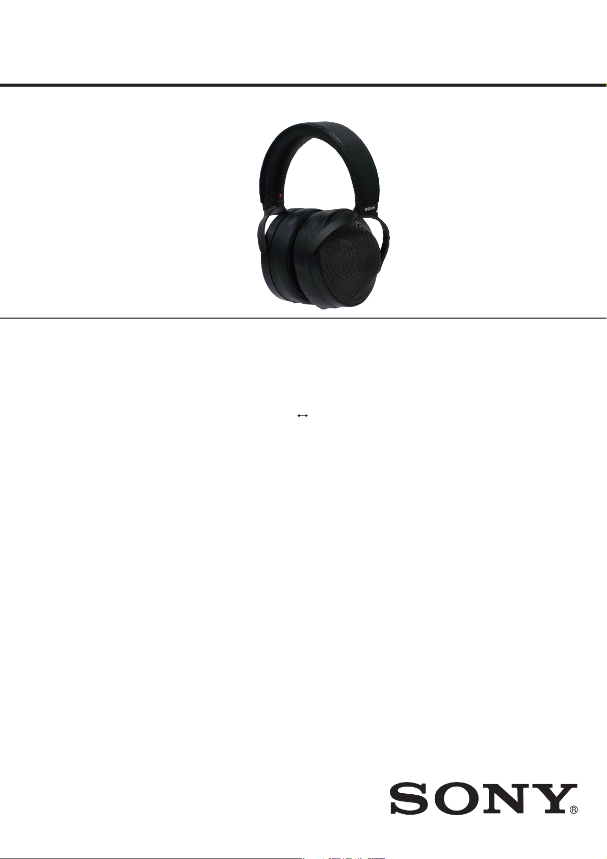
MDR-Z1R
99
SECTION 4
ACCESSORIES
4-593-590-13 MANUAL, INSTRUCTION
(ENGLISH, FRENCH, GERMAN, SPANISH,
DUTCH, ITALIAN, PORTUGUESE, POLISH,
GREEK, CZECH, HUNGARIAN, RUSSIAN,
BULGARIAN, SLOVAK, SLOVENIAN,
TRADITIONAL CHINESE, KOREAN, ROMANIAN)
(Except Chinese)
4-593-590-21 MANUAL, INSTRUCTION (SIMPLIFIED CHINESE)
(Chinese)
4-593-591-11 PRODUCT INFORMATION
(ENGLISH, FRENCH, SPANISH) (Except Chinese)
4-593-591-21 PRODUCT INFORMATION
(GERMAN, DUTCH, ITALIAN) (Except Chinese)
4-593-591-31 PRODUCT INFORMATION
(RUSSIAN, TRADITIONAL CHINESE, KOREAN)
(Except Chinese)
4-593-591-42 PRODUCT INFORMATION
(SIMPLIFIED CHINESE) (Chinese)
501 A-2144-924-A CABLE (W) ASSY (Headphone cable (Approx. 3 m,
silver-coated OFC strands,
gold-plated stereo mini plug))
502 A-2144-925-A CABLE (W, BALANCE) ASSY
(Balanced-connection headphone cable
(Approx. 1.2 m, silver-coated OFC strands,
gold-plated balanced standard plug))
503 X-2594-062-1 HARD CASE ASSY (Hard case: without serial plate)
(See Note)
504 1-566-410-41 ADAPTOR, PLUG (Gold-plated unimatch plug
adaptor (stereo phone plug ystereo mini jack)
501
Headphone cable
(Approx. 3 m, silver-coated OFC strands, gold-plated stereo mini plug) (1)
503
Hard case (1)
(Without serial plate)
504
Gold-plated unimatch plug adaptor
(stereo phone plug ystereo mini jack) (1)
502
Balanced-connection headphone cable
(Approx. 1.2 m, silver-coated OFC strands, gold-plated balanced standard plug) (1)
Note: When the hard case assy (Ref. No. 503) is replaced, refer to
“NOTE OF REPLACING THE HARD CASE ASSY” on
page 2.