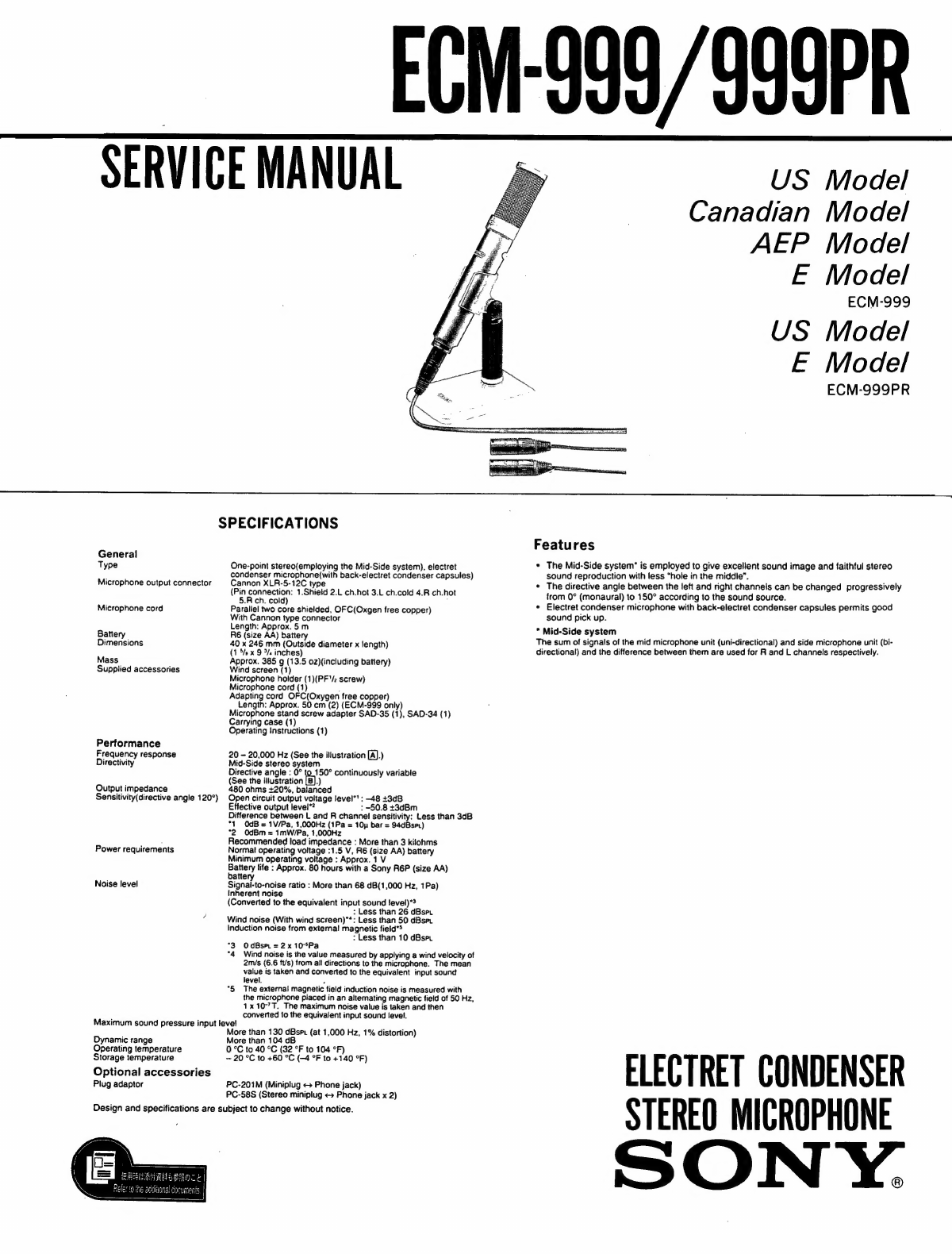
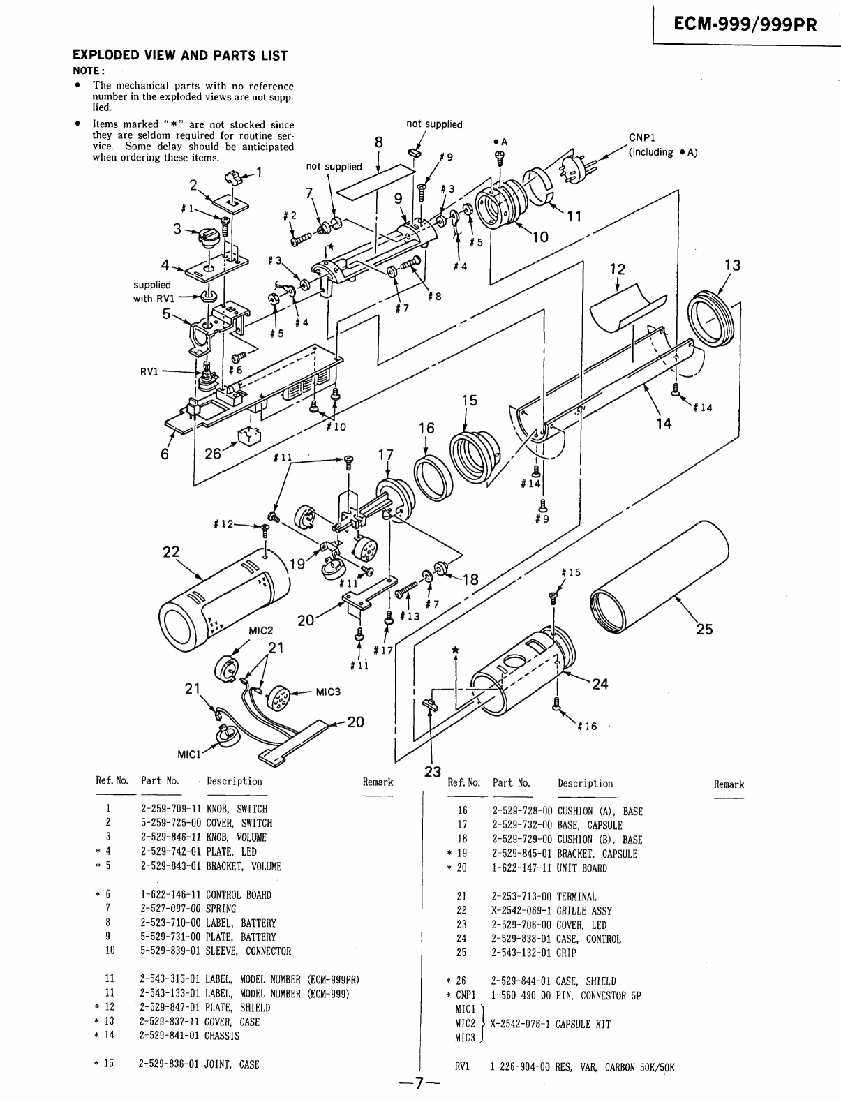
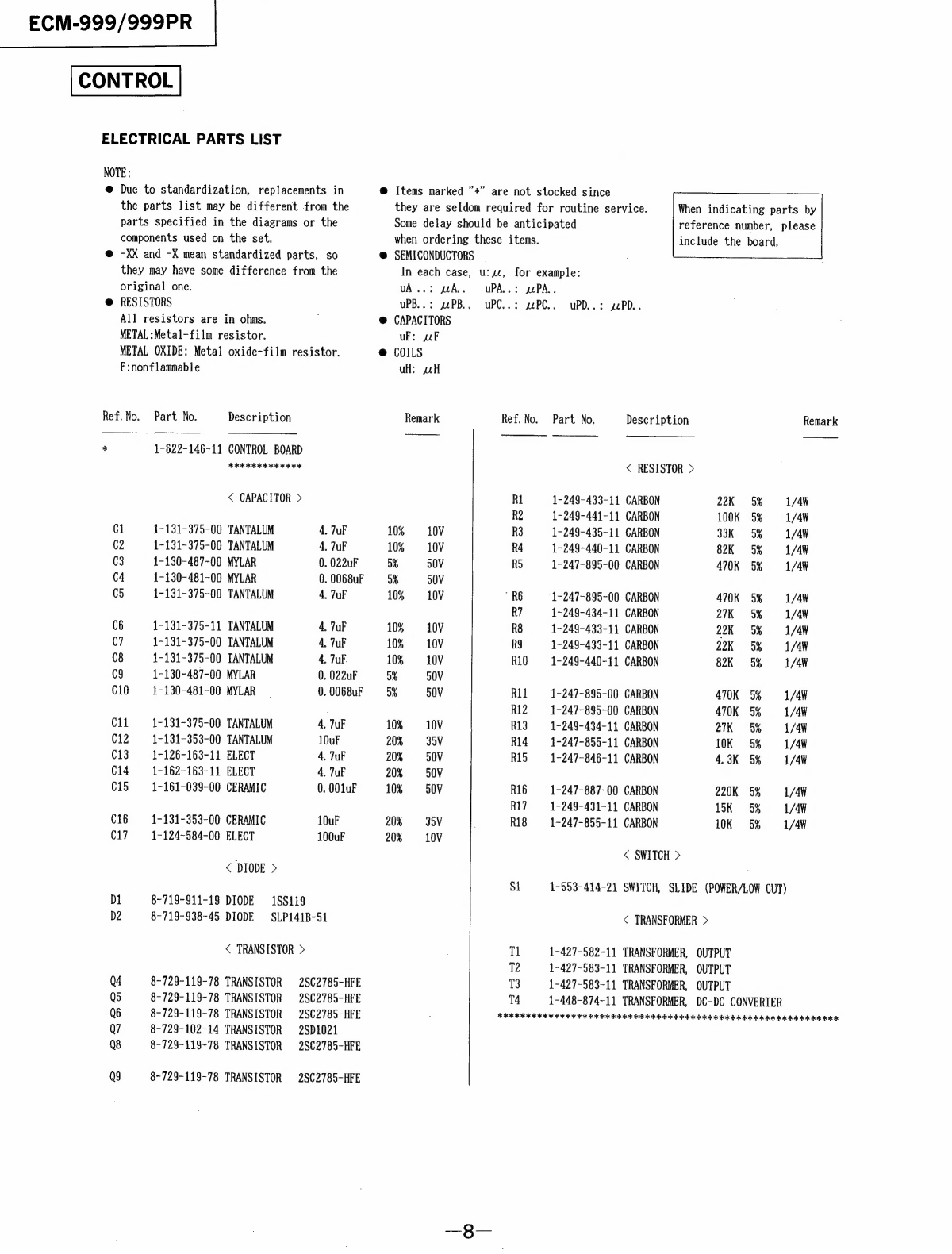
Sony ECM-999 User manual

EGM-999/999PR
SERVICE
MANUAL
SPECIFICATIONS
General
Type
Microphone
output
connector
Microphone
cord
Battery
Dimensions
Mass
Supplied
accessories
Performance
Frequency
response
Directivity
Output
impedance
Sensitivity(directive
angle
120°)
Power
requirements
Noise
level
One-point
stereo(employing
the
Mid-Side
system),
electret
condenser
microphone(with
back-electret
condenser
capsules)
Cannon
XLR-5-12C
type
(Pin
connection:
1.Shield
2.L
ch.hot
3.L
ch.cold
4.R
ch.hot
5.R
ch.
cold)
,
Parallel
two
core
shielded,
OFC(Oxgen
free
copper)
With
Cannon
type
connector
Length:
Approx.
5m
R6
(size
AA)
battery
40
x
246
mm
(Outside
diameter
x
length)
(1
5/2
x
9
5/
inches)
Approx.
385
g
(13.5
0z)(including
battery)
Wind
screen
(1)
Microphone
holder
(1)(PF'/2
screw)
Microphone
cord
(1)
.
Adapting
cord
OFC(Oxygen
free
copper)
Length:
Approx.
50
cm
(2)
(ECM-999
only)
Microphone
stand
screw
adapter
SAD-35
(1),
SAD-34
(1)
Carrying
case
(1)
Operating
instructions
(1)
20
-
20,000
Hz
(See
the
illustration
[A].)
Mid-Side
stereo
system
Directive
angle
:
0°
to
150°
continuously
variable
(See
the
illustration
'B})
480
ohms
+20%,
balanced
Open
circuit
output
voltage
level’:
-48
+3dB
Effective
output
level*?
:
-50.8
+3dBm
Difference
between
L
and
R
channel
sensitivity:
Less
than
3dB
*1
OdB
=
1V/Pa,
1,000Hz
(1Pa
=
10
bar
=
94dBsrt)
°2
0dBm
=
imW/Pa,
1,000Hz
Recommended
load
impedance
:
More
than
3
kilohms
Normal
operating
voltage
:1.5
V,
R6
(size
AA)
battery
Minimum
operating
voltage
:
Approx.
1
V
Battery
life
:
Approx.
80
hours
with
a
Sony
R6P
(size
AA)
battery
Signai-to-noise
ratio
:
More
than
68
dB(1,000
Hz,
1Pa)
Inherent
noise
(Converted
to
the
equivalent
input
sound
!evel)*?
:
Less
than
26
dBspt
Wind
noise
(With
wind
screen)"*:
Less
than
50
dBset
Induction
noise
from
external
magnetic
field"*
:
Less
than
10
dBset
°3
OdBsm
=2x
10°Pa
°4
Wind
noise
is
the
value
measured
by
applying
a
wind
velocity
of
2ms
(6.6
ft/s)
from
ail
directions
to
the
microphone.
The
mean
value
is
taken
and
converted
to
the
equivalent
input
sound
level.
.
"5
The
external
magnetic
field
induction
noise
is
measured
with
the
microphone
placed
in
an
altemating
magnetic
field
of
50
Hz,
1x
10°’T.
The
maximum
noise
value
is
taken
and
then
converted
to
the
equivalent
input
sound
level.
Maximum
sound
pressure
input
level
Dynamic
range
Operating
temperature
Storage
temperature
Optional
accessories
Plug
adaptor
More
than
130
dBspr
(at
1,000
Hz,
1%
distortion)
More
than
104
dB
0
°C
to
40
°C
(32
°F
to
104
°F)
—
20
°C
to
+60
°C
(-4
°F
to
+140
°F)
PC-201M
(Miniplug
«>
Phone
jack)
PC-58S
(Stereo
miniplug
«=
Phone
jack
x
2)
Design
and
specifications
are
subject
to
change
without
notice.
US
Model
Canadian
Model
AEP
Model
E
Model
ECM-999
US
Model
E
Model
ECM-999PR
Features
*
The
Mid-Side
system’
is
employed
to
give
excellent
sound
image
and
faithful
stereo
sound
reproduction
with
less
“hole
in
the
middle”.
¢
The
directive
angle
between
the
left
and
right
channels
can
be
changed
progressively
from
0°
(monaural)
to
150°
according
to
the
sound
source.
*
Electret
condenser
microphone
with
back-electret
condenser
capsules
permits
good
sound
pick
up.
*
Mid-Side
system
The
sum
of
signals
of
the
mid
microphone
unit
(uni-directional)
and
side
microphone
unit
(bi-
directional)
and
the
difference
between
them
are
used
for
R
and
L
channels
respectively.
ELECTRET
CONDENSER
STEREO
MICROPHONE
SON
Y.

ECM-999/999PR
Frequency
Response
See
illustration
[A].
Directive
angle
120°
.
8
-
L-channel
directional
pa
R-channel
directional
Directivity
axis
(0°)
nee
axis
(0°)
See
illistration
[B].
.
ee
>
~
R
(180°)
L
(180°)
[A]
@
Directional
axis(0°)
@
180°
from
the
directional
axis
foe
as
tH
inal
ins
Response
(dB)
.
i
A
|
HICH
HSE
EEN
LUT
500
1k
2k 5k
10k
20k
Frequency
(Hz)
Directive
angle
120°
7
R-channel
directional
axis
(0°)
Battery
Installation
When
to
replace
the
battery
When
the
power
is
turned
on,
the
battery
check
indicator
lights
momentarily.
When
the
battery
becomes
weak,
the
indicator
remains
dimly
lit
or
does
not
light
at
all.
In
this
case,
replace
the
battery
with
a
new
one.
Sony
R6P
(size
AA)
battery
gives
continuous
operation
of
the
microphone
for
about
80
hours.
Notes
on
battery
To
avoid
damage
to
the
unit
caused
by
battery
leakage
and
corrosion;
*
Install
the
battery
with
correct
polarity.
*
Do
not
try
to
recharge
batteries.
*
Remove
the
battery
if
the
microphone
is
not
to
be
used
for
a
long
period
of
time.
In
case
of
battery
leakage,
wipe
off
any
deposit
in
the
battery
compartment
before
installing
a
new
battery.

Battery
check
indicator
Directive
angle
controller
Power/Low
cut
switch
Output
terminal
Microphone
holder
Hf
the
microphone
is
connected
to
the
equipment
with
a
phone
jack
,
use
the
supplied
adapting
cord.
Connector
Red
ow.
Right
(R)
White
..........
Left(L)
.
[6]
Adapting
cord
(ECM-999
only)
AC
Sp
y
AC]
=p
Wind
screen
|
gil
eo
on
Phone
plug
=
=
=|
{ND
=
=.
—-=
age}
&omm
(o(=lay
Cbatorslile)
aloes
late
Uses
G4)
Wind
screen
_
Attach
to
reduce
wind
or
breathing
noise.
[2]
[3]
[4]
[5]
[6]
Battery
check
indicator
When
the
power/low
cut
switch
is
set
to
M
from
OFF,
the
indicator
lights
momentarily.
This
indicates
that
the
battery
is
usable.
Directive
angle
controller
Selects
the
directive
angle
between
the
left
and
right
channels
in
accordance
with
sound
source
or
sound
level.
Location
of
a
microphone
Sound
sources
|
To
record
with
a
monaural
tape
recorder
|
oe
|
mY
To
pick
up
a
narrower
sound
source
90°
e.g.
*
An
instrumental
solo
5
Close
to
the
sound
source
120°
120°
¢
Bird
and
insect
song
To
pick
up
a
wider
sound
source
i)
150°
e.g.
*
An
orchestra,
chorus
*
A
moving
train,
airplane,
motor
car
race
«
Speeches
at
a
conference
¢
Natural
sounds,
urban
sounds,etc.
Rather
farther
away
from
the
sound
source
While
picking
up
sounds
from
wider
(narrower)
sound
source,
avoid
moving
the
microphone
itself,
so as
to
maintain
the
original
sound
balance.
Microphone
holder
Install
to
the
optional
microphone
stand.
Power/Low
cut
switch
|
OFF
|
To
turn
off
the
power
To
pick
up
sounds
such
as
musical
instruments
and
natural
sounds
away
from
the
sound
orr—>
“
-—v
TIT)
| 4
ses
To
pick
up
a
human
voice
more
clearly
To
reduce
low
range
noise
such
as
wind
.
Adapting
cord
If
the
microphone
is
connected
to
the-equipment
with
a
phone
jack
,
use
the
supplied
adapting
cord.
Microphone
unit
How
to
direct
the
microphone
Note
Direct
the
microphone
to
the
sound
source
vertically.
When
the
microhone
is
used
upside
down,
L
and
R
Connection
To
attach
1
Align
the
connector
with
the
output
terminal
of
the
microphone.
CEM
To
detach
insert
the
connector
until
a
click
is
heard.
While
pressing
the
projection,
pull
out
the

DISASSEMBLY
Note:
Follow
the
disassembly
procedure
in
the
numerical
order
given.
©
precision
screwdriver
grip
control
case
@
POWER
©
switch
(direction
select)
CAPSULE
UNIT
BOARD
SECTION
grill
assy
in
the
pinhole
and
turn
to
the
stick
the
tip
of
tweezers
and
soon
counter
clock
wise

PRINTED
WIRING
BOARDS
I
Oa
or
ZO
ou
|
(BATTERY®)
LUG
a)
RV1-1
500k2B
-RV1-2
50kQC
MIC3
MIC2
Co}
(R)
(L)
VOLUME
MOUNTING
BRACKT
Y
ke)
MIC
(FRONT)
Z__L\
LUG
(BATTERYO©)
TI
T2
13
CNP
1
T4

SCHEMATIC
DIAGRAM
(UNIT
BOARD
]
{CONTROL
BOARD
]
Qi~3
Low
cur
04
2SK377
OFF
->M
ev
2S8C2785
\MPEADANCE
CONVERTER
if
meters
BUFFER
AMP
|
eR
al
ak
12
Ro
cl
c2
aes
A9.2V
Ql
A9.2V
4.7/\0V
oO)
ee
4.7/10V
AG
ogee
o1og6e
(vr
~~
D
HE
F
R
)
cs
[wc
6
LEAs
mu
>
Ove]
12/1Y
2
‘
S)
3H
4S
RI
ON
alg
3av¥t
*"@
:
22k
RB
\
R4
RG
=
82:
R7
33k
\
kK
Fa70K
S57,
®@
\
an
7
ay
1OV
)
|
Ro
-
22k
0)
TI
®
|
Q5
QNIES
|
Si-2
28C2785
|
Low
CUT
BUFFER
AMP
@
OFF
eM
Vv
|
ac
|
RII
cé
@
|
it
7
o
4)
9
clo
a1
|A9.2V
4.7/\0V
@!
+
0.022
00068
+
N
B
cll
ON
aFrov
;
aS
Feet
R8
3.8ev7]
+
22k
RIO
O
Py
82k
ee
®
!
=
Q9
Q8
Q7
Q6
Si-3
2SC2785
2502785
2801020
2S8C2785
_—
02
POWER
DC-DC
CONVERTER
DC-DC
CONVERTER
LIPPLE
FILTER
SLPI41B
OFF
MeV
T
7
1.5V
|
:
v4
DI
9.2V
L
ra
ras
rs
t_
A
J
TW
al
RIB
Be
@
©
1.5V
16
:
ae
|
L5V
da
i
Ok
)
i
|
6
Sie
Ak
1oG/i0V
E
2
4
)
ow
i
)
E
4.7/38V
iriev
IC
@®)
i
\h
®
@ANS
C13
a
0.03Vg7
47/35V
1000p
DI
1S1555
Note
on
Printed
Wiring
Board:
Note
on
Schematic
Diagram:
@
oO——:
parts
extracted
from
the
component
side.
e@
All
capacitors
are
in
~F
unless
otherwise
noted.
pF:
uuF.
e
———:
parts
extracted
from
the
conductor
side.
50WV
or
less
are
not
indicated
except
for
electrolytics.
and
°
@
:
Through
hole.
tantalums.
°
:
Pattern
on
the
side
which
is
seen.
e
All
resistors
are
in
ohms,
1/4W
unless
otherwise
noted.
°
:
Pattern
of
the
rear
side.
kQ:
10000,
MQ:
1000kqQ.
o
Voltages
are
de
with
respect
to
ground
unless
otherwise
noted.
e
Semiconductor
Lead
Layouts
2SK377-K
2SC1020H
181555
SLP141B
2S8C2785
|
:
letter
side
cathode
(Ss
4
a
anode
||
©
cathode
D
anode
S
ece

EXPLODED
VIEW
AND
PARTS
LIST
NOTE:
e
The
mechanical
parts
with
no
reference
number
in
the
exploded
views
are
not
supp-
lied.
@
Items
marked
“*”
are
not
stocked
since
they
are
seldom
required
for
routine
ser-
vice.
Some
delay
should
be
anticipated
when
ordering
these
items.
:
1
not
supplied
.
20
MIC2
21
t
0
R
Ref.No.
Part
No.
-
Description
1
2-259-709-11
KNOB,
SWITCH
2
5-259-725-00
COVER,
SWITCH
3
2-529-846-11
KNOB,
VOLUME
*
4
2-529-742-01
PLATE,
LED
*
5
2-529-843-01
BRACKET,
VOLUME
*
6
1-622-146-11
CONTROL
BOARD
7
2-527-097-00
SPRING
8
2-523-710-00
LABEL,
BATTERY
g
5-529-731-00
PLATE,
BATTERY
10
5-529-839-01
SLEEVE,
CONNECTOR
Il
2-543-315-01
LABEL,
MODEL
NUMBER
(ECM-999PR)
Mi
2-543-133-01
LABEL,
MODEL
NUMBER
(ECM-999)
*
12
-2-529-847-01
PLATE,
SHIELD
*
43
2-529-837-11
COVER,
CASE
*
14
2-529-841-01
CHASSIS
*
415
2-529-836-01
JOINT,
CASE
|
ECM-999/999PR
~
not
supplied
emark
CNP1
(including
®
A)
25
Ref.
No.
Part
No.
Description
Remark
16
2-529-728-00
CUSHION
(A),
BASE
17
2-529-732-00
BASE,
CAPSULE
18
2-529-729-00
CUSHION
(B),
BASE
*
19
2-529-845-01
BRACKET,
CAPSULE
«
20
1-622-147-11
UNIT
BOARD
21
2-253-713-00
TERMINAL
22
X-2542-069-1
GRILLE
ASSY
23
2-529-706-00
COVER,
LED
24
2-529-838-01
CASE,
CONTROL
25
2-543-132-01
GRIP
*
26
2-529-844-01
CASE,
SHIELD
*
(NPL
1~-560-490-00
PIN,
CONNESTOR
5P
MICi
MIG2
>
X-2542-076-1
CAPSULE
KIT
MIC3
RV1
1-226-904-00
RES,
VAR,
CARBON
50K/50K

ECM-999/999PR
ELECTRICAL
PARTS
LIST
NOTE:
@
Due
to
standardization,
replacements
in
@
Items
marked
”*”
are
not
stocked
since
the
parts
list
may
be
different
from
the
they
are
seldom
required
for
routine
service.
When
indicating
parts
by
parts
specified
in
the
diagrams
or
the
Some
delay
should
be
anticipated
reference
number,
please
components
used
on
the
set.
when
ordering
these
items.
include
the
board
@
-XX
and
-X
mean
standardized
parts,
so
@
SEMICONDUCTORS
they
may
have
some
difference
from
the
In
each
case,
u:z,
for
example:
original
one.
uA..:
wA.
uPA..:
uPA.
@
RESISTORS
uPB..:
sPB..
uPC..:
sPC..
uPD..:
xPD..
All
resistors
are
in
ohms.
,
@
CAPACITORS
METAL
:Metal-film
resistor.
uF:
uF
METAL
OXIDE:
Metal
oxide-film
resistor.
@
COILS
F:nonflammable
uH:
4H
Ref.No.
Part
No.
Description
Remark
Ref.
No.
Part
No.
Description
Remark
*
1-622-146-11
CONTROL
BOARD
FEO
oo
ook
<
RESISTOR
>
<
CAPACITOR
>
Rl
1-249-433-11
CARBON
22K
5%
1/4W
R2
1-249-441-11
CARBON
100K
5%
1/4W
C1
1-131-375-00
TANTALUM
4.
TuF
10%
10V
R3
1-249-435-11
CARBON
33K
5%
1/4W
C2
1-131-375-00
TANTALUM
4.
7uF
10%
10V
R4
1-249-440-11
CARBON
82K
5%
1/4W
C3
1-130-487-00
MYLAR
0.
022uF
5%
50V
R5
1-247-895-00
CARBON
470K
5%
1/4W
C4
1-130-481-00
MYLAR
0.
0068uF
o%
30V
C5
1-131-375-00
TANTALUM
4.
7uF
10%
10V
RE
‘1-247-895-00
CARBON
470K
5%
1/4W
R7
1-249-434-11
CARBON
27K
=
5%
1/4W
C6
1-131-375-11
TANTALUM
4.
7uF
10%
10V
R8
1-249-433-11
CARBON
22K
5%
1/4W
C7
1-131-375-00
TANTALUM
4,
TuF
10%
10V
R9
1-249-433-11
CARBON
22K
5%
1/4W
C8
1-131-375-00
TANTALUM
4.
TuF
10%
10V
R10
1-249-440-11
CARBON
82K
5%
1/4W
C9
1-130-487-00
MYLAR
0.
022uF
5%
50V
C10
1-130-481-00
MYLAR
0.
0068uF
5%
50V
R11
1-247-895-00
CARBON
470K
5%
1/4W
R12
1-247-895-00
CARBON
470K
5%
1/4W
C11
1-131-375-00
TANTALUM
4.
TuF
10%
10V
R13
1-249-434-11
CARBON
27K
5%
/4W
C12
1-131-353-00
TANTALUM
10uF
20%
35V
R14
1-247-855-11
CARBON
10K
5%
1/4W
C13
1-126-163-11
ELECT
4.
7uF
20%
50V
R15
1-247-846-11
CARBON
4.3K
5%
1/4¥
C14
1-162-163-11
ELECT
4.
TuF
20%
50V
C15
1-161-039-00
CERAMIC
0.
001uF
10%
~=—50V
R16
1-247-887-00
CARBON
220K
5%
1/4W
R17
1-249-431-11
CARBON
15K
5%
1/44
C16
1-131-353-00
CERAMIC
10uF
20%
35V R18
1-247-855-11
CARBON
10K
5%
1/4¥
C17
1-124-584-00
ELECT
100uF
20%
10V
<
SWITCH
>
<
DIODE
>
Si
1-553-414-21
SWITCH,
SLIDE
(POWER/LOW
CUT)
D1
8-719-911-19
DIODE
188119
D2
8-719-938-45
DIODE
SLP141B-51
<
TRANSFORMER
>
<
TRANSISTOR
>
.
Tl
1-427-582-11
TRANSFORMER,
OUTPUT
T2
1-427-583-11
TRANSFORMER,
OUTPUT
Q4
8-729-119-78
TRANSISTOR
2SC2785-HFE
T3
1-427-583-11
TRANSFORMER,
OUTPUT
Q5
8-729-119-78
TRANSISTOR
2SC2785-HFE
T4
1-448-874-11
TRANSFORMER,
DC-DC
CONVERTER
Q6
8-729-119-78
TRANSISTOR
2SC2785-HFE
.
FOCI
COO
OOOO
OO
IO
IO
IOI
OIC
OOOO
IOI
I
OOO
IO
IOI
IO
ok
Iorok
Q7
8-729-102-14
TRANSISTOR
2SD1021
Q8
8-729-119-78
TRANSISTOR
2SC2785-HFE
Q9
8-729-119-78
TRANSISTOR
2SC2785-HFE

Ref.
No.
Qi
Q2
Q3
Part
No.
Description
Remark
1-622-147-11
UNIT
BOARD
AIG
jatokok
2-523-713-00
TERMINAL
7-623-505-01
LUG,
2
<
TRANSISTOR
>
8-729-824-20
TRANSISTOR
8-729-824-20
TRANSISTOR
8~729-824-20
TRANSISTOR
2SK377-K1
28K377-K1
2SK377-K1
AICI
SII
II
IO
III
IO
IOI
SI
II
IOI
II
IR
IO
IO
IOI
OI
Ok
sok
CNP1
MIC1
MIC2
MIC3
RV1
MISCELLANEOUS
ORR
IO
kk
foe
1~560-490-00
PIN,
CONNECTOR
oP
X-2542-076-1
CAPSULE
KIT
1-226-904-00
RES,
VAR,
CARBON
50K/50K
SEIOICI
OOOO
IOI
IOI
IO
IOI
IO
IO
OO
OR OR
IO
OI
OOK
#1
#2
#3
#4
#5
#6
#7
#8
#9
#10
#11
#12
#13
#14
#15
#16
#17
ESIC
II
I
ok
kok
okok
HARDWARE
LIST
FICO
GO
IO
OO
iookokok
dog
tok
7-627-552-47
SCREW,
PRECISION
+P
1.
7X4
7-621-255-42
SCREW
+P
2X6
7-623-420-07
LW
2,
TYPE
B
7-623-505-01
LUG,
2
7-622-205-05
NUT
M2
TYPE2
7-685-102-21
SCREW
+P
2X4
TYPE2
SLIT
7-688-001-01
W
2.
MIDDLE
7-621-255-72
SCREW
+P
2X12
7-627~452-38
SCREW,
PRECICION
+K
2X5
7-621-255-15
SCREW
+P
2X3
7-627-551-67
SCREW,
PRECISION
+P
1.
4X3.
5
7-627-452-28
SCREW,
PRECISION
+RK
2X4
7-621-256-05
SCREW
+P
2X16
7-627-452-17
SCREW,
PRECISION
+K
2X3
7-627-452-18
SCREW,
PRECICION
+K
2X3
7-627-452-58
SCREW
+K
2X6
TYPE1
7-685-102-21
SCREW
+P
2X4
TYPE2
SLIT
AICCCR
IOI
IO
IOI
IOI
IOI
OIC
OIO
II
OIO
ICO
OO
I
ICO
IOI
FOR
TOR
BOK
Ref.
No.
ECM-999/999PR
Part
No.
Description
Remark
ACCESSORIES
&
PACKING
MATERIALS
CII
OI
OIG
OI
nO
OIOfok
1-696-451-11
CABLE,
MICROPHINE
(2
CORE)
1-696-566-11
CORD,
MICROPHONE
(DIA.5)
(2
CORE)
(ECM-
999)
2-100-951-04
ADAPTER,
SCREW,
STAND
(SAD-34)
2-100-952-00
ADAPTER,
SCREW,
STAND
(SAD-35)
2-543-210-01
INDIVIDUAL
CARTON
(ECM-999)
2-543-335-01
INDIVIDUAL
CARTON
(ECM-999PR)
3-795-503-11
MANUAL,
INSTRUCTION
(ENGLISH,
FRENCH.
SPANISH,
GERMAN,
DUTCH,
SWEDISH,
ITALIAN,
PORTUGUESE)
A-4580-007-A
SCREEN
ASSY,
WINDOW
X-2529-802-1
HOLDER
ASSY,
MICROPHONE

ECM-999/999PR
|
Sony
Corporation
English
Consumer
A
&V
Products
Company
Pri
ed
in
Japan
9-957-493-12
Personal
A
&
V
Products
Div.
©
1994.
10
Published
by
Home
A
&
V
Products
Div.
—_
1
O—
Quality
Engineering
Dept.

__
ECM-999/999PR
SERVICE
MANUAL
Canadian
Mode!
AEP
Model
E
Model
.
ECM-999
SUPPLEMENT-1
sss
@2.-
Moe
.
E
Model
File
this
supplement
with
the
service
manual.
ECM-999PR
Subject:
CORRECTION
.
CHANGE
THE
PC
BOARD
(ENG-95026)
1.
CORRECTION
ay”
:
indicates
corrected
portion.
INCORRECT
CORRECT
Part
No.
Description
Part
No.
Description
Remark
2-529-742-01
PLATE,
LED
*
2-529-842-01
PLATE,
LED
5-§29-731-00
PLATE,
BATTERY
2-529-731-00
PLATE,
BATTERY
5-529-839-01
SLEEVE,
CONNECTOR
2-529-839-01
SLEEVE,
CONNECTOR
2.
EXPLODED
VIEW
Former
Type
New
Type
.
Ref.
No.
Part
No.
Description
Part
No.
Description
*
6
1-622-146-11
CONTROL
BOARD
*
1-658-256-11
CONTROL
BOARD
*
26
2-529-844-01
CASE,
SHIELD
——_———-

ECM-999/999PR
3.
SCHEMATIC
DIAGRAM
[CONTROL
BOARD]
— -
|
MIC3
cui7-04
(>)
(RIGHT)
Q3
29K3577-B
IMPE®ANCE
CONVERTER
RVI
BIRECTIVE
|
ANGLE
CONTROLLER
Ld
VV
——-
{LOW
CUT)
C-ac
=
g—
|
cotvetter
1.5
BF
a6
a!
2504116
RBA
ID
]
>
ues
BATTERY
27
(
eee
)
>
INDICATOR
10.4
cig
25307-B
atzio
(Pr
°
6ihy
RIT
ches
A
IMPEDANCE
ec)
9
es
(FRONT)
CONVERTER
C12
C13
+1014
0.5)
4
10
1a
TW
cis
CO)
a7
(¥)
—
a
:
:
a
2581068
oN
I
G6
a7-9
subi
a1B
pee
ud
a
poche
IEC
BESIGNATION
UN
WV
VV
FILTER
CONVERTER
bei
(
ae
)
|T
OFF]
——
1PCS,
1.5V
(LOW
CUT)
[GFF}—~[¥]—>[¥)
BOARD
S1-1
(POWER)
04
aa
=
=
i
St
Note:
e
All
capacitors
are
in
uF
unless
otherwise
noted.
pF:
uuF
50WV
or
less
are
not
indicated
except
for
electrolytics
and
tantalums.
®@
Allresistors
are
in
Q
and
1/4
W
or
less
unless
otherwise
"specified.
®
:
B+
Line
@
Power
voitage
is
dc
1.5V
and
fed
with
regulated
dc
power
supply
from
battery
terminal.
Voltage
is
dc
with
respect
to
ground
under
no-signal
conditions.
®
no
mark:
POWER:
M
*
:
Impossible
measurement
point
@
Voltages
are
taken
with
a
VOM
(Input
Impedance
10MQ).
Voltage
variations
may
be
noted
due
to
normal
production
tolerances.

4.
PRINTED
WIRING
BOARDS
RVI
DIRECTIVE
ANGLE
{CONTROL
/
Ovex
BRN
’
VOLUME
MOUNTING
DRY
BATTERY
\"
BRACKET,
SIZE
"AA
(IEC
DESIGNATION
R6)
IPC
CON
GLE
eg)
SS
PC
RR
ORIEL
ESE
LDR
LNA
D
ELL
IEEE
LALIT
IE
TIES
S,
1.5V
:
parts
extracted
from
the
conductor
side.
:
Through
hole.
Pattern
on
the
side
which
is
seen.
(The
other
!ayer’s
patterns
are
not
indicated.)
MIC
|
BLU
(FRONT)
MIC
2
(i
(LEFT)
>
WHT
ECM-999/999PR
MIC
3
(RIGHT)
@
Semiconductor
Location
Location

CONTROL
5.
ELECTRICAL
PARTS
LIST
NOTE:
@
Due
to
standardization,
replacements
in
the
parts
list
may
be
different
from
the
parts
specified
in
the
diagrams
or
the
components
used
on
the
set
@
-XX
and
-X
mean
standardized
parts,
so
they
may
have
some
difference
from
the
original
one.
@
RESISTORS
All
resistors
are
in
ohms.
METAL
:Metal-film
resistor.
METAL
OXIDE:
Metal
oxide-film
resistor.
F
:nonflammable
Ref.
No.
Part
No.
Description
*
1-658-256-11
CONTROL
BOARD
ORO
ok
ok
ok
ok ke
kok
kk
<
CAPACITOR
>
C1
1-107-686-11
TANTAL.
CHIP
C2
1-107-686-11
TANTAL.
CHIP
C3
1-104-555-11
FILM
CHIP
C4
1-104-549-11
FILM
CHIP
C5
1-104-851-11
TANTAL.
CHIP
C6-8
1-107-686-11
TANTAL.
CHIP
cg
1-104-555-11
FILM CHIP
C10
1-104-549-11
FILM
CHIP
C11
1-104-851-11
TANTAL.
CHIP
C12
1-104-851-11
TANTAL.
CHIP
C13
1-124-779-00
ELECT
CHIP
C14
1-124-775-00
ELECT
CHIP
C15
1-164-346-11
CERAMIC
CHIP
C16
1-164-232-11
CERAMIC
CHIP
C17
1-124-779-00
ELECT
CHIP
C18
1-126-205-11
ELECT
CHIP
<
DIODE
>
D1
8-719-975-40
DIODE
RB4ii
D2
8-719-977-28
DIODE DTZ10
D3
8-719-938-45
LED
SLP141B
<
TRANSISTOR
Q4
8-729-013-33
TRANSISTOR
Q5
8-729-013-33
TRANSISTOR
Q6
8-729-231-74
TRANSISTOR
Q7
8-729-800-37
TRANSISTOR
Q8
8-729-800-37
TRANSISTOR
Q9
8-725-800-73
TRANSISTOR
<
RESISTOR
>
R1
1-216-081-00
METAL
CHIP
R2
1-216-097-00
METAL
CHIP
4.
TuF
4.
TuF
0.
022uF
0.
0068uF
10uF
4.
TuF
0.
022uF
0.
0068uF
10uF
10uF
10uF
10uF
luF
0.
OluF
10uF
47uF
D
B
91
Items
marked
”*”
are
not
stocked
since
they
are
seldom
required
for
routine
service.
Some
delay
should
be
anticipated
when
ordering
these
items.
When
indicating
parts
by
reference
number,
please
include
the
board.
In
each
case,
u:
x,
for
example:
SEMICONDUCTORS
uA..:
WA.
uPB..:
sePB..
CAPACITORS
uF:
uF
COILS
uH:
«aH
Remark
20% 16V
20%
16V
5%
16V
5%
16V
20%
10V
20%
16V
5%
16V
5%
16V
20%
10V
20% 10V
20%
16V
20%
16V
16V
50V
20%
16V
20%
6.
3V
(BATTERY
CHECK
INDICATOR)
>
uPA.
.
:
PA.
.
:
yePC..
uPD..:
gPD..
Ref.
No.
Part
No.
Description
Remark
R3
1-216-085-00
METAL
CHIP
33K
5%
1/10¥
R4
1-216-095-00
METAL
CHIP
82K
5%
1/10¥
R5
1-216-113-00
METAL
CHIP
470K
5%
1/10W
R6
1-216-113-00
METAL
CHIP
470K
5%
1/10W
R7
1-216-083-00
METAL
CHIP
27K
=
5%
1/10W
R8
1-216-081-00
METAL
CHIP
22K
=
o%
1/10W
R9
1-216-081-00
METAL
CHIP
22K
=
5%
1/10W
R10
1-216-095-00
METAL
CHIP
82K
5%
1/10W
R11
1-216-113-00
METAL
CHIP
470K
5%
1/10W
R12
1-216-113-00
METAL
CHIP
470K
5%
1/10¥
R13
1-216-083-00
METAL
CHIP
27K
=
5%
1/10W
R14
1-216-073-00
METAL
CHIP
10K
5%
1/10W
R15
1-216-043-00
METAL
CHIP
560
5%
1/10¥
R16
1-216-021-00
METAL
CHIP
68
5%
1/10¥
R17
1-216-073-00
METAL
CHIP
10K
=
5%
1/10¥
<
TRANSFORMER
>
Tl
1-427-582-11
TRANSFORMER,
OUTPUT
T2
1-427-583-11
TRANSFORMER,
OUTPUT
T3
1-427-583-11
TRANSFORMER,
OUTPUT
T4
1-429-239-11
TRANSFORMER,
DC-DC
CONVERTER
<
SWITCH
>
Si
1-553-414-21
SWITCH,
SLIDE
(POWER/LOW
CUT)
2
III
III
III
IOI
III
IO
IO
bk
1-622-147-11
UNIT
BOARD
ORR
ROR
RE
2-923-713-00
TERMINAL
7-623-505-01
LUG,
2
2804117-GRBL-TE85L
2804117-GRBL-TE85L
2804116-GL
2SD1048-X7
2SD1048-X7
2SB815B7-TA
22K
oO%
100K
5%
1/10¥
1/10
<
TRANSISTOR
>
Ql
8-729-031-76
TRANSISTOR
2SK377-B
Q2
8-728-031-76
TRANSISTOR
2SK377-B
Q3
8-729-031-76
TRANSISTOR
2SK377-B
AO
OR
Ro
RR
I
OR
IO
IOI
OIC
lig
lO
ii
foto
ioiok
digi
iofoioiogok

ECM-999/999PR
Ref.
No.
Part
No.
Description
Remark
MISCELLANEOUS
2
tio
ok
dojok
tok
*
CNP1
1-560-490-00
PIN,
CONNECTOR
SP
MIC1-3
X-2542-076-1
CAPSULE
KIT
RV1
1-226-904-00
RES,
VAR,
CARBON
50K/50K
9-957-493-8381
(DIRECTIVE
ANGLE
CONTROLLER)
Sony
Corporation
Consumer
A
&
V
Products
Company
Personal
A
&
V
Products
Div.
—§—
English
95J0476-1
Printed
in
Japan
©
1995.
10
Published
by
Home
A
&
V
Products
Div.
Quality
Engineering
Dept.
Other manuals for ECM-999
1
This manual suits for next models
1
Table of contents
Other Sony Microphone manuals
Popular Microphone manuals by other brands

HME
HME DM5 Quick Reference Installation Guide

König
König SAS-MIC10 manual

Merlaud
Merlaud DRS 849 L-M Operation & maintenance instructions

Electro-Voice
Electro-Voice RE20 Technical specifications

Sennheiser
Sennheiser evolution wireless g3 SKM 300 instruction manual

Inter-m
Inter-m NRM-8000A Operation manual