WRT-810A
3369
Notice
for
customers
in
the
U.S.A.
Use
of
Sony
wireless
devices
is
regulated
by
the
Federal
Communica-
tions
Commission
as
described
in
Part
74
subpart
H
of
the
FCC
regulations
and
users
authorized
thereby
are
required
to
obtain
an
appropriate
license.
You
are
cautioned
that
any
changes
or
modifications
not
expressly
approved
in
this
manual
could
void
your
authority
to
operate
this
equipment.
TABLE
OF
CONTENTS
1.
OPERATION
1-1.
Specifications
Cee
c
cree
ce
nnc
nn ee
ent
ecencccnenecsusvovccsccucccecncce
dul
12.
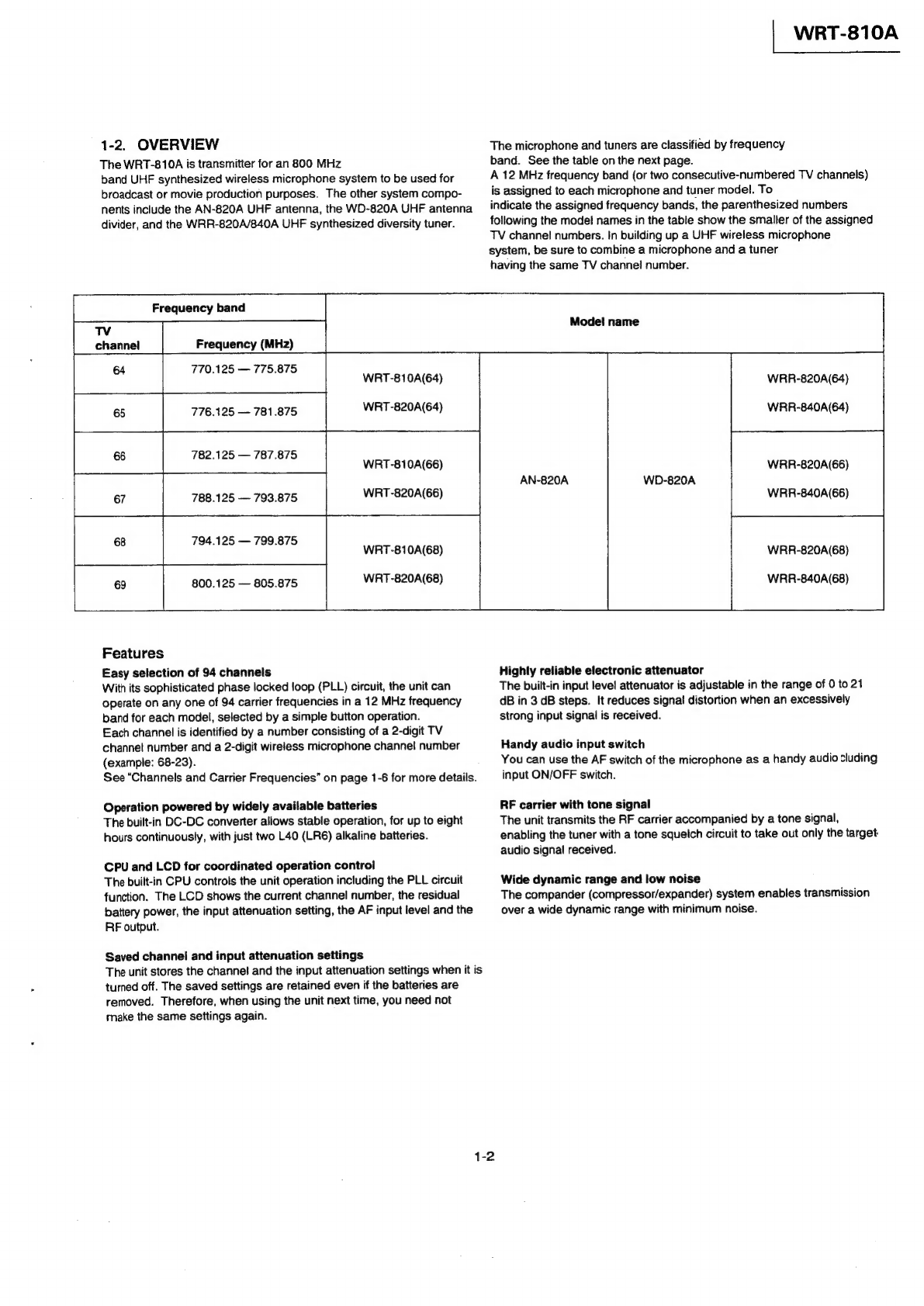
Overview
cccceterscscessreccsscccccecassessssscesssscoseerscasceces
1-2
1-3.
Parts
Identification
Comoe
nee
e
race
ence
seseesevessncucessccecce
13
14.
Inserting
Batteries
--:-::s:esssssecssssesscessveneseceseoerecees
1-3
1-5.
Changing
the
Channel
Selection
cesr:ssssceceeceseseees
14
146.
Changing
the
Input
Attenuation
Setting
«+--+
1-5
1-7.
Using
the
Transmitter
--reesscsccssesccccscccsscsccescnsceees
16
1-8.
Channels
and
Carrier
Frequencies
--+rrssscccseereeeees
16
2.
SERVICE
INFROMATION
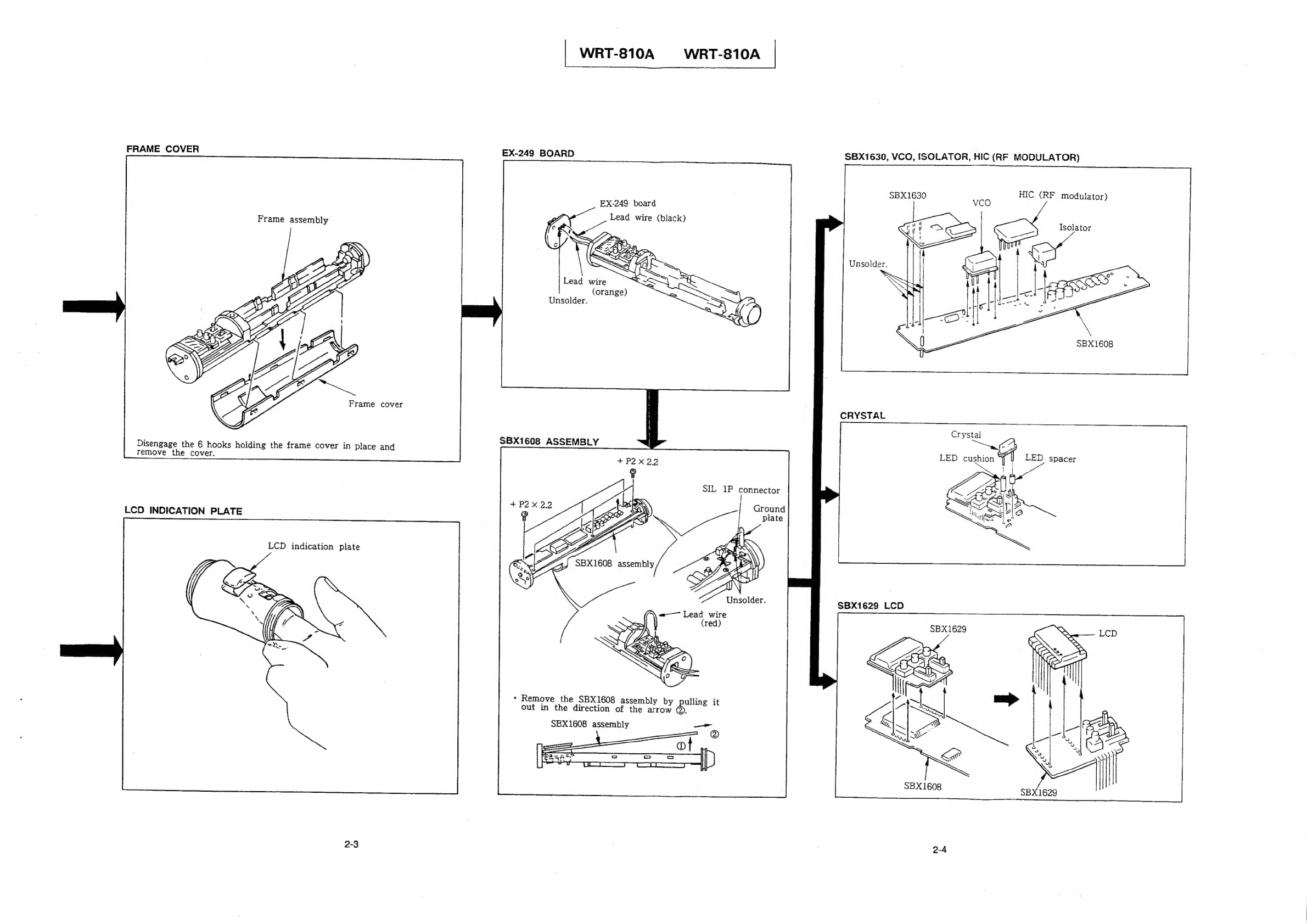
Q-1.
Disassembly
--sscccccesssssceceeesssscessscsssessessscesnseesseeees
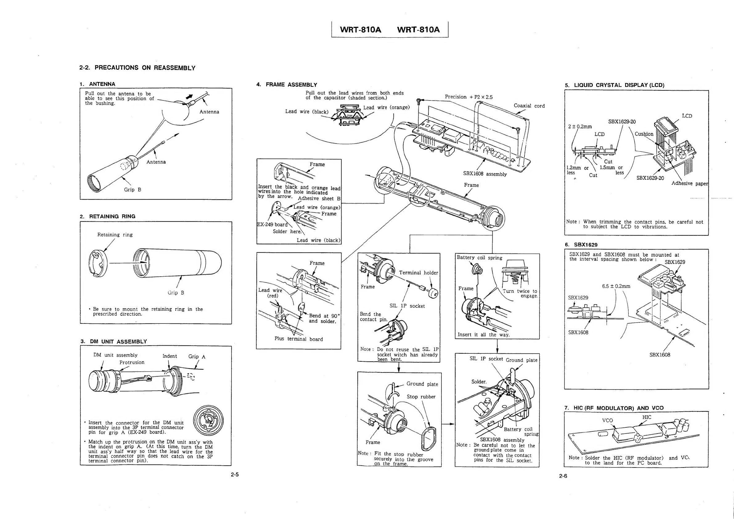
22.
Precautions
on
Reassembly
23.
Note
on
Parts
Replacement
Oe
necccccsvocveecccccccascceces
2-7
2-31.
SBX1608,
E7PROM
(1C203,
CP302)
RePlaceMent
cerrerecseeessceeeccnseececeesssessecesseuseeeoees
2-7
2-4.
Precautions
on
Chip
Parts
Replacement
---++-++--:
27
3.
ELECTRICAL
ADJUSTMENTS
3-1.
Equipment
and
Tools
3-2.
Adjustment
<rrerecercersesseteeeceeeecenssesaceesecseeeevsceneeeees
3-2-1.
+5
V
(Vcc)
Regulated
Voltage
Adjustment
--
34
3-2-2.
Carrier
Frequency
Adjustment
-s-+++:++e++ssseeree
34
3-23,
Reference
Flequency
Deviation
Adjustment
---
3-5
3-24.
Maximum
Frequency
Deviation
Adjustment
---
3-5
3-25,
Distortion
Ratio
Check
B-26,
SAN
Check
«scerssccscscacccescsconsssssccsseccscscns
3-2-7,
Frequency
Characteristics
Check
-++++++++++s1++
3-7
3-28.
RF
Power
Output
Check
<s:esscesescsseessesceeseeees
3-7
3-2-9.
Tone
Signal
Check
-s++::cesssssssssesssscssscecssseesseee
38
3-2-10.
Spurious
Emissions
Check
-s-+sesssssssssssseeseseeees
38
3-2-11.
Occupied
Band
Width
Check
crsrsssssssesseeeeee
39
4.
SEMICONDUCTOR
PIN
ASSIGNMENTS
--.---------
41
5.
BLOCK
DIAGRAM,
BOARD
LAYOUT,
SCHEMATIC
DIAGRAM
AND
LEVEL
DIAGRAM
51.
Block
Diagram
5-2.
Board
Layout
5-3.
Schematic
Diagram
6.
SPARE
PARTS
SECTION
1
OPERATION
1-1.
SPECIFICATIONS
Transmitter
and
Modulator
Section
Oscillator
Crystal
controlled
PLL
synthesizer
Carrier
frequencies
94
settings
at
125-kHz
intervals
WRT-810A
(64):
770.125
to
781.875
MHz
WRT-810A
(66):
782.125
to
793.875
MHz
WRT-810A
(68):
794.125
to
805.875
MHz
i
Tone
signal
32.768
kHz
Type
of
emission
110KF3E
RF
power
output
10
mW/2.5
mW,
selectable
(50
ohms)
Frequency
stability
Within
+0.005%
°
Less
than
2.5
pW
1/4
wavelength
wire
Spurious
radiation
Type
of
antenna
Pre-emphasis
50
us
Reference
deviation
+5
kHz
Maximum
deviation
+40 kHz
Maximum
modulation
frequency
15
kHz
100
Hz
to
13
kHz
More
than
60
dB
(A-weighted,
with
reference
deviation
at
WRR-820A/840A)
Less
than
1.5%
(with
reference
deviation)
0
to
21
dB,
variable
in
3-dB
steps
(21
dB
attenuation)
Frequency
response
Signai-to-noise
ratio
Audio
distortion
Audio
attenuator
Maximum
input
sound
pressure
level
151
dB
SPL
Microphone
unit
Uni-directional
dynamic
type
Power
Section
Power
requirements
3
V
DC
(two
L40
(LR6)
alkaline
batteries)
Battery
life
About
8
hours
at
25°C
or
77°F
(with
Sony
AM3
(LR6)
alkaline
batteries
)
Current
consumption
Less
than
170
mA
(at
3
V)
General
Operating
temperature
0°C
to
50°C
(32°F
to
122
°F)
Storage
temperature
—
30°C
to
+60°C
(—
22°F
to
+140°F)
Dimensions
48
X
238
mm
(maximum
dia./length)
(1/6
X
9%
inches)
Weight
About
300
g
(including
batteries)
(10.5
02)
Accessories
supplied
Microphone
holder
(1)
Stand
adaptor
PF
'/,
to
NS
‘/.
(1)
6-1.
Exploded
View
and
Parts
List
-+---+-+ssssssecessssees
6-1
6-2.
Electrical
Parts
List
-+ss+s++sssssscssecccscessesessensscscnces
6-3
6-3.
Accessories
Supplied
tree
eee
ens
rccencesecrecersesscncnsesenees
65
1-1
rato
ait
Sa
Ad
Soke: