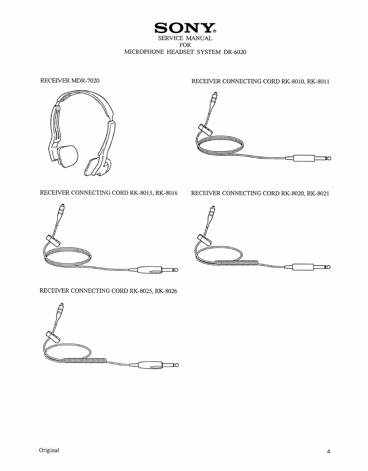
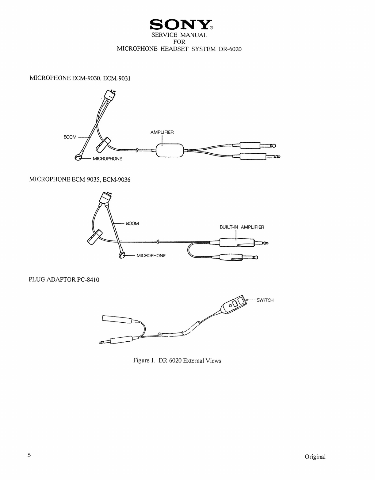
Sony DR-6020 User manual

SONTY.
SERVICE
MANUAL
for
MICROPHONE
HEADSET
SYSTEM
DR-6020
May
1994
SONY
CORPORATION,
7-35
Kitasinagawa
6-Chome,
Sinagawa-ku,
TOKYO,
141
Japan

CHAPTER/
SECTION
List
of
Effective
Pages
Record
of
Revisions
Table
of
Contents
List
of
Illustrations
List
of
Tables
Description
and
Operation
Service
Method
Disassembly
Assembly
Testing
Illustrated
Parts
List
MICROPHONE
HEADSET
SYSTEM
DR-6020
PAGE
ill
iv
1
thru
10
11
thru
12
13
thru
14
15
18
thru
19
20
thru
22
SONY.
SERVICE
MANUAL
DATE
Original
Original
Original
Original
Original
Original
Original
Original
Original
Original
Original
FOR
LIST
OF
EFFECTIVE
PAGES
CHAPTER/
SECTION
PAGE
DATE
Original

Original
SON
Y.
SERVICE
MANUAL
FOR
MICROPHONE
HEADSET
SYSTEM
DR-6020
RECORD
OF
REVISIONS
REVISION
PAGE
ISSUE
NUMBER
EFFECTED
DATE
ill

SONY.
SERVICE
MANUAL
FOR
MICROPHONE
HEADSET
SYSTEM
DR-6020
TABLE
OF
CONTENS
SECTION
nARWN
iv
SUBJECT
Title
Page
List
of
Effective
Pages
Record
of
Revisions
Table
of
Contents
List
of
Illustrations
List
of
Tables
Description
and
Operation
General
System
Configuration
Functions
and
Features
Service
Method
Disassembly
Assembly
Testing
Microphone
Main-Frame
Ass’y
Checkout
Amp
Board
Mount
Checkout
Operation
Check
on
Increasing
or
Descreasing
Power
Supply
Voltage
Illustrated
Parts
List
PAGE
Original

SON
Y:.
SERVICE
MANUAL
FOR
MICROPHONE
HEADSET
SYSTEM
DR-6020
LIST
OF
ILLUSTRATIONS
FIGURE
PAGE
I
DR-6020
External
Views
4
thru
5
2
System
Connection
Charts
6
thru
7
3
Microphone
Frequency
Response
Chart
10
4
Microphone
ECM-9030,
ECM-9031
Exploded
View
13
S
Cords
of
Plug
(A)
Ass’y
and
Plug
(B)
Ass’y
Arrangement
13
6
Cord
of
Microphone
Main-Frame
Ass’y
Arrangement
13
7
Microphone
ECM-9035,
ECM-9036
Exploded
View
14
8
Cord
Arrangement
14
9
Soldering
Position
14
10
Microphone
ECM-9030,
ECM-9031
Wiring
Diagram
16
il
Microphone
ECM-9030,
ECM-9031
Circuit
Diagram
16
12
Microphone
ECM-9035,
ECM-9036
Wiring
Diagram
17
13
Microphone
ECM-9035,
ECM-9036
Circuit
Diagram
a.
14
Wiring
for
Microphone
Main-Frame
Ass’
y
18
15
Wiring
for
Amp
Board
Mount
19
16
Microphone
ECM-9030,
ECM-9031
Exploded
View
21
17
Microphone
ECM-9035,
ECM-9036
Exploded
View
22
LIST
OF
TABLES
TABLE
PAGE
1
DR-6020
Combination
Examples
3
2
Specifications
8
thru
9
Original

1.
SONY.
SERVICE
MANUAL
FOR
MICROPHONE
HEADSET
SYSTEM
DR-6020
Description
and
Operation
A.
General
(1)
Scope
This
service
manual
with
illustrated
parts
list
(IPL)
covers
the
Sony
corporation,
DR-6020
microphone
headset
system.
B.
System
Configuration
This
equipment
is
a
microphone
headset
system
to
be
used
in
the
cockpit
and
cabin
of
a
general
aircraft.
Connected
to
the
audio
communication
system
in
the
cockpit,
it
converts
audio
signals
into
electrical
signals,
or
vice
versa,
permitting
intercommunication
inside
the
cockpit,
between
the
cockpit
and
the
cabin,
and
between
the
cockpit
and
a
ground
station.
The
system
consists
of
a
receiver
MDR-7020,
a
microphone
ECM-9035, ECM-9036,
ECM-9030, ECM-9031,
a
receiver
connecting
cord
RK-8010,
RK-8011,
RK-8020,
RK-8021, RK-8015,
RK-8016,
RK-8025,
RK-8026,
and
a
plug-adaptor
PC-8410.
These
components
can
be
used
in
combination
according
to
the
purpose.
(See
Table
1.)
C.
Function
and
Features
(See
Figure
1.)
(1)
(2)
(3)
MDR-7020
A
dynamic
type
receiver
with
earpieces
for
both
ears,
equipped
with
connector
jacks
on
both
sides
for
convenient
connection.
Unlike
with
one
ear
receiver,
using
both
ears
means
sound
pressure
levels
are
kept
low,
reducing
ear
fatigue
to
a
minimum,
and
the
open-ear
design
means
that
effects
on
the
ears
from
changes
in
air
pressure
are
also
minimized.
The
impedance
of
the
receiver
is
320
ohms.
ECM-9030,
ECM-9035
An
electret
condenser
microphone
(with
built-in
amplifier)
which
converts
the
MDR-7020
to
a
full
microphone
headset
system.
It
employs
a
high-performance
unidirectional
electret
condencer
micro-
phone
unit
at
the
end and
a
flexible
pipe
at
the
boom
to
permit
the
unit
to
be
set
in
the
most
convenient
position.
Moreover,
thanks
to
a
180-degree
rotatable
function
at
the
boom
end,
the
microphone
can
be
mounted
on
either
the
left
or
right
side
of
the
MDR-7020
for
optimum
voice
pickup.
The
microphone
operates
on
8
to
32
V
DC
(nominal
12
V
DC).
The
nominal
impedance
is
150
ohms
(AC
load)
and
the
matching
impedance
is
100
to
470
ohms.
ECM-9031,
ECM-9036
An
electret
condenser
microphone
(with
built-in
amplifier)
which
converts
the
MDR-7020
to
a
full
microphone
headset
system.
It
employs
a
high-performance
unidirectional
electret
condencer
micro-
phone
unit
at
the
end
and
a
flexible
pipe
at
the
boom
to
permit
the
unit
to
be
set
in
the
most
convenient
position.
Moreover,
thanks
to
a
180-degree
rotatable
function
at
the
boom
end,
the
microphone
can
be
mounted
on
either
the
left
or
right
side
of
the
MDR-7020
for
optimum
voice
pickup.
The
microphone
operates
on
8
to
32
V
DC
(nominal
12
V
DC).
The
nominal
impedance
is
150
ohms
(AC
load)
and
the
matching
impedance
is
100
to
470
ohms.
It
has
a
resistor
in
the
plug
for
connecting
the
receiver,
and
its
receiver
impedance
is
600
ohms.
Original

Original
(4)
(5)
(6)
(7)
(8)
SON
Y:
SERVICE
MANUAL
FOR
MICROPHONE
HEADSET
SYSTEM
DR-6020
RK-8010,
8015
A
connecting
cord
for
independent
use
of
the
receiver
MDR-7020.
It
can
be
connected
to
either
the
left
or
right
side
of
the
MDR-7020
with
the
respective
connector.
RK-8020,
8025
A
connecting
cord
for
independent
use
of
the
receiver
MDR-7020.
It
can
be
connected
to
either
the
left
or
right
side
of
the
MDR-7020
with
the
respective
connector.
It
has
curled
portion.
RK-8011,
8016
A
connecting
cord
for
independent
use
of
the
receiver
MDR-7020.
It
can
be
connected
to
either
the
left
or
right
side
of
the
MDR-7020
with
the
respective
connector.
It
has
a
resistor
in
the
plug,
and
its
receiver
impedance
is
600
ohms.
RK-8021,
8026
A
connecting
cord
for
independent
use
of
the
receiver
MDR-7020.
It
can
be
connected
to
either
the
left
or
right
side
of
the
MDR-7020
with
the
respective
connector.
It
has
curled
portion
and
has
a
resistor
in
the
plug.
Its
receiver
impedance
is
600
ohms.
PC-8410
A
plug
adaptor
with
a
push-to-talk
switch
which
enables
hand-operated
control
of
transmission.
It
is
connected
between
the
microphone
input
jack
of
the
aircraft
intercom
system
and
the
microphone
output
plug
of
the
ECM-9030, ECM-9031,
ECM-9032, ECM-9035,
ECM-9036.
The
transmitter
will
be
active
only
while
the
switch
button
is
pushed.

SONY:
SERVICE
MANUAL
FOR
MICROPHONE
HEADSET
SYSTEM
DR-6020
TABLE
1
DR-6020
Combination
Example
PURPOSE
OF
USE
Independent
use
of
the
receiver
(e.
g.
when
using
hand
microphone)
In
case
of
the
receiver
impedance
is
320
ohms.
COMBINATION
EXAMPLE
COMPONENTS
USED
MDR-7020,
RK-8010
MDR-7020,
RK-8020
MDR-7020,
RK-8015
MDR-7020,
RK-8025
MDR-7020,
ECM-9030
or
MDR-7020,
ECM-9035
Intercommunication
(e.
g.
when
using
push-to-talk
switch
on
control
yoke
or
audio
panel)
MDR-7020,
ECM-9030,
PC-8410
Intercommunication
(For
hand-operated
control
of
transmission)
|
PURPOSE
OF
USE
Independent
use
of
the
receiver
(e.
g.
when
using
hand
microphone)
or
MDR-7020,
ECM-9035,
PC-8410
In
case
of
the
receiver
impedance
is
600
ohms.
COMBINATION
EXAMPLE
COMPONENTS
USED
MDR-7020,
RK-801
1
or
MDR-7020,
RK-8021
or
MDR-7020,
RK-8016
or
MDR-7020,
RK-8026
MDR-7020,
ECM-9031
or
MDR-7020,
ECM-9036
Intercommunication
(e.
g.
when
using
push-to-talk
switch
on
control
yoke
or
audio
panel)
MDR-7020,
ECM-9031,
PC-8410
Intercommunication
(For
hand-operated
control
of
transmission)
or
MDR-7020,
ECM-9036,
PC-8410
3
Original

SONY:
SERVICE
MANUAL
FOR
MICROPHONE
HEADSET
SYSTEM
DR-6020
RECEIVER
MDR-7020
RECEIVER
CONNECTING
CORD
RK-8010,
RK-8011
U
RECEIVER
CONNECTING
CORD
RK-8015,
RK-8016
RECEIVER
CONNECTING
CORD
RK-8020,
RK-8021
—
RECEIVER
CONNECTING
CORD
RK-8025,
RK-8026
Original
4

SONY.
SERVICE
MANUAL
FOR
MICROPHONE
HEADSET
SYSTEM
DR-6020
MICROPHONE
ECM-9030,
ECM-9031
AMPLIFIER
BOOM
MICROPHONE
MICROPHONE
ECM-9035,
ECM-9036
BUILT-IN
AMPLIFIER
BOOM
MICROPHONE
PLUG
ADAPTOR
PC-8410
SWITCH
Figure
1.
DR-6020
External
Views
5
Original

SONY.
SERVICE
MANUAL
FOR
MICROPHONE
HEADSET
SYSTEM
DR-6020
1.
MDR-7020
and
RK-8010,
RK-8015,
RK-8020,
RK-8025
L-CH
D
q
R-CH
RECEIVER
RECEIVER
Yo
oer
EE
aah
eben
nae
-
RK-8010,
RK-8015,
RK-8020,
RK-8025
MDR-7020
CONNECT
-8010
8015
8020,
RK-80
2.
MDR-7020
and
RK-8011,
RK-8016,
RK-8021,
RK-8026
L-CH
D
q
R-CH
RECEIVER RECEIVER
TO
RECEIVER
JACK
MDR-7020
Gone
RK-8011,
RK-8016,
RK-8021,
RK-8026
3.
MDR-7020
and
ECM-9030,
ECM-9035
D t
CONNECT
hea
care
cca
ac
ans
Ve
WHITE!
1
WHITE
°TO
RECEIVER
JACK
MDR-7020
O71»
TO
MICROPHONE
'
'
’
'
'
JACK
i
i
j
(MIC
CABLE)
AMP
MODULE
ECM-9030,
ECM-9035
4.
MDR-7020
and
ECM-9031,
ECM-9036
D
(
©
TO
RECEIVER
JACK
MDR-7020
TO
MICROPHONE
9
JACK
ee
ee
ee
tee
ee ee ee
re
mee
wee
an
ee
cee
met
ee
ee
ee
AMP
MODULE
ECM-9031,
ECM-9036
Original

SONY.
SERVICE
MANUAL
FOR
MICROPHONE
HEADSET
SYSTEM
DR-6020
5.
_MDR-7020
and
ECM-9030,
ECM-9035
and
PC-8410
PTT
SWITCH
r
’
MDR-7020
TO
MICROPHONE
!
i
i
|
t
i
CONNECT
JACK
t
(MIC
CABLE)
AMP
MODULE
ECM-9030,
ECM-9035
MICROPHONE
CAPSULE
6.
MDR-7020
and
ECM-9031,
ECM-9036
and
PC-8410
PTT
SWITCH
D
q
r
1
!
'
'
!
|
!
!
o
TO
RECEIVER
3
JACK
MDR-7020
a
TO
MICROPHONE
CONNECT
JACK
ee
ree
ee
ee
nee
re
ee
mee
ee
ee
mn
ae
ee
oe ee
ee
we
ee
oe
AMP
MODULE
ECM-9031,
ECM-9036
(MIC
CABLE)
MICROPHONE
CAPSULE
Figure
2.
System
Connection
Charts
i
Original

SON
Y:
SERVICE
MANUAL
FOR
MICROPHONE
HEADSET
SYSTEM
DR-6020
TABLE
2
Specifications
Receiver
MDR-7020
and
receiver
connecting
cord
RK-8010,
RK-8015,
RK-8020,
RK-8025
Sensitivity
100
+
5
dB
SPL
(1000
Hz,
1
mWrms
input)
Frequency
response
350
—
3000
Hz
+
6
dB
(1000
Hz
=
0
dB)
Distortion
Less
than
10%
(350
—
3000
Hz,
110
dB
SPL)
Impedance
320
ohms
+
20%
(1000
Hz,
by
resistor
substitution
method)
Plug
type
PJ-055U
Compatible
Weight
MDR-7020:
less
than
88
g
RK-8010:
less
than
43
g
RK-8015:
less
than
42
g
RK-8020:
less
than
50
g
RK-8025:
less
than
48
g
Damage
could
occur
to
avionics
equipment
by
the
use
of
these
headsets
if
the
equipment
was
manufactured
for
use
with
only
600
ohms
headsets
—
if
in
doubt,
consult
the
avionics
equipment
manufacturer.
Receiver
MDR-7020
and
receiver
connecting
cord
RK-8011, RK-8016,
RK-8021,
RK-8026
Sensitivity
97
+
5
dB
SPL
(1000
Hz,
1
mWrms
input)
Frequency
response
350
—
3000
Hz
=
6
dB
(1000
Hz
=
0
dB)
Distortion
Less
than
10%
(350
—
3000
Hz,
110
dB
SPL)
Impedance
600
ohms
+
20%
(1000
Hz,
by
resistor
substitution
method)
Plug
type
PJ-O55U
Compatible
Weight
MDR-7020:
less
than
88
g
RK-801
1:
less
than
48
g
RK-8016:
less
than
45
g
RK-8021:
less
than
55
g
RK-8026:
less
than
51
g
Original

SONY.
SERVICE
MANUAL
FOR
MICROPHONE
HEADSET
SYSTEM
DR-6020
Microphone
ECM-9030,
ECM-9031,
ECM-9035,
ECM-9036
and
plug
adaptor
PC-8410
Sensitivity
400
mV
+
6
dB
(1000
Hz,
114
dB
SPL)
Frequency
response
See
microphone
frequency
response
chart.
(Figure
3)
Distortion
Less
than
5%
(350
—
6000
Hz,
114
dB
SPL)
SN
ratio
Better
than
46
dB
(114
dB
SPL)
Matching
impedance
100
—
470
ohms
Recommended
load
impedance
150
ohms
(AC
load)
Operating
voltage
8
=
32.
vde
Plug
type
Microphone:
PJ-068U
Compatible
Receiver:
PJ-OS5U
Compatible
Weight
ECM-9030,
ECM-9035,
ECM-9036:
less
than
110
g
ECM-9031:
less
than
115
g
PC-8410:
less
than
110
g
Original

FOR
MICROPHONE
HEADSET
SYSTEM
DR-6020
SONY.
SERVICE
MANUAL
(Test:
measured
6
mm
from
artificial
voice
lip
ring)
10000
CACC
ECE
eee
LIN
TET
SEN
STN
UTE
5000
2000
1000
AUUAATAAATUTTUUTUGARTUATEGAAEIATTTVEHHOATHA
TT
ANTENNA
ATLA
PLT
ERLTERPT
EEE
TTTTT
TTT
TTT
SETTER
ANT
®
HEALTH
THLT
iN
TN
©
REBAREMERRAARARNRARRRARRRRRE
RAE
2
PET
ETT
Ty
PETE
TTT
TTT
SUGRRRRGRE
SURUHRRGRRRRERE
LETT
TT]
ETT
TTT
TTT
LEE
HELE
TTT]
3
gp
ul
esuodsey
Frequency
in
Hz
10
Figure
3.
Microphone
Frequency
Response
Chart
(Typical)
Original

2;
I]
SONY:
SERVICE
MANUAL
FOR
MICROPHONE
HEADSET
SYSTEM
DR-6020
Service
Method
DR-6020
consists
of
MDR-7020,
ECM-9030,
ECM-9031,
ECM-9035,
ECM-9036,
RK-8010,
RK-8011,
RK-8015,
RK-8016,
RK-8020,
RK-8021,
RK-8025, RK-8026,
and
PC-8410.
See
next
page
and
later
for
ECM-9030,
ECM-9031,
ECM-9035,
ECM-9036.
Other
models
(MDR-7020,
RK-8010,
RK-8011,
RK-8015,
RK-8016,
RK-8020,
RK-8021,
RK-8025,
RK-8026,
and
PC-8410)
are
replaced
with
a
unit.
MDR-7020
Part
No.
:
4-946-269-01
Description:
EAR
PAD
Part
No.
:
X-4943-500-1
Description:
RECEIVER
Part
No.
:
4-946-279-01
]
|
|
|
|
|
l
|
Loe
|
|
|
I
|
|
J
RK-8010,
RK-8011
Part
No.
:
X-2538-402-1
Description:
CLIP
ASS’Y
Part
No.:'
X-2117-002-1
Description:
RECEIVER
CONNECTING
CORD
ASS’Y
(RK-8010)
Part
No.
:
X-4943-700-1
Description:
RECEIVER
CONNECTING
CORD
ASS’Y
(RK-8011)
RK-8015,
RK-8016
Part
No.
:
X-2538-402-1
Description:
CLIP
ASS’Y
Part
No.:
X-4945-349-1
Description:
RECEIVER
CONNECTING
CORD
ASS’Y
(RK-8015)
Part
No.
:
X-4945-350-1
Description:
RECEIVER
CONNECTING
CORD
ASS’Y
(RK-8016)
Original

SONY.
SERVICE
MANUAL
FOR
MICROPHONE
HEADSET
SYSTEM
DR-6020
RK-8020,
RK-8021
.
Part
No.
:
X-2538-402-1
Description:
CLIP
ASS’Y
Part
No.
:
X-4943-698-1_
.
RECEIVER
CONNECTING
CORD
ASS’Y
(RK-8020)
X-4943-699-1
RECEIVER
CONNECTING
CORD
ASS’Y
(RK-8021)
Description
:
Part
No.
:
Description
:
RK-8025,
RK-8026
s
Part
No.:
X-2538-402-1
Description:
CLIP
ASS’Y
Part
No.:
X-4945-351-1
Description:
RECEIVER
CONNECTING
CORD
ASS’Y
(RK-8025)
X-4945-352-1
RECEIVER
CONNECTING
CORD
ASS’Y
(RK-8026)
Part
No.:
Description
:
PC-8410
A-4508-020-A
PLUG
ADAPTOR
ASS'Y,
PC-8410
ee
ae
Part
No.:
Description
:
Original

SONY.
SERVICE
MANUAL
FOR
MICROPHONE
HEADSET
SYSTEM
DR-6020
3.
Disassembly
MICROPHONE
ECM-9030,
ECM-9031
(See
Figure
4.)
(1)
Remove
the
amp
casing
(B)
by
unscrewing
the
screw.
(2)
Take
out
the
amp
board
mount
from
the
amp
casing
(A).
(3)
Unsolder
the
lead
wires
of
the
plug
(A)
ass’y,
plug
(B)
ass’y,
and
microphone
main-frame
ass’y
from
the
amp
board
mount.
(4)
Remove
the
clamps
from
the
plug
(A)
ass’y,
plug
(B)
ass’y,
and
microphone
main-frame
ass’
y.
(S)
Pull
out
the
bushing
from
the
plug
(A)
ass’y
and
plug
(B)
ass’y.
(6)
Pull
out
the
case
bushing
from
the
microphone
main-frame
ass’y.
PLUG
(B)
ASS’Y
Note
:
Install
the
amp
casing
(A)
so
that
the
letters
of
SONY
is
located
as
illustrated.
AMP
CASING
(A)
The
amp
casing
(A)
is
not
supplied
for
service.
Se
If
it
is
damaged,
change
the
whole
~
set
with
new
one.
AMP
BOARD
MOUNT
CASE
BUSHING
BUSHING
CLIP
ASS'Y
AMP
CASING
(B)
SCREW
Figure
4.
Microphone
ECM-9030,
ECM-9031
Exploded
View
MICROPHONE
MAIN-FRAME
ASS'Y
CORD
OF
PLUG
(A)
ASS'Y
CLAMP
CORD
OF
MICROPHONE
MAIN-FRAME
ASS'Y
BUSHING
=
x
4)
S
AMP
Ai
hee
aN
CASING
(B)
Vi,
Fo
N
(<
ZR
SN
CORD
OF
2
mm
Saf
PLUG
(B)
ASS’'Y
*
CASE
BUSHING
CLAMP
Figure
5.
Cords
of
Plug
(A)
Ass’y
and
Plug
(B)
Ass’y
Arrangement
:
AMP
CASING
(B)
Figure
6.
Cord
of
Microphone
Main-Frame
Ass’y
Arrangement
13
Original

SONY:
SERVICE
MANUAL
FOR
MICROPHONE
HEADSET
SYSTEM
DR-6020
MICROPHONE
ECM-9035,
ECM-9036
(See
Figure
7.)
AMP
BOARD
SILICONE
TUBE
($1)
MOUNT
PLUG
(B)
ASS'Y
CLIP
ASS’Y
Sa,
S
Z
PURCE
LOCK
($8)
Yo
oF
Figure
7.
Microphone
ECM-9035,
ECM-9036
MICROPHONE
MAIN-ERAME
Exploded
View
ASS'Y
PLUG
SUB
ASS'Y
@
Insert
the
cords
as
shown
Aas
a
Solder.
locking
compound
Solder
while
pressing
this
position
not
to
contact
the
shield
case.
ay
Figure
8.
Cord
Arrangement
Figure
9.
Soldering
Position
Original
14

4,
IS
SONY.
SERVICE
MANUAL
FOR
MICROPHONE
HEADSET
SYSTEM
DR-6020
Assembly
MICROPHONE
ECM-9030,
ECM-9031
(See
Figure
4
through
6.)
(1)
(2)
(3)
(4)
(5)
(6)
(7)
(8)
(9)
Pass
through
the
cords
of
the
plug
(A)
ass’y
and
plug
(B)
ass’y
to
the
bushing.
(See
Figure
5.)
Bundle
the
cords
of
the
plug
(A)
ass’y
and
plug
(B)
ass’y
by
the
clamp.
(See
Figure
5.)
Solder
the
lead
wires
of
the
plug
(A)
ass’y
and
plug
(B)
ass’y
to
the
amp
board
mount.
Put
the
cords
of
the
plug
(A)
ass’y
and
plug
(B)
ass’y
in
the
amp
casing
(B).
Pass
through
the
cord
of
the
microphone
main-frame
ass’y
to
the
case
bushing.
(See
Figure
6.)
Bundle
the
cord
of
the
microphone
main-frame
ass’y
by
the
clamp.
(See
Figure
6.)
Solder
the
lead
wire
of
the
microphone
main-frame
ass’
y
to
the
amp
board
mount.
Put
the
cord
of
the
microphone
main-frame
ass’y
in
the
amp
casing
(B).
(See
Figure
6.)
Assemble
the
amp
casing
(A)
to
the
amp
casing
(B)
by
screwing
the
screw.
MICROPHONE
ECM-9035,
ECM-9036
(See
Figure
7
through
9.)
Original
Table of contents
Other Sony Microphone manuals

Sony
Sony ECM-310BC User manual

Sony
Sony ECM-TL3 User manual

Sony
Sony ECM-44B User manual

Sony
Sony C800GPAC User manual

Sony
Sony ECM-HST1 User manual

Sony
Sony ECM-PCV40 User manual

Sony
Sony F-720 User manual

Sony
Sony ECM-TL3 User manual

Sony
Sony ECM-TL1 User manual

Sony
Sony F-V220 - Uni-Directional Vocal Microphone User manual