1
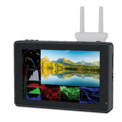
BVM-L230
Table of Contents
Manual Structure
Purpose of this manual ................................................................. 3
Related manuals ........................................................................... 3
Trademarks ................................................................................... 3
1. Service Overview
1-1. Appearance Figure ..........................................................1-1
1-2. Board Location ...............................................................1-1
1-3. Disassembly ....................................................................1-2
1-3-1. Cabinet ..................................................................1-2
1-3-2. Bottom Cabinet .....................................................1-3
1-3-3. Bezel Assembly.....................................................1-4
1-3-4. T Board/ST1 Board ...............................................1-5
1-3-5. G Board .................................................................1-6
1-3-6. B Board .................................................................1-7
1-3-7. YA Board/YB Board/YC Board ...........................1-8
1-3-8. DC Fan ..................................................................1-9
1-3-9. LCD Panel Module/T-CON Board .....................1-10
1-3-10. LMD1 Board .......................................................1-11
1-3-11. LMD2 Board .......................................................1-12
1-3-12. LCD Unit .............................................................1-13
1-4. Packing the LCD Unit ..................................................1-14
1-5. Attaching BKM-37H ....................................................1-15
1-6. Procedure when Replacing the LCD Unit ....................1-18
1-6-1. CD-R Directory ...................................................1-18
1-6-2. Data Transfer Procedure......................................1-18
1-7. Procedure for Replacing the B Board/LMD2 Board ....1-21
1-7-1. Preparation ..........................................................1-21
1-7-2. B Board Data Update ..........................................1-25
1-7-3. LMD2 Board Data Update ..................................1-29
1-8. Version Upgrade ...........................................................1-31
1-8-1. Required Equipment............................................1-31
1-8-2. About Memory Stick ...........................................1-31
1-8-3. Check of Memory Stick Data ..............................1-33
1-8-4. Software Version Upgrade
- In the case that the software version of
this unit is earlier than Ver. 1.3 ..........................1-36
1-8-5. Kernel Version Upgrade - Software version of
this unit is Ver. 1.3 or later ..................................1-37
1-8-6. Controller Kernel Version Upgrade
- Software version of this unit is earlier than
Ver. 1.3 ................................................................1-38
1-8-7. FPGA Version Upgrade
- Software version of this unit is earlier than
Ver. 1.3 ................................................................1-39
1-9. Recovery from Version Upgrade Failure .....................1-40
1-9-1. Judging Method of Version Upgrade Failure......1-40
1-9-2. Recovery Method ................................................1-41
1-9-3. Recovery Method for Kernel/FPGA Version
Upgrade Failure (this unit) ..................................1-48
1-9-4. Recovery Method for Kernel Version Upgrade
Failure (controller) ..............................................1-50
1-10. Uniformity Adjustment.................................................1-52
1-10-1. Uniformity Adj Menu..........................................1-52
1-11. Backlight Menu ............................................................1-53
1-11-1. SYSTEM .............................................................1-53
1-11-2. LED_DRIVE etc .................................................1-54
1-11-3. SENSOR..............................................................1-55
1-11-4. ERROR................................................................1-57
1-12. Maintenance Menu .......................................................1-58
1-12-1. Software Version Up
- Software version of this unit is earlier than
Ver. 1.3 ................................................................1-59
1-12-2. Restore Factory Set All .......................................1-59
1-12-3. Restore System Data ...........................................1-59
1-12-4. 1035/60I Mode ....................................................1-60
1-12-5. Low Latency........................................................1-60
1-12-6. Main Board..........................................................1-60
1-12-7. Backlight .............................................................1-60
1-12-8. Uniformity Adj ....................................................1-61
1-13. Lead-free Solder ...........................................................1-61
1-14. About LCD Unit/T-CON Board ...................................1-61
2. Circuit Description
2-1. G Board...........................................................................2-1
2-1-1. Operation during Power-on Sequence...................2-1
2-1-2. Circuit Operation...................................................2-1
2-1-3. Overvoltage Protection Circuit and Overcurrent
Protection Circuit ..................................................2-3
2-2. LMD1 Board...................................................................2-4
2-2-1. Green LED Power Block.......................................2-5
2-2-2. Blue LED Power Block.........................................2-5
2-2-3. Way to Change G_OUT and B_OUT Voltages ....2-5
2-2-4. ON/OFF Control of Green and
Blue LED Power Supplies.....................................2-6
