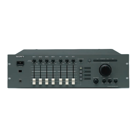
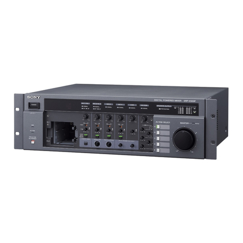
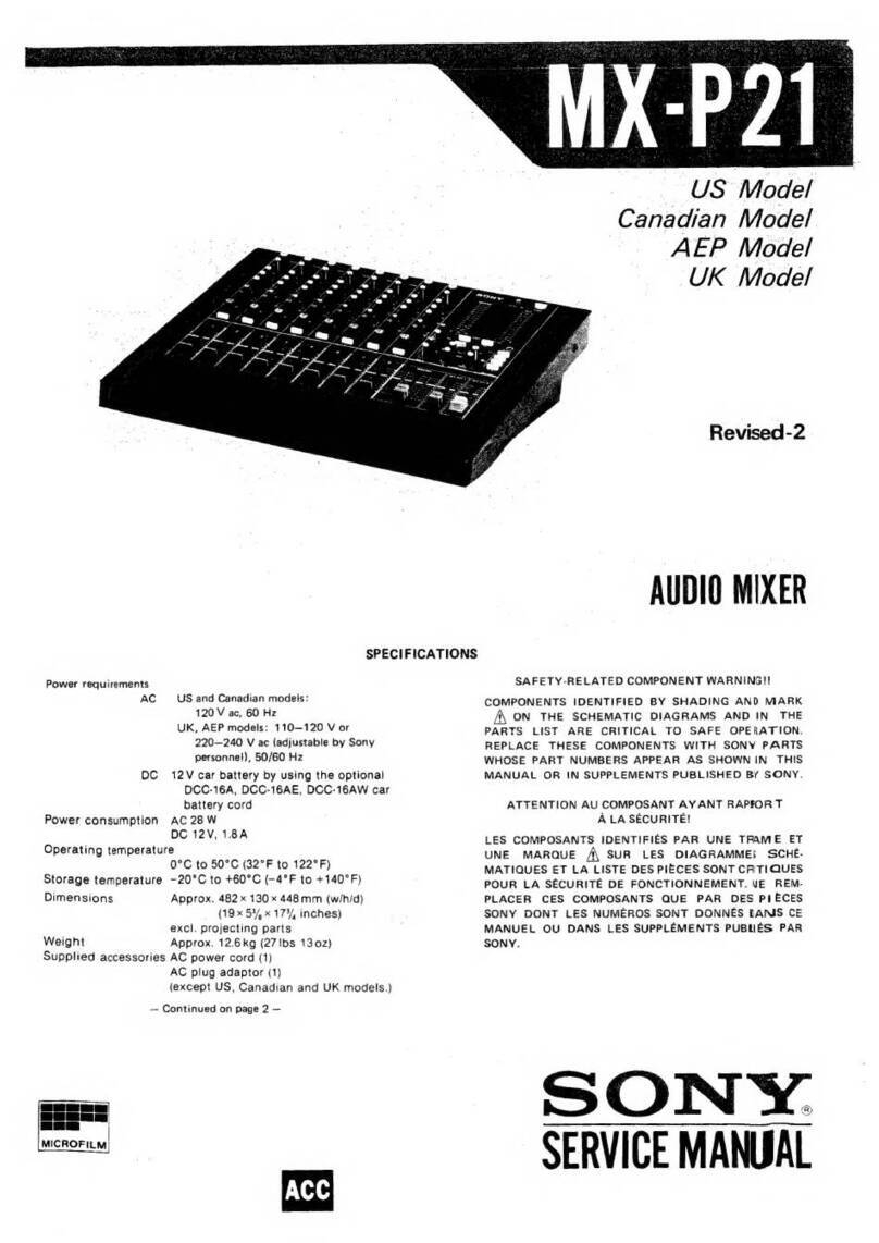
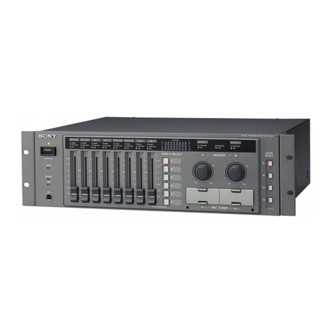
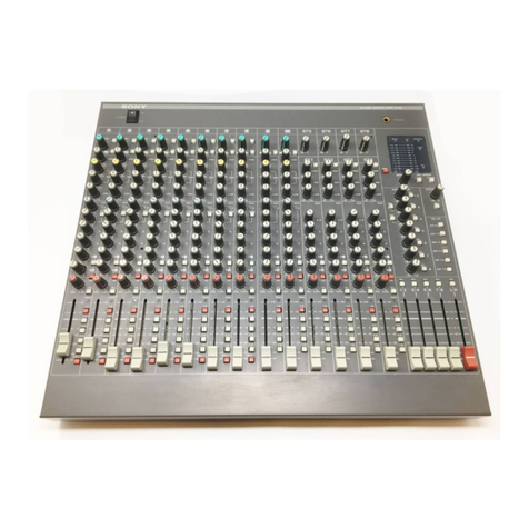
Sony SRP-X100 User manual

1
SRP-X100
Operating Instructions
AUDIOMIXER
2-347-304-12 (1)
Table of Contents
WARNING ..................................
Precautions ...............................
Features .....................................
Location and function of parts ...
Block Diagrams.........................
Specifications............................
Dimensions................................
Troubleshooting........................
2
4
4
5
7
8
8
9
Thank you for purchasing a Sony Audio Mixer. Before
operating, please read this manual carefully. Be sure to keep it
properly for future reference.
2003 Sony Corporation

2
WARNING
English
WARNING
To prevent fire or shock hazard, do not expose the unit to rain
or moisture.
To avoid electrical shock, do not open the cabinet. Refer
servicing to qualified personnel only.
Français
AVERTISSEMENT
Afin d’éviter tout risque d’incendie ou d’électrocution, ne pas
exposer l’appareil à la pluie ou à l’humidité.
Afin d’écarter tout risque d’électrocution, garder le coffret
fermé. Ne confier l’entretien de l’appareil qu’à un personnel
qualifié.
Español
ADVERTENCIA
Para evitar incendios o el riesgo de electrocución, no exponga
la unidad a la lluvia ni a la humedad.
Para evitar descargas eléctricas, no abra la caja. En caso de
avería solicite los servicios de personal cualificado solamente.
Deutsch
VORSICHT
Um die Feuergefahr und die Gefahr eines elektrischen Schlages
zu vermeiden, darf das Gerät weder Regen noch Feuchtigkeit
ausgesetzt werden.
Um einen elektrischen Schlag zu vermeiden, darf das Gehäuse
nicht geöffnet werden. Überlassen Sie Wartungsarbeiten stets
nur einem Fachmann.
Nederlands
WAARSCHUWING
Stel het apparaat niet bloot aan regen of vocht, om gevaar van
brand of een elektrische schok te voorkomen.
Open niet de behuizing, om gevaar van elektrische shokken te
vermijden. Laat reparatiles aan de erkende vakhandel over.
Svenska
VARNING
Utsätt inte apparaten för regn och fukt för att undvika riskerna
för brand och/eller elektriska stötar.
Öppna inte höljet. Det kan resultera i risk för elektriska stötar.
Överlåt allt reparations- och underhållsarbete till fackkunniga
tekniker.
Italiano
ATTENZIONE
Per evitare il pericolo di incendi o scosse elettriche,
l’apparecchio non deve essere esposto alla pioggia o all’umidià.
Per evitare scosse elettriche, non aprire l’apparecchio. Per le
riparazioni rivolgersi solo a personale qualificato.
Norsk
ADVARSEL
For å hindre brann og støtfare må enhetens overflate ikke
utsettes for regn eller fuktighet.
For å unngå elektrisk støt må kassen ikke åpnes. Service må
bare utføres av kvalifisert personell.
Suomi
VAROITUS
Tulipalon ja iskuvaaran välttämiseksi ei laitetta saa altistaa
sateelle ja kosteudelle.
Sähköiskun välttämiseksi ei koteloa saa avata. Anna vain
asiantuntijan suorittaa huolto.
Dansk
ADVARSEL
For at undgå faren for brand eller elektrisk stød må udstyret
ikke udsættes for regn eller kraftig fugt.
Åbn ikke kabinettet, da der er risiko for elektriske stød. Overlad
alle reparationer til kvalificeret servicepersonale.
Português
ADVERTÊNCIA
Para evitar o risco de incêndio ou de choques eléctricos, não
exponha o aparelho à chuva nem à humidade.
Para evitar descargas eléctricas, não abra o aparelho. Peça
assistência somente a técnicos especializados.

3
For the customers in Europe
This product with the CE marking complies with both the
EMC Directive(89/336/EEC) and the Low Voltage Directive
(73/23/EEC) issued by the Commission of the European
Community.
Compliance with these directives implies conformity to the
following European standards:
•EN60065 :Product Safety
•EN55103-1:Electromagnetic Interference(Emission)
•EN55103-2:Electromagnetic Susceptibility(Immunity)
This product is intended for use in the following
Electromagnetic Environment(s):
E1(residential),E2(commercial and light industrial),E3
(urban outdoors) and E4(controlled EMC environment ex.
TV studio).
Peak inrush current
(1)Power ON,current probe method: 1A (240V)
(2)Hot switching inrush current, measured in
accordance with European
standard EN55103-1: 1A (230V)
Pour les clients européens
Ce produit portant la marque CE est conforme à la fols à la
Directive sur la compatibilité électromagnétique (EMC) (89/
336/CEE) et à la Directive sur les basses tensions (73/23/
CEE) émises par la Commission de la Communauté
européenne.
La conformité à ces directives implique la conformité aux
normes européennes suivantes:
•EN60065 :Sécurité des produits
•EN55103-1:Interférences électromagnétiques (émission)
•EN55103-2:Sensibilité électromagnétique (immunité)
Ce produit est prévu pour être utilisé dans les
environnements électromagnétiques suivants:
E1(résidentiel),E2(commercial et lndustrie légère),E3
(urbain extérieur) et E4(environnement EMC contrôlé ex.
studio de télévision).
Appel de courant de créte
(1)Mise sous tension (ON), méthode de sondago
du courant: 1A (240V)
(2)Mesuré conformément à la norme européenne
EN55103-1: 1A (230V)
Für Kunden in Europa
Dieses Produkt besitzt die CE-Kennzeichnung und erfüllt
sowohl die EMV-Direktive (89/336/EEC) als auch die
Dilevtive Niederspannung (73/23/EEC) der EG-Kommission.
Die Erfüllung dieser Direktiven bedeutet Konformität für die
folgenden Europäischen Normen:
•EN60065 :Produktsicherheit
•EN55103-1:Elektromagnetische Interferenz(Emission)
•EN55103-2:Elektromagnetische Empfindlichkeit(Immunität)
Dieses Produkt ist für den Einsatz unter folgenden
elektromagnetischen Bedingungen ausgelegt:
E1(Wohnbereich),E2(kommerzleller und in beschränktem
Maße industrieller Bereich),E3(Stadtbereich im Freien) und
E4(kontrollierter EMV-Bereich, z.B. Fernsehstudio).
Spitzenstrom
(1)Einschaltstrom, Stromsonde: 1A (240V)
(2)Gemossen in EN55103-1: 1A (230V)
Notice for the Customers in the United Kingdom
WARNING:
THIS APPARATUS MUST BE EARTHED
IMPORTANT
The wires in this mains lead are coloured in accordance
with the following code:
Green-and-yellow : Earth
Blue : Neutral
Brown : Live
As the colours of the wires in the mains lead of this appara-
tus may not correspond with the coloured markings
identifying the terminals in your plug, proceed as follows:
The wire which is coloured green-and-yellow must be
connected to the terminal in the plug which is marked by
the letter E or by the safety earth symbol Yor coloured
green or green-and-yellow. The wire which is coloured blue
must be connected to the terminal which is marked with the
letter N or coloured black. The wire which is coloured
brown must be connected to the terminal which is marked
with the letter L or coloured red.
A fin d’écarter tout risque d’électrocution, garder le coffret
fermé. Ne confier l’entretien de l’appareil qu’à un personnel
qualifié.
Per evitare scosse elettriche, non aprire l’apparecchio. Per le
riparazioni rivolgersi solo a personale qualificato.
Para evitar descargas eléctricas, no abra la caja. En caso de
avería solicite los servicios de personal cualificado
solamente.
WARNING: THIS WARNING IS APPLICABLE
FOR OTHER COUNTRIES.
1 Use the approved Power Cord/Plug with carthing-contacts that
conforms to the safety regulations of each country if applicable.
2 Use the Power Code/Plug conforming to the proper ratings
(Voltage, Ampere).

4
Features
The SRP-X100 is a 1U audio mixer having a 6 channel
monaural input, and 3 channel stereo input.
This mixer is ideal as a public address (PA) mixer in small-
scale halls such as civic and banquet halls, and in schools,
AV systems in offices, etc.
6 channel Monaural Inputs
A 6 channel monaural input (XLR jack) for microphone
level inputs is provided.
Supplies power (+48V DC) to condensor microphones with
just one setting.
Input level selector buttons (for 3 - 6 channels) on rear
panel can also be used for stereo input (+4dBu) at line
level.
3 channel Stereo Inputs
Phono jack stereo inputs (-10dBu) for 3 channels are
provided.
A dedicated input connector(ST3) for recorders is provided
to prevent self-oscillation due to feedback from its own
signal.
The REC bus is isolated to prevent self-oscillation due to
feedback from the original signal.
Plentiful Output connectors
Compatible with many systems thanks to Plentiful outputs
including MASTER OUTPUT, SUB OUTPUT and REC
OUTPUT.
All Channels are equipment with Signal Indicators and
the MASTER OUTPUT is equipment a Peak Indicator.
Easy Mounting into 19’EIA Standard Rack.
Precautions
On safety
•Check that the voltage selector on the rear panel is set to
the local power line voltage. If not, set the selector to the
correct position using a screwdriver before connecting the
AC power cord to a wall outlet.
•This set includes 2 types of AC power cords.
Please select the one that is suitable for the region that
your are living in.
•Should any liquid or solid object fall into the cabinet,
unplug the unit and have it checked by qualified personnel
before operating it any further.
•Unplug the unit from the wall outlet if it is not to be used
for an extended period of time. To disconnect the cord,
pull it out by grasping the plug. Never pull the cord itself.
On installation
Do not install the unit in a location near heat sources such as
radiators or air ducts, or in a place subject to direct sunlight,
excessive dust, mechanical vibration or shock.
On operation
•Before making program source connections, be sure to
turn the power switch off and unplug the unit.
•When the unit is not used, turn the power off to conserve
energy and to extend the useful life of your unit.
On cleaning the cabinet
Clean the cabinet, panel and controls with a soft cloth
lightly moistened with mild detergent solution. Do not use
any type of abrasive pad, scouring powder or solvent such
as alcohol or benzine.
On repacking
Do not throw away the carton and the packing material. It
makes an ideal container for transport the unit in.
When shipping the unit for repair work or to another
location, repack it as it was.
If you have any questions or problems concerning your
unit, please contact your nearest Sony dealer.
VOLTAGE
SELECTOR
120V 230V

5
Location and function of parts
Front panel
1POWER button & Power Indicator
This turns the power to the unit on and off. Power
indicator lights up (green) when power is on.
2MONO INPUT knobs
Use to adjust the mixing level on MONO INPUT
channels 1 - 6.
3STEREO INPUT knobs
Use to adjust the mixing level on STEREO INPUT
channels 1 - 3.
The ST3 audio is output from REC OUTPUT connec-
tors.
Therefore no signal loop occurs and sounds can be
safely recorded even if the ST3 INPUT knob is still
set high during recording. (See illustration).
4MODE button
Selects how to use the MASTER OUTPUT. At
MONO (O) issues a monaural output, at STEREO
(o) issues a stereo output.
5MASTER OUTPUT knob
Use this knob to adjust the output level at the MAS-
TER OUTPUT connectors.
6SUB OUTPUT knob
Use this knob to adjust the output level at the SUB
OUTPUT connectors.
7SIGNAL indicators
This indicator lights up when input with a signal
ranging from standard input level to more than -20dB.
8+48V indicator
This indicator lights up when power (+48V DC) is
supplied to the MONO INPUT connectors.
9PEAK indicator
Warns that the output signal is too high.
The INPUT knob must be adjusted when this indica-
tor keeps lighting up. (If indicator lights up only
occasionally then there is no problem.)
SRP-X100 Recorder
OUTPUT
MASTER
Soundsignal
of
exceptST3
When
recording
ST3
REC
OUTPUT
INPUT
MIN MA
SIGNAL
1
MIN MA
SIGNAL
2
MIN MA
SIGNAL
3
MIN MA
SIGNAL
4
RLINE
MONO
L
MIN MA
SIGNAL
5
MIN MA
SIGNAL
6
MIN MA
SIGNAL
1
MIN MA
SIGNAL
2
MIN MA
SIGNAL
+48V PEAK
MODE
3
RLINEL
OFFON
POWER
STEREO
STEREO
MONO
MASTER
0
SUB
0
AIDIO MIXER SRP-X100
1 2 3
87 9
45 6

6
6MONO INPUT connectors
XLR-3-31 type. (balanced, reference input level
LINE+4dBu, MIC:-60dBu)
No.1 pin:GND No.2 pin:HOT No.3 pin:COLD
This is an input connector for the MONO INPUT
channel.
MONO 1/2 are for microphones but MONO 3 - 6
connect to either microphones or line level devices.
Set the input level selector button to LINE position
(O) when a line level output device is connected to
MONO 3 - 6.
The LCF for Fc=100Hz functions when setting the
mic level.
7INPUT LEVEL Selector buttons
These buttons switch the MONO INPUT 3-4, MONO
INPUT 5-6 input levels according to the connected
equipment.
When these buttons is set to LINE (O) to a line level
(+4dBu) input and automatically assigns Ch. 3, 5 to
the L channel, and Ch. 4, 6 to the R channel.
8+48V button
This button supplies power (+48V DC) for the
condensor microphone to MONO INPUT connectors
1 - 6.
Setting this button to ON (O), supplies +48V DC to
the MONO INPUT connectors that is set to mic level.
9AC Inlet
Attach the supplied AC power cord here.
0VOLTAGE SELECTOR
Set the VOLTAGE SELECTOR to your areas
voltage value. Please refer to P4.Precautions.
1MASTER OUTPUT connectors
XLR-3-32 type. (balanced, reference output
level:+4dBu)
No.1 pin:GND No.2 pin:HOT No.3 pin:COLD
Outputs signal from MASTER OUTPUT VOLUME.
2SEPARATE button
Pressing this button to ON (O) outputs only STEREO
INPUT signals or MONO INPUT signals that is set to
line level from the MASTER OUTPUT connector,
output only MONO INPUT signal that is set to
microphone level from SUB OUTPUT connector.
Used for separate to the line level output signals and
microphone signals.
3SUB OUTPUT connectors
Phono jack (unbalanced, reference output level:-
5dBu)
Outputs a mono-mixed signal from SUB OUTPUT
VOLUME.
Outputs the same signal from two phono jacks.
4REC OUTPUT connectors
Phono jack (unbalanced, reference output level:-
10dBu)
Outputs the signal not passing through MASTER
OUTPUT VOLUME.
5STEREO INPUT connectors
Phono jack (unbalanced, reference output level:-
10dBu)
These are input jacks for the STEREO INPUT
channel.
ST1, 2 are usually only for playback equipment. ST3
is connected to a recording equipment wired to the
REC OUTPUT connector of this unit (SRP-X100).
Note
• Before removing cables, or using the +48V button, always
be sure to turn the MONO INPUT button all the way down.
Rear panel
Location and function of parts
3 2 1 6 5
R
MASTER OUTPUT STEREO INPUT MONO INPUT
SUB OUT REC OUT
L
L
R
LR
SEPARATE
ON
OFF
LINE
MIC
4 3 2 1
LR
LINE
MIC ~ AC IN
+48V
ON
OFF
1 34 5 6 9
278
120V
VOLTAGE
SELECTOR
230V
0

7
Block Diagrams
+48V
MONO2
-60dBu
L
R
MASTEROUTPUT
+4dBu
L
R
L
R
RECOUTPUT
-10dBu
SUBOUTPUT
-5dBu
RECL
RECR
MASTERL
MASTERR
LCF CHANNEL
VOLUME
CHANNEL
VOLUME
SameasST1
MONO1
-60dBu
MASTEROUTPUT
VOLUME
MICHA
Signal
IND
Signal
IND
MODE
SWITCH
SameasMONO1
MONO3
-60dBu/+4dBu
MONO
STL
STR
SEPARATE
SWITCH
LCF
CHANNEL
VOLUME
LCF
CHANNEL
VOLUME
MICHA
Signal
IND
SameasMONO3
SameasMONO4
MONO4
-60dBu/+4dBu
MONO5
-60dBu/+4dBu
+48V
MICHA
+48V
PEAK
SUBOUTPUT
VOLUME
MIC
SameasST1
Signal
IND
fc=100Hz
fc=100Hz
fc=100Hz
ST3
-10dBu
MIC/LINE
SWITCH
STEREO
MONO
MONO6
-60dBu/+4dBu
ST1
-10dBu
ST2
-10dBu
(O)
(o)
→
→

8
Specifications
Item Conditions Standard
Frequency response 20Hz to 20kHz, 1kHz fundamental, MASTER OUT +0.5dB/-1dB
(LINE/STEREO-IN) 5Hz to 100kHz, 1kHz fundamental, MASTER OUT +0.5dB/-2dB
Total harmonic distortion (T.H.D.) MONO IN-MASTER OUT, 1kHz -44dBu input less than 0.01%
STEREO IN-MASTER OUT, 1kHz +4dBu input less than 0.005%
STEREO IN-MASTER OUT, 1kHz -10dBu input less than 0.005%
Residual noise level ch fader: –∞MASTER VOL : 0 MASTER OUT IHF-A less than -83dBu
Equivalent input noise MONO IN input terminated at 150ΩIHF-A less than -126dBu
Crosstalk 1kHz across L-R less than -70dB
1kHz across channels less than -80dB
1kHz MAX-MIN (ch fader) more than 90dB
INPUTS/OUTPUTS
Connector Connector type
Channel
Reference I/O Level Max I/O Level I/O Impedance
MONO IN*1 XLR3-31 6 MIC: -60dBu MIC: -30dBu MIC: more than 2.2kΩ
LINE: +4dBu LINE: +24dBu LINE: more than 10kΩ
STEREO IN PHONO 3(Stereo) -10dBu +10dBu more than 47kΩ
REC OUT PHONO 1(Stereo) -10dBu +10dBu less than 470kΩ
SUB OUT PHONO 2 -5dBu +15dBu less than 470kΩ
MASTER OUT XLR3-32 1(Stereo) +4dBu +24dBu less than 47Ω
OTHERS
+48 V Power supply MONO 1 - 6 jacks (MONO 3 - 6 are only during Mic level settings)
Power requirements AC 120/230V (switch selectable) 50/60Hz
Power consumption 19W
Dimensions 482 x 44 x 175 mm(width/height/depth)
not including max protrusion
Mass 2.6kg
Operating temp. 0°C to 40°C
Storage temp. -20°C to 60°C
Suplied accessories Operating instructions (1)
EURO type AC power cord (1)
US type AC power cord (1)
Design and specifications are subject to change without notice.
0dΒu = 0.755V
Unit;mm
MIN MA
SIGNAL
1
MIN MA
SIGNAL
2
MIN MA
SIGNAL
3
MIN MA
SIGNAL
4
RLINE
MONO
L
MIN MA
SIGNAL
5
MIN MA
SIGNAL
6
MIN MA
SIGNAL
1
MIN MA
SIGNAL
2
MIN MA
SIGNAL
+48V PEAK
MODE
3
RLINEL
OFFON
POWER
STEREO
STEREO
MONO
MASTER
0
SUB
0
AIDIO MIXER SRP-X100
3 2 1 6 5
R
MASTER OUTPUT STEREO INPUT MONO INPUT
SUB OUT REC OUT
L
L
R
LR
SEPARATE
ON
OFF
LINE
MIC
4 3 2 1
LR
LINE
MIC
~ AC IN
+48V 120V
VOLTAGE
SELECTOR
230V
ON
OFF
482
340
430
446
175
12525
16 7
Dimensions
*1 MONO 1 - 2 : MIC level only
MONO 3 - 6 : MIC level or LINE level selectable

9
Power will not turned on. Has AC power cord been pulled out?
No sound. •Is INPUT knob set to MIN?
•Is OUTPUT knob set to –∞?
No sound from microphone. Was INPUT LEVEL Selector button mistakenly set to LINE (instead of
MIC) for microphones connected to MONO 3 - 6. (page 6)
•No microphone audio from MASTER OUTPUT. Was SEPARATE button set to ON (O)? (page 6)
•No audio from equipment connected to lene
level - stereo system from SUB OUTPUT.
No ST3 input audio from REC OUTPUT. Signal from ST3 does not output to REC OUTPUT. (page 5)
Audio does not sound like stereo. Is the MODE button set to STEREO? (page 5)
Sound is distorted. •Is PEAK indicator lighting up? (page 5)
•Was INPUT LEVEL Selector button set to MIC (instead of LINE) for
line equipment connected to MONO 3 - 6. ?(page 6)
Troubleshooting

10 Printed in Japan
Other manuals for SRP-X100
3
Table of contents
Other Sony Music Mixer manuals