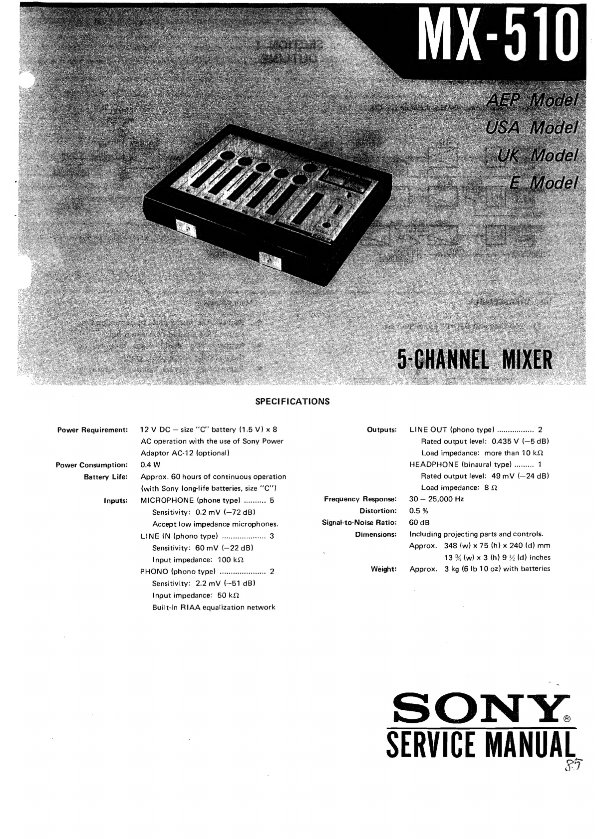
Sony MX-510 User manual

Power
Requirement:
Power
Consumption:
Battery
Life:
Inputs:
SPECIFICATIONS
12
V
DC
—
size
“C"'
battery
(1.5
V)x
8
AC
operation
with
the
use
of
Sony
Power
Adaptor
AC-12
(optional)
0.4
W
Approx.
60
hours
of
continuous
operation
(with
Sony
long-life
batteries,
size
‘‘C’’)
MICROPHONE
(phone
type)
..........
5
Sensitivity:
0.2
mV
(—72
dB)
Accept
low
impedance
microphones.
LINE
§N
(phono
type)
.........
eee
8
Sensitivity:
60
mV
(—22
dB)
Input
impedance:
100
kQ
PHONO
(phono
type)
.......ccecceeecenee
2
Sensitivity:
2.2
mV
{(—51
dB)
Input
impedance:
50k
Built-in
RIAA
equalization
network
Outputs:
Frequency
Response:
Distortion:
Signal-to-Noise
Ratio:
Dimensions:
Weight:
LINE
OUT
(phono
type)
.......
ee
2
Rated
output
level:
0.435
V
(—5
dB)
Load
impedance:
more
than
10
kQ
HEADPHONE
(binaural
type)
.
no
Rated
output
level:
49
mV
(—24
dB)
Load
impedance:
8
Q
30
—
25,000
Hz
0.5
%
60
dB
Including
projecting
parts
and
controls.
Approx.
348
{w)
x
75
(h)
x
240
(d)
mm
13
%
(w)
x
3
(h)
9
%
(d)
inches
Approx.
3
kg
(6
ib
10
oz)
with
batteries
SON
Y.
SERVICE
MANUAL
&
7

MX-510
SECTION
1
OUTLINE
1-1.
BLOCK
DIAGRAM
Note:
L-CH
is
shown.
R-CH
is
the
same
as
L-CH.
;
LEVEL
GAIN
MASTER
Q101
CONTROL
102
MICROPHONE
fart]
R124
z(t}
—}
>}
—
ATT
ee
.
Zz
|
.
ee
NPUT
VRiot
Riv?
|
SELECT
5
INE
ING
UNE
IN
INPUT
—
Q301
A
SE
MICROPHONE
far
-
PHONO
/
HEADPHONE
©)
LINE
QUT
LINE
ING
i
ENROL
TO
R-CH
1-2.
DISASSEMBLY
—
Main
Chassis
—
@
Remove
the
shield
plate
by
removing
two
screws
PS
3
x
6
and
two
solder
lugs.
@
Remove
two
shield
plate
supports
as
shown
in
the
above
photograph.
\
pull
1)
Top
Case
and
Battery
Lid
Removals
@
Remove
the
carrying
handle
by
removing
two
screws
B
4
x
20.
bottom
case
battery
lid
or
or
main
case
top
case
2)
Bottom
Case
and
Main
Chassis
Removals
—
Bottom
Case
—
First,
remove
the
battery
lid
and
batteries
and
remove
four
screws
B
3
x
8
which
secures
the
bottom
case.
B3x8
7.
B3x8
shield
plate
shield
plate
support
support
B3x8
B3x8

MX-510
SECTION
2
ADJUSTMENTS
VR103
VR203
VR601
(L-CH)
[(R-CH)
1.
LEVEL
METER
CALIBRATION
2
BATT
CHECK
ADJUSTMENT
Setting:
Setting:
Power
source:
12VDC
Power
source:
external
8.8
V
DC
MASTER
control:
maximum
BATT
CHECK
switch:
pushed
MIC-ATT-LINE
IN
switch:
MIC
POWER
switch:
ON
POWER
switch:
ON
Procedure:
een
ere
power
supply
af
osc
t)
attenuator
O
Ai
Oe
DCIN12V
14-O0OO0
aa
ee,
60082
mye1,2
LINE
OUT
7
1
kHz,
—60
dB
(0.77
mV}
_
—5
dB
(0.435
V}
Adjust
VR60I1
to
obtain
O
dB
indication
on
the
VU
R
meter.
l.
Adjust
GAIN
control
to
obtain
—5 dB
(0.435
V)
at
LINE
OUT.
a
Adjust
VR103
and
VR203
to
obtain
0
dB
indication
on
the
VU
meters.

MX-510

MX-510
MX-510
SECTION
2
ADJUSTMENTS
ad
IRS
A
eg
EEE
ad
A
oi
a
Sr
Fe
ae
WU
Pina
Ea!
Sti
ig
pa
a
Dl
ies
VR103
VR203
VR6OT
{L-CH})
{R-CH}
1,
LEVEL
METER
CALIBRATION
2.
BATT
CHECK
ADJUSTMENT
Setting:
Setting:
Power
source:
12
VDC
Power
source:
external
8.8
V
DC
MASTER
control:
maximum
BATT
CHECK
switch:
pushed
MIC-ATT-LINE
IN
switch:
MIC
POWER
switch:
POWER
switch:
ON
Procedure:
external
DC
power
supply
af
osc
attenuator
DCIN12V
60082
Mic1,2
LINE
OUT
:
1
kHz,
—60
dB
(0.77
mV}
~—5
dB
(0.435
V)
Adjust
VR601
to
obtain
O
dB
indication
on
the
VU
R
meter.
Le
Adjust
GAIN
control
to
obtain
—5dB
(0.435
V)
at
LINE
OUT.
2.
Adjust
VR103
and
VR203
to
obtain
0
dB
indication
on
the
VU
meters.

31.
MOUNTING
DIAGRAM
—
Conductor
Side
—
Q707,
102,
104,
201,
202,
204,
301,
302,
407,
402,
501,
502
2SC637A
Q705,
106,
107,
205,
206,
207
503,
607
2SCE33A
D107,
102,
201,
202
1722
cathode
anode
D601:
10D-05
cathode
SECTION
3
DIAGRAMS
Q205
Q204
Q206
Q207
D202
D201
KPAN
POT
BOARDJ
LINE
OUT
J203
ad
$202
BATT
CHECK
WHT/RED
é
em
o|]
|
Ie
of
gy
St:
%
eaiiatesse
een
RGR
se
HEADPHONE
BLU
MA-510
MX-510
QI06
sol
QI07 Ql04
DIO!
Qios5
MEIOI
LEVEL
METER
(L)
J501
MIC.
5(PAN
POT)
J502
LINE
IN
WHT/BRN
Q40i
Q502
5(PAN
POT)
Q503
J401
MIC
4(R)
perk
2
S40h
LNPUT
SEL
WHT/BRN
D60I
J402
PHONO
4(R)
Bes
BLK
BRN
CNJ6O!
OC
IN
lav
Q30!
Q402
Qé60l
J301
MIC
3(L)
——
eae
WHT/RED
BLK
J201
MIC
2(R)
shyness
nhs
‘RY
rare
ear
eS
SS
ox
Sacre
een
Dn
ste
K
AUDIO
JIOl
MIC
HL)
s
siof
op
Syeda
NPUT
SELECT
AMP
BOARD]
Jl02
LINE
IN

|
avizvi
w
6
ww
Visi
wW
£
Ww
|
.
Note:
ae
regen
ea
oO
All
capacitors
are
in
uF
unless
otherwise
noted.
ARO
50
or
less
working
volts
are
omitted
except
for
CAMP
BO
1
SSS
|
ED
SES
———
=
SE
—_
electrolytic
type.
p
=
Bur
L-CH
a
“~~
noted.
k
=
1,000,
M
=
1,000
k
clo2
oe
o
(N)
indicates
a
low-noise
resistor.
|
lO/I6V
o
Voltages
are
DC
with
respect
to
ground
unless
BTC
ROPRONE
PUT
RIO3
‘oon
*
ClO6
silt
Qi04
Q105
Q106
QI07
otherwise
noted.
Readings
taken
under
no-
i(L)
ac
any.
b72V
Bt
SSCeviN)
eel
iia
2SC6SIA
ene
ee
eneoren
EOCESIA
signal
conditions
with
a
VOM
(20
k&Q/V).
|
=a
o
Voltage
variations
may
be
noted
due
to
normal
0
*
O
DIOL.
102
IT22
production
tolerances.
-7208
18k
(LOW)
sual
tt
©
Switch
Mode:
20k(A)
J102
RU5
590k
CONTRO
LINE
IN
1(L)
a
10
|
6—
~22dB
(l100kQ)
r
en
ee
a
ee
Ne
te
wk
a
eh
ea
og
ee,
i
eee
J201
|
MICROPHONE
2
(R)
:
5]
|
e
SAME
AS
L-CH
R224
I8k
|
=e
°
REFERENCE
NO.
STARTS
FROM
|
if
4
|
201
|
6
|
|
J202
|
LINEIN
2(R)
8
124
4.7/25V
VRIO3
METER
Ok
ADYJ
DIOL
37
C)
RI39
Cl23
15k
47/i0V
ry
e
SAME
AS
L—CH
|
4(R)
R424
|8k
|
Ret
No.
Switch
Position
$101
~
501;
INPUT
SELECT
|
MIC
$202
BATT
CHECK
|
OFF
(LEVEL)
$601
POWER
OFF
®
MEIOL
LEVEL
METER
|
|
34
R136
J103
O}
vet
100k
LINE
OUT
FF
ey
a
pe
eee
ee
a
i
O)
(L)
c301
Q30I
2SC63IA
33
~5dB
47/\6V
(100KN
LOAD)
Cr
9.3V
R308
1.2k
|
|
[
sige
C302
10/16V
S301B
C
|
HEADPHONE
QV
INPUT
SELECT
Re
eee
MASTER
4;
0
J
301
i
R305
R314
12k
MIC
°
O
MICROPHONE
F300
S
100k
|
=y—-+
3(L
|
~24dB
|
prev
ae
|
(80.
LOAD)
©
)
|
“7248.
—SC«O
Sk
|
(LOW)
4.7/25V
GO
eee
ee
et
oe ae
ee
ee
gt
ee
8
pe
le
ee
(N)
C307
R318
|
43
J
PHONO
3(L)
80k
|
MP
eienika:
aA
]
:
=
|
¢
REFERENCE
NO.
STARTS
Ro
dl
|
FROM
C213,
R225,
0204,
O
T
|
VR203,
D201
and
T201
—510B
R317
220k
:
(50k)
a
aa
ee
ge
ee
a
te
ee
ee
es,
ee
aye
eet
eee
7
|
R-CH
|
|
J40l
l
|
MICROPHONE
r
|
|
2
.
AG
ERENCE
NO.
STARTS
FROM
J402
PHONO
4(R)
a
ah
a
I
J
C50)
47/\6V
ee
ee
Q60I
2SC633A
—DGOI
10-05
NEZOI
lO/I6V
LEVEL
METER:
BATT
CHECK
ADJ
Joo
fa
wet
MICROPHONE
SELECT
R503
SELECT
R602
“VR6O1
S(PAN
POT)
17
C.
MIC
47k
47k
[ee
R50)Jart,
D6OI
oan
--72dB
O
(LOW)
POWER
O7
7
7
J502
“0
ra
}----1
LINE
IN
Foe
et
BATT
SIZE°C"
8x5
9
5(PAN
POT)
qooKa)
.
—
—-
8g—
CNJSOI
;
|
-,
DC
IN
l2V
Se
100k
_Q50
502
2SC63IA
Q503
2SC633A
O
Q50!_2SC63IA
Q
Q
CPAN
POT
BOARD]

MX-510 MX-510
SECTION
4
EXPLODED
VIEWS
toe
ret
Bue
1.520-224-11
Meter,
fevel
(ME107)}
41.
:
4-2.
3-5.36-8
14-00
Knob,
GAIN
CONTROL
1-520-224-21
Meter,
fevel
(ME201)
1-224-375-00
Resistor,
variable;
20k
(8);
PAN
POT
(VR502}
X-2218-002-0
Cover
Ass’y
X-22
18-001-0
;
Bracket
Ass’y,
rotary
switch
PS3x6
Supplied
with
eS)
switch
‘
2-248-016-00
pa
:
Pan
Pot
Board
Cushion,
meter
2-202-6
12-02
FF
i}
—
2-218-01
1-00
;
Bracket,
variable
resistor
PS
3x6
("3
2-218-015-00
Bracket,
meter
e2
eo4
2-218-003-00
2-202-6
13-00
Cover,
variable
resistor
Stopper,
cursor
2-218-018-00
X-22
18-004-0
Button,
switch
2-203-943-00
Case
Ass’y,
upper,
Handle
SE
including
parts
marked
@
7-5
ze
S
<
—
PS2x5
2-218-017-00
Holder,
switch
1-576-4177-XX
pa!
Switch,
push;
BATT
CHECK
2-218-002-00
($202)
2-218-021-00
~
Emblem,
SONY
Stopper,
hand/e
2-098-862-0
ie
por
2-203-947-00
7
.
oe
Screw
Terminal
84x20
—
2.218-010-00
Supplied
with
jack
rrr
22026
14-00
Bracket,
handle
,
Washer,
ground
Pring,
Cursor
stopper
2.218-019-00
4.812-134-00
»
2-218-07
3-00
:
f
r
Tape
Panel,
jack
D
a
Rivet,
plastic
{
,
ee.
ail
e
;
Bs)
fa
ee
2-070-638-00
'
Spacer,
jack
—
«3
Z
a
ee
eae
#
3-425-055-00
Oy,
bbs
pitas
ae
2-218-024-00
Sp
Terminal,
battery
positive
Stud,
shield
plate
re
BZ
7
)
4
Jock
phone:
MICROPHONE
ae
94-00
.218-0142-
lack,
phone;
MiICROP
1-516-194-
tes
ane
(S101
~
507)
Switch,
rotary;
INPUT
‘
SELECT
(S101
~
501)
ee
Jack,
DC
IN
12
V
(CNJ6O1)
Supplied
with
jack
és
2-218-014-00
Bracket,
switch
2-218-009-00
Angle,
right
|
1-507-476-XX
Jack,
binaural,
HEADPHONE
(104)
2-218-008-00
2-218-020-00
Angle,
left
Case,
lower
mss
3
—~
Ta
5
1-507-176-XX
Jack,
phono,
LINE
tN/
LINE
OUT
(102
~
502,
103,
:
203)
|
PS
2-218-033-00
(E
model}
2-21
8-034-00
(USA
model}
Lavel,
specification
sae
ey
|
!
TZ
Cf
Sx
SZ
Gi
1-514-655-XX
Ze
SA
!
Switch,
rocker;
POWER
(S601)
1-224-230-00
i
Resistor,
variable;
20
KQ
(Aj;
>
|
Ja
2-218-023-00
Spring,
battery
negative
X-2218-003-0
Case
Ass’y,
battery
GAIN
CONTROL
(VR101
~
501)
Audio
Amp
Board
3-426-449-00
1-224-231-00
Foot,
rubber
Resistor,
variable;
20
k&.
(A);
lass
Note:
MASTER
(VR102,
202)
ita:
o
Items
with
no
part
number
and/or
no
o
Items
with
no
part
number
and/or
no
description
are
not
stocked because
they
description
are
not
stocked
because
they
-
.
abe
peudemn
Weduied,
20m
Eevee,
Zone
are
seldom
required
for
routine
service.
o
All
screws
are
Phillips
(cross
recess)
type
o
All
screws
are
Phillips
(cross
recess)
type
unless
otherwise
noted.
unless
otherwise
noted.
(—)
=
slotted
head
(—)
=
slotted
head
ree
|
lO

Ref.
No.
Q101
~
501
202
~
502
104,
204
Q105
~
107
205
~
207
503,
601
D101,
102
201,-202
D601
C101
~
501
C102
~
502
C103
~
503
C105
~
505
C106
~
506
C107
~
507
C108
~408
C109
~
509
C110
~510
Clli~411
C113,
213
C114,
214
C1i5;.215
C116,
216
C117,
217
C118,
218
C119.219
C120,
220
Cl21,-221
C122,
222
ELECTRICAL
PARTS
LIST
Part
No.
SEMICONDUCTORS
Transistors
Q101
~
501:
Q101,
201,
301.....
,
Q501
28C631A
28C633A
Diodes
1T22
10D-05
CAPACITORS
All
capacitors
are
in
uF
and
of
electrolytic
unless
otherwise
noted.
(p
=
uuF)
50
or
less
working
volts
are
omitted
except
for
electrolytic
type.
Description
C101
~
501:
C101,
201,
301.....
,C501
1-121-409-1147
16V
1-121-651-11
10
16V
1-121-915-11
4.7
25V
1-107-139-11
220p
(-120-913-11.
33
25V
1-107-119-11
33p
1-121-391-11
1
50V
1-121-651-1110
16V
1-107-139-11
220p
1-121-651-11
10
16V
1-121-404-1133
25V
1-121-395-1147
25V
1-107-139-11
220p
1-107-115-11
22p
1-121-651-11
10
16V
1-121-352-11
47
10V
1-121-391-1111
50V
1-121-726-11
0.47
50V
1-107-124-11
5lp
1-121-479-1122
16V
SECTION
5
low
noise
silvered
mica
low
noise
silvered
mica
silvered
mica
silvered
mica
silvered
mica
silvered
mica
MX-510
Ref.
No.
Part
No.
Description
C123,
223
1-121-352-11
47
10V
C124,
224
(1-121-395-11
4.7
25V
C125,
225
1-121-651-11
10
16V
C312,
412
1-106-049-12
0.1
mylar
C313,
413
1-106-041-12
0.047
my
lar
C508
1-121-726-11
0.47
50V
C511
1-121-391-11
1
50V
C512
1-121-404-11
33
25V
C601
1-119-140-11
2200
16V
C602
1-121-426-11
470
16V
C603
1-106-082-12
0.01
my
lar
RESISTORS
All
resistors
are
in
ohms.
Regular
type
¥%W
corbon
and
composition
resistors
are
omitted.
Check
the
schematic
diagram
for
the
resistance
Values.
(k
=
1000,
M
=
1000
k)
R103
~
503:
R103,
203,
303.....
,
R503
R102
~
503
1-24
2-7
33-11
330k
%W
carbon
low
noise
R104
~
504
1-242-725-11
150k
Y%W
carbon
low
noise
R106
~
506
1-242-693-11
6.8k
%W
carbon
low
noise
R109
~509
1-242-731-11
270k
Y%W
carbon
low
noise
R110
~510
1-242-721-11
100k
%W
carbon
low
noise
RLI2
512
1-242-697-11
10k
¥Y4,W
carbon
low
noise
R126,
226
1-242-713-11
47k
%W
carbon
low
noise
R128,
228
1-242-710-11
36k
%W
carbon
low
noise
VRI01
~501
1-224-230-00
20k
(A),
variable;
GAIN
CONTROL
VR102,
202
1-224-231-00
20k
(A),
variable;
MASTER
VR103,
203
1-224-645-XX
10k
(A),
adjustable;
level
meter
VR502
1-224-375-00
20k
(B),
variable;
PAN
POT
VR601
1-224-647-XX
47k,
adjustable;
BATT
CHECK
SWITCHS
S101
~
501:
S101,
201,
301.....
,
5501
$101
~
501
1-516-194-00
rotary,
INPUT
SELECT
$202
1-516-417-XX
push,
BATT
CHECK
S601
1-514-655-XX
rocker,
POWER

Ref.
No.
Part
No.
Description
Ref.
No.
JACKS
F101
501:
J101,
201530105620
,I501
ME101
ME201
CNJ601
1-507-447-XX
DCIN
12V
T101,
201
J101~501
1-507-480-XX
phone,
MICROPHONE
pens
1-507-176-XX
ph
LINE
IN/LINE
OUT
103,
203
ci
tied
J104
1-507-476-XX
binaural,
HEADPHONE
SECTION
6
HARDWARE
Part
No.
Description
SCREWS
All
screws
are
Phillips
(cross
recess)
type
unless
otherwise
noted.
(—):
slotted
head
7-6
28-25
3-03
PS
2x5
7-68
2-128-05
P
2x
10
7-6
82-54
8-05
B
3
x
8
7-682-5
66-04
B
4x
20
7-682-647-01
PS
3x6
7-6
82-94
7-01
PSW
3x6
MISCELLANEOUS
7-622-105-05
nut
2
7-623-205-12
spring
washer
2
7-623-508-11
earth
lug
3
Sony
Corporation
©
1975
9-954-366-01
Part
No.
Description
MISCELLANEOUS
1-520-224-11
meter,
level
1-520-224-21-
meter,
level
1-427-359-00
transformer,
output
ACCESSORIES
X-2218-005-0
cushion
ass’y
1-528-026-00
battery,
size
C,
SUM-2
1-534-049-31
cord,
RK-74
3-780-5
58-21
manual,
instruction
5H0469-1
Printed
in
Japan
Table of contents
Other Sony Music Mixer manuals

Sony
Sony XV-C700 User manual

Sony
Sony Anycast station AWS-G500 User manual

Sony
Sony PLAYSTATION VR User manual

Sony
Sony Outdoor Storage User manual

Sony
Sony SRP-X700P User manual

Sony
Sony MX-P21 User manual

Sony
Sony SRP-X500P User manual

Sony
Sony OXFORD User manual

Sony
Sony SRP-X100 User manual

Sony
Sony MXP-310 User manual