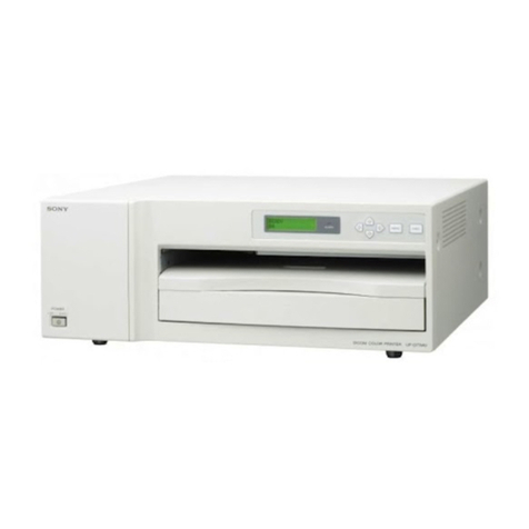
Sony UP-960 User manual

VIDEO GRAPHIC PRINTER
UP-960
UP-960CE
1st Edition
SERVICE MANUAL

!WARNING
This manual is intended for qualified service personnel
only.
To reduce the risk of electric shock, fire or injury, do not
perform any servicing other than that contained in the
operating instructions unless you are qualified to do
so. Refer all servicing to qualified service personnel.

1
UP-960(UC)
UP-960CE(CE)
TABLE OF CONTENTS
1. OPERATING INSTRUCTIONS
2. SERVICE OVERVIEW
2-1. PC BOARD LOCATION............................................................................... 2-1
2-2. REMOVAL OF THE COVER AND THE PANELS .................................... 2-2
2-2-1. Removal of the Top Cover .....................................................................2-2
2-2-2. Removal of the Door Panel .................................................................... 2-2
2-2-3. Removal of the Front Panel .................................................................... 2-3
2-2-4. Removal of the Rear Panel ..................................................................... 2-3
2-3. REMOVAL OF THE MAIN PARTS ............................................................ 2-4
2-3-1. Removal of the Mechanical Block .........................................................2-4
2-3-2. Removal of the MA-91 Board and the Switching Regulator ................. 2-4
2-3-3. Removal of the Thermal Head ............................................................... 2-5
3. ELECTRICAL ALIGNMENT
3-1. TRAP ADJUSMENT ..................................................................................... 3-1
3-2. VIDEO LEVEL ADJUSTMENT................................................................... 3-2
3-3. BRIGHTNESS AND CONTRAST ADJUSTMENT .................................... 3-2
3-4. DOOR LOCK SENSOR ADJUSTMENT ..................................................... 3-3
3-5. HEAD VOLTAGE ADJUSTMENT .............................................................. 3-4
4. CIRCUIT OPERATION DESCRIPTION
4-1. VIDEO CIRCUIT........................................................................................... 4-4
4-1-1. Input Trap Filter Circuit ......................................................................... 4-4
4-1-2. Sharpness, AGC Circuit and C-SYNC Signal........................................ 4-4
4-1-3. Brightness, Contrast Control and A/D Conversion ................................ 4-4
4-2. OSCILLATOR CIRCUIT .............................................................................. 4-5
4-3. IC601 PERIPHERAL CIRCUIT .................................................................... 4-5
4-3-1. Serial Data Reading from System Control ............................................. 4-6
4-3-2. Writing to the Frame Memory................................................................ 4-6
4-3-3. Transfer from Frame Memory to Line Memory..................................... 4-6
4-3-4. Thermal Head Control and One Line Memory ...................................... 4-6
4-4. SYSTEM CONTROL SECTION .................................................................. 4-8
4-4-1. Watch of Various Keys .......................................................................... 4-8
4-4-2. Watch of Various Function Switches ..................................................... 4-8
4-4-3. Platen Motor Control .............................................................................. 4-9
4-4-4. Head Up and Down Control ................................................................... 4-9
4-4-5. Door Open and Close Control .............................................................. 4-10
4-4-6. Watch of Paper Sensor ......................................................................... 4-11
4-4-7. Watch of the Head Temperature Sensor............................................... 4-11
4-4-8. Head Fan Motor (for Head Cooling) Control....................................... 4-11
4-4-9. Analog Circuit Section Control ............................................................ 4-12
4-4-10. Gate Array IC601 Control .................................................................... 4-12

2UP-960(UC)
UP-960CE(CE)
4-5. THERMAL HEAD SECTION.....................................................................4-13
4-5-1. Structure ...............................................................................................4-13
4-5-2. Basic Operation ....................................................................................4-14
4-5-3. Stair Generation....................................................................................4-15
4-5-4. Temperature Compensation..................................................................4-15
4-5-5. Line Number Correction.......................................................................4-15
5. TROUBLESHOOTING
5-1. PRINT IS FAULTY .......................................................................................5-1
5-2. PRINT IS TOO DARK OR TOO LIGHT......................................................5-2
5-3. “PAPER SENSOR” IS OUT OF ORDER .....................................................5-3
5-4. HEAD OPERATION (UP & DOWN) IS OUT OF ORDER ........................5-4
5-5. PAPER FEEDING IS OUT OF ORDER .......................................................5-5
5-6. DOOR (OPENING & CLOSING) IS OUT OF ORDER...............................5-6
6. SEMICONDUCTOR PIN ASSIGNMENTS
SEMICONDUCTOR INDEX ........................................................................6-1
DIODE............................................................................................................6-2
LED ................................................................................................................6-2
TRANSISTOR ...............................................................................................6-2
OTHERS ........................................................................................................6-2
IC ....................................................................................................................6-3
7. SPARE PARTS
7-1. NOTES ON REPAIR PARTS........................................................................7-1
7-2. EXPLODED VIEW .......................................................................................7-2
Ornamental Block & Mechanical Block ........................................................7-2
Ornamental Block & Switching Regulator ....................................................7-3
Sub Assy, Top Chassis ...................................................................................7-4
Feeder Block...................................................................................................7-5
Chassis Block Assy, Rear...............................................................................7-6
Chassis Block & Gear ....................................................................................7-7
7-3. ELECTRICAL PARTS LIST.........................................................................7-8
8. BLOCK DIAGRAMS
OVERALL (1/2).............................................................................................8-2
OVERALL (2/2).............................................................................................8-4

3
UP-960(UC)
UP-960CE(CE)
9. PRINTED WIRING BOARDS AND SCHEMATIC DIAGRAMS
MA-91 ............................................................................................................ 9-1
KY-421 ......................................................................................................... 9-11
PTC-98 ......................................................................................................... 9-11
SE-441 .......................................................................................................... 9-11
SE-442 .......................................................................................................... 9-11
SE-485 .......................................................................................................... 9-11
SU-41............................................................................................................ 9-11
SU-42............................................................................................................ 9-11
FRAME ........................................................................................................ 9-12


1-1
UP-960(UC)
UP-960CE(CE)
SECTION 1
OPERATING INSTRUCTIONS This section is extracted
from operation manual.
UP-960
UP-960CE
1998 by Sony Corporation
Instructions for Use
Page 30
EN
3-862-477-01 (1)
Video Graphic
Printer

1-2 UP-960(UC)
UP-960CE(CE)
30
English
Owner’s Record
The model and serial numbers are located at the rear.
Record these number in the space provided below.
Refer to these numbers whenever you call upon your
Sony dealer regarding this product.
Model No.
Serial No.
WARNING
To prevent fire or shock hazard, do not expose the unit
to rain or moisture.
To avoid electrical shock, do not open the cabinet. Refer
servicing to qualified personnel only.
R1.5m
For the customers in Europe
Important safeguards/notices for use in the
medical environments
1. All the equipments connected to this unit shall be
certified according to Standard IEC601-1, IEC950,
IEC65 or other IEC/ISO Standards applicable to the
equipments.
2. When this unit is used together with other equipment
in the patient area*, the equipment shall be either
powered by an isolation transformer or connected via
an additional protective earth terminal to system
ground unless it is certified according to Standard
IEC601-1.
* Patient Area
3. The leakage current could increase when connected
to other equipment.
4 This equipment generates, uses, and can radiate
frequency energy. If it is not installed and used in
accordance with the instruction manual, it may cause
interference to other equipment. If this unit causes
interference (which can be determined by unplugging
the power cord from the unit), try these measures:
Relocate the unit with respect to the susceptible
equipment. Plug this unit and the susceptible
equipment into different branch circuit. Consult your
dealer.
Symbol on the products
This symbol indicates the equipotential
terminal which brings the various parts of a
system to the same potential.
For the customers in the U.S.A.
This equipment has been tested and found to comply
with the limits for a Class A digital device, pursuant to
Part 15 of the FCC Rules. These limits are designed to
provide reasonable protection against harmful
interference when the equipment is operated in a
commercial environment. This equipment generates,
uses, and can radiate radio frequency energy and, if not
installed and used in accordance with the instruction
manual, may cause harmful interference to radio
communications. Operation of this equipment in a
residential area is likely to cause harmful interference in
which case the user will be required to correct the
interference at his own expense.
You are cautioned that any changes or modifications not
expressly approved in this manual could void your
authority to operate this equipment.
This device requires shielded interface cables to comply
with FCC emission limits.
For the customers in Canada (for UP-960 only)
This unit has been certified according to Standard CSA
C22.2 No.601.1.
31
Table of Contents
Table of Contents
Introduction
Preparation
Operation
Others
Overview ..........................................................................32
Connection ......................................................................33
Setting the DIP Switches ................................................34
Setting the DIP Switches on the Sub Panel.................... 34
Setting the DIP Switches on the Rear Panel .................. 36
Loading Paper .................................................................39
Printing.............................................................................41
Making Printouts ............................................................ 41
Selecting the Printing Direction/Printing Size ............... 43
Adjusting the Contrast and Brightness........................... 45
Remotely Controlling the Printer ................................... 45
Precautions......................................................................46
Maintenance ................................................................... 47
Paper ................................................................................49
Specifications..................................................................50
Troubleshooting..............................................................51
Location and Function of Parts and Controls ..............52
Front ............................................................................... 52
Back................................................................................ 53
EN
English

1-3
UP-960(UC)
UP-960CE(CE)
32
Introduction
Overview
The UP-960/960CE is a monochrome video graphic printer that reproduces images
from video equipment. Large size picture can be printed out quickly and easily
using the following features:
Clear and stable print quality
• High definition, 6.4 dots/mm printing
• 256 gradations of black and white.
• Stable printouts by the temperature compensation technology
• High density printouts using the UPP-210HD printing paper.
Two ways printing direction and two printing size selectable
• The printing direction selector on the front panel enables you to print in vertical
and horizontal directions.
• The printing size control on the front panel enables you to select two kinds of
printing size.
DIP switches to optimize the printer
• You can make printouts with bottom end first or upper part of the screen first by
using the DIRECTION DIP switch.
• Aspect ratio of printouts can be set to 4:3 or 1:1 by using the ASPECT DIP
switch.
• You can change the range to be printed out by using the SCAN DIP switch.
Fast printing
• You can make a single printout in about 10 seconds
• You can make a maximum of 11 copies of the same image continuously.
Automatic video signal discrimination
The type of input video signal (EIA or CCIR) is automatically discriminated and
printed adequately; there is no need to change any switch manually.
Easy and quick paper loading
You can load paper just by opening the door panel with the OPEN/CLOSE button
and placing the paper roll.
Introduction
33
Notes
• Turn off the power to each device before making any connections.
• Connect the AC power cord last.
• Before making connections, see “Important safeguards/notices for use in the
medical environment” on page 30.
Preparation
Connection
RM-91 remote control
unit (not supllied)
a)
Preparation
FS-20 foot switch
(not supllied)
a)
to REMOTE
to video output connector
Supplied coaxial connecting
cable (BNC ˜BNC)
to VIDEO IN
Color/black and white
video monitor
Connecting cable
(not supplied)
to video input
connector
to VIDEO OUT
to AC IN
Supplied AC power cord
to wall outlet
a) Connect either the RM-91 remote control
unit or the FS-20 foot switch.
or
REMOTE
AC IN
VIDEO
IN OUT
Video equipment/
Medical equipment

1-4 UP-960(UC)
UP-960CE(CE)
34
You can set the printer to the required print mode using the DIP switches.
The printer has two kinds of DIP switches;
• DIP switch on the sub panel
You can set the print mode frequently used in daily operation easily on the sub
panel.
• DIP switches on the rear panel
You can set the print mode and printer specifications you do not need to change
settings frequently.
How to change the DIP switch setting
Before setting the DIP switches, turn the power off. Change the settings using a
small pointed tool such as a small screwdriver.
Note
ON or OFF indicated in parentheses shows the switch setting position.
Setting the DIP Switches on the Sub Panel
The factory settings are as follows.
1AGC (Automatic Gain Control) switch
Adjusts the input signal to the optimum printing level.
OFF (OFF): Normally keep this switch set to this position.
ON (ON): When the printout image appears blackish or whitish, select this
position to adjust the input signal to the optimum level.
2IMAGE switch
POSI (ON): Normally keep this switch set to this position.
NEGA (OFF): Makes negative printouts.
Setting the DIP Switches
Preparation
O
F
F 1
2
3
4
5
6
7
8
ON
OFF
NO
FUNCTION
ON
OFF
12345678
RESERVED RESERVED
ON
OFF
GAMMA
POST FEED
TONE
HARD
IMAGE
SHARPNESS
AGC
POSI SOFT
NEGA
ON
OFF
TONE TONE
35
3SHARPNESS switch
SOFT (ON): Normally keep this switch set to this position.
HARD (OFF): Obtains greater sharpness of printouts.
4, 5GAMMA switch
Sets the printing tone to one of TONE I, TONE II or TONE III.
The diagram below shows the curve of each tone for your reference.
When you set the GAMMA switch 5to the OFF position (TONE III),
TONE III is selected regardless of the setting of the GAMMA switch 4
position.
6POSTFEED switch
ON (ON): Feeds out extra blank paper once a picture has been printed.
OFF (OFF): Does not feed out extra blank paper once a picture has been
printed. To save paper by feeding only a short length of paper after printing a
picture, set to this position. You can make more printouts per roll of printing
paper, but you have to feed the paper using the FEED button and tear off the
paper by yourself.
7, 8RESERVED switches
Keep this switch set to ON.
Preparation
High
Low
Print density
0255
Gradation
TONE I
TONE II
TONE III

1-5
UP-960(UC)
UP-960CE(CE)
36
Setting the DIP Switches on the Rear Panel
The factory settings are as follows.
175Ωswitch
ON (ON): When nothing is connected to the VIDEO OUT connector, set the
switch to this position.
OFF (OFF): When a video monitor or other video equipment is connected to
the VIDEO OUT connector, set the switch to this position.
When you connect two printers to one video equipment, set the 75Ωswitch of
one of the printer to ON, and the other to OFF.
2INPUT switch
B & W (ON): When the signal to be printed is black and white, set the switch
to this position.
COLOR (OFF): When the signal is color, set the switch to this position.
Preparation
Setting the DIP Switches (Continued)
REMOTE
AC IN
VIDEO
IN OUT
ON
OFF
37
3, 4SCAN size switches
Set the printout range. The printout range is widened in the NORM, WIDE 1,
and WIDE 2 order.
NORM (Switch 3: OFF): Prints only the image displayed on the standard
screen size of the video monitor.
WIDE 1(Switch 3: ON): Prints when the signal scans beyond the edge of
the standard monitor screen.
WIDE 2 (Switch 4: OFF): To further extend the range, select this setting.
Note
If the SCAN switch 4is set to the OFF position (WIDE 2), WIDE 2 is
selected regardless of the setting of the SCAN switch 3position.
5DIRECTION switch
Selects whether the top or the bottom of the screen is to be printed first.
NORM (ON): Normally keep this switch set to this setting. Printing is done
from the bottom of the screen.
REV (OFF): Printing is started from the top of the screen.
6MEMORY switch
FRAME (ON): Normally keep this switch set to this position.
FIELD (OFF): When printing fast moving pictures (such as a ball being
thrown), the printout may blur. If this happens, set to this position. The
printout definition will be poorer, but less blurred.
Preparation
30
3
22
3
34
3
4
1
3
5
5
3
1
1357 7531
5
3
1
30
32
2
3
3
43
4
30 32
2
3
3
43
4
3
2
3
3
4
4
3
2
5
3
1
30
275
87654321
475
50
250
9
4
5
5
7
543
3
2
3
230
10
7
0
3
30
3
22
3
34
3
4
1
3
5
5
3
1
1357 7531
5
3
1
30
32
2
3
3
43
4
30 32
2
3
3
43
4
3
2
3
3
4
4
3
2
5
3
1
30
275
87654321
475
50
250
9
4
5
5
7
543
3
2
3
2
30
10
7
0
3
NORM REV
30
3
22
3
34
3
4
1
3
5
5
3
1
1357 7531
5
3
1
30
32
2
3
3
43
4
30 32
2
3
3
43
4
3
2
3
3
4
4
3
2
5
3
1
30
275
87654321
475
50
250
9
4
5
5
7
543
3
2
3
230
10
7
0
3
30
3
22
3
34
3
4
1
3
5
5
3
1
1357 7531
5
3
1
30
32
2
3
3
43
4
30 32
2
3
3
43
4
3
2
3
3
4
4
3
2
5
3
1
30
275
87654321
475
50
250
9
4
5
5
7
543
3
2
3
2
30
10
7
0
3
30
3
22
3
34
3
4
1
3
5
5
3
1
1357 7531
5
3
1
30
32
2
3
3
43
4
30 32
2
3
3
43
4
3
2
3
3
4
4
3
2
5
3
1
30
275
87654321
475
50
250
9
4
5
5
7
543
3
2
3
2
30
10
7
0
3
NORM WIDE 1 WIDE 2

1-6 UP-960(UC)
UP-960CE(CE)
38
7ASPECT switch
4:3 (ON): Normally keep this switch set to this position.
1:1 (OFF): When the aspect ratio of the video signal is 1:1, set to this
position.
The printout will be longer than a printout made at 4:3.
8INTERRUPT switch
Sets whether the PRINT button is activated to enable interruption of the
printing process and capture an image in memory.
ON (ON): Interrupts the printing under way, captures the image displayed,
and prints a new picture.
In the SMALL mode, the printer stops printing and captures the first image.
OFF (OFF): Disregards that the PRINT button is pressed during printing and
continues the printing under way.
If you press the PRINT button during printing in OFF mode, the alarm buzzer
will sound.
9MIRROR switch
NORM (ON): Normally keep this switch set to this position.
REV (OFF): Prints the right and left sides reversed (mirror image).
0RESERVED switch
Keep this switch set to ON.
Preparation
Setting the DIP Switches (Continued)
30
3
22
3
34
3
4
1
3
5
5
3
1
1357 7531
5
3
1
30
32
2
3
3
43
4
30 32
2
3
3
43
4
3
2
3
3
4
4
3
2
5
3
1
30
275
87654321
475
50
250
9
4
5
5
7
543
3
2
3
2
30
10
7
0
3
30
3
22
3
34
3
4
1
3
5
5
3
1
1357 7531
5
3
1
30
32
2
3
3
43
4
30 32
2
3
3
43
4
3
2
3
3
4
4
3
2
5
3
1
30
275
87654321
475
50
250
9
4
5
5
7
543
3
2
3
2
30
10
7
0
3
4 : 3 1 : 1
39
2
Press the OPEN/CLOSE button to open the door panel.
Loading Paper
Notes
• Do not fold the paper or touch the printing surface. Any dust on the printing
surface will result in poor printing quality.
• Use only paper made specially for the UP-960 series. (See page 49.)
1
Press the power ON/OFF switch to turn on the printer.
The buttons on the front panel will light.
Prepration
Continue to next page
m

1-7
UP-960(UC)
UP-960CE(CE)
40
3
Place the paper roll in the printer.
Place the paper with
the thermo-sensitive
side (printing side) up.
4
Insert the end of the paper end into the paper insertion slot and feed the paper
with your hand until its end comes out from the paper outlet
Note
Be sure to remove any slack in the roll when pulling out the paper.
Prepration
Loading Paper (Continued)
5
Press the OPEN/CLOSE button to close the door panel.
You can also close the door panel simply by pushing it.
Note
After loading the paper roll, press and hold down the FEED button until 15 to 20
cm (6 to 7
7
⁄
8
inches) of the
paper protrudes and tear it off by yourself.
41
Printing
Before making printouts
• Are the connections correct? (page33)
• Is the paper roll loaded properly? (page 39)
• Are the DIP switches set correctly? (page 34)
• Is the print source being input?
Making Printouts
1
Press the power ON/OFF switch to turn on the printer.
All buttons on the front panel will light.
Note
Make sure that the PAPER EMPTY indicator is not lit.
If lit, load the paper. (See page 39.)
2
Selecting the printing direction and size.
See “Selecting the Printing Direction/Printing Size”. (See page 43.)
3
Start the video source.
This operation is done using the controls of the video equipment acting as a
source.
4
When the image you want to print is on the video monitor, press the PRINT
button.
The image displayed at the instant you press the PRINT button is captured into
memory and is printed out immediately.
To interrupt printing
Press either OPEN/CLOSE or FEED button while printing. The printer stops
printing.
Operation
Operation
124
OPEN/CLOSE
button
FEED button PAPER/EMPTY
lamp

1-8 UP-960(UC)
UP-960CE(CE)
42
To stop printing and print another picture displayed on the video
monitor
To do this, the INTERRUPT setting of the DIP switches must be set to ON. (See
page 38.)
Press the PRINT button while printing or copying. The printer stops printing,
captures the new image, and starts printing of the new image.
In the SMALL mode, the printer stops printing and captures the first image.
If the printout image is blurred
A rapidly moving image may be blurred when printed. Should this occur, change
the MEMORY setting of the DIP switch to FIELD. (See page 37.)
To print in SMALL mode
Press the PRINT button twice. When you press the PRINT button once, the buzzer
sounds and the first image is captured. The printer starts printing after the PRINT
button is pressed twice.
For detailed information on SMALL mode, see “Selecting Printing Direction/
Printing Size”. (See page 43.)
Making copies of the last printout
Press the COPY button. The printer makes a copy of the last printout. The image of
the last printout is retained in the printer’s memory until you press the PRINT
button again or turn the power off.
To copy in different sizes
You can copy the last printout in different sizes.
Before pressing the COPY button, select the printing size as described in
“Selecting the printing size” (See page 43.)
Notes
• If you press the COPY button immediately after turning the power on, the alarm
buzzer will sound as nothing is stored in memory.
• In the SMALL mode (page 43), if you press the COPY button after you have
pressed the PRINT button only once, the alarm buzzer will sound and the printer
will not copy.
To make multiple copies of the same printout
Press the COPY button as many times as necessary (maximum 11 copies including
the first printout) while printing or copying the first printout. Each time you press
the COPY button, the short buzzer sounds.
To interrupt copying
Press either OPEN/CLOSE or FEED button.
Operation
Printing (Continued)
43
Selecting the Printing Direction/Printing Size
You can make variations of printouts using the IMAGE SIZE selectors and the DIP
switches.
Selecting the printing direction
You can select the vertical or horizontal direction using the IMAGE SIZE STD/
SIDE selector.
To print in the vertical direction: Set to STD.
To print in the horizontal direction: Set to SIDE.
Selecting the printing size
You can print in normal or small size by changing the IMAGE SIZE NORMAL/
SMALL selector.
To print in normal size: Set to NORMAL.
To print in small size: Set to SMALL.
Operation

1-9
UP-960(UC)
UP-960CE(CE)
44
Variations of printouts
STD (standard) mode
Operation
Printing (Continued)
NORMAL SMALL
SIDE mode
NORMAL SMALL
In addition to printouts introduced above, you can make the following variations
by changing the DIP switch settings.
• Making negative printouts. (See page 34.)
• Making mirror image printouts. (See page 38.)
• Making printouts upside down. (See page 37.)
45
Adjusting the Contrast and Brightness
You can adjust the contrast and brightness of the printout.
To adjust the contrast
You can adjust the contrast of printouts using the CONTR control.
To make the contrast stronger: Turn the CONTR control clockwise.
To make the contrast weaker: Turn the CONTR control counterclockwise.
To adjust the brightness
You can adjust the brightness of printouts using the BRIGHT control.
To make the brightness brighter: Turn the BRIGHT control clockwise.
To make the brightness darker: Turn the BRIGHT control counterclockwise.
Note
You cannot adjust the image once it has been captured in memory. Restore an
image after adjustment.
Remotely Controlling the Printer
You can remotely control the printer using the RM-91 remote control unit or the
FS-20 foot switch connected to the REMOTE connector on the rear panel.
Since the button on the remote control unit or foot switch functions exactly same as
the PRINT button, pressing either of them results in an image being captured and
immediately printed, when the INTERRUPT switch 8of the DIP switches on the
rear panel is set to ON. (See page 38.)
Operation

1-10 UP-960(UC)
UP-960CE(CE)
46
On the safety
• Check the operating voltage before operation.
Operate the unit only with a power source specified in the “Specifications”.
• Stop operation immediately if any liquid or solid objects fall into the cabinet.
Unplug the unit and have it checked by qualified personnel.
• Unplug the unit from a wall outlet if you will not be using it for a long time.
Disconnect the power cord by grasping the plug. Never pull the cord itself.
• Do not disassemble the cabinet. Refer servicing to qualified personnel only.
• Do not touch the cutting blade of the printer.
• Keep fingers clear of paper lid assembly and paper cutting blade when paper lid
is closing.
• Connect the power plug of the printer to a wall outlet that is safely grounded.
On operation
Do not turn the power off while the printer is printing. The thermal head may be
damaged.
On printer carriage
Do not carry and move the printer when a paper roll is being placed in the printer.
Doing so may cause malfunction.
On installation
• Place the printer on a level and stable surface during operation.
• Do not install the printer near heat sources. Avoid locations near radiators or air
ducts. Also do not subject to direct sunlight or excessive dust, humidity,
mechanical shock or vibration.
• Provide adequate air circulation to prevent heat buildup. Do not place the printer
on surfaces such as rugs, blankets, etc., or near materials such as curtains and
draperies.
• If the printer is subjected to wide and sudden changes in temperature, such as
when it is moved from a cold room to a warm room or when it is left in a room
with a heater that tends to produce large amounts of moisture, condensation may
form inside the printer. In such cases the printer will probably not work properly,
and may even develop a fault if you persist in using it. If moisture condensation
forms, turn off the power and allow the printer to stand for at least one hour.
Others
Precautions
Others
47
Maintenance
Cleaning the cabinet
Do not use strong solvents to clean the printer. Thinner or abrasive cleansers will
damage the cabinet.
Cleaning the thermal head
If the printout is dirty or white stripes appear on the printouts, clean the thermal
head using the supplied cleaning sheet.
1
Press the power ON/OFF switch to turn on the printer.
2
Press the OPEN/CLOSE button to open the door panel.
Remove the paper roll if loaded in the printer.
Others
Continue to next page
m

1-11
UP-960(UC)
UP-960CE(CE)
48
3
Insert the cleaning sheet, with the black surface facing down, into the paper
insertion slot and feed the paper with your hands until the end comes out from
the paper outlet.
4
Press the OPEN/CLOSE button and keep it pressed.
The door panel closes and the printer starts cleaning the head.
When the buzzer sounds and the printer starts ejecting the cleaning sheet,
release the OPEN/CLOSE button.
5
Press the OPEN/CLOSE button to open the door panel when the head cleaning
is completed and the printer stops ejecting the cleaning sheet, and remove the
cleaning sheet.
Notes
• Do not press the PRINT button while the cleaning sheet is in the printer.
• Clean the head only when necessary. If you clean the head too often, it may
cause a malfunction.
Others
Precautions (Continued)
Insert the cleaning sheet into
the paper insertion slot.
Cleaning sheet (supplied)
2 to 3 cm
49
Paper
Type of paper
• Use only paper specified for this printer. The use of other paper may result in
reduced printer performance and poor print quality.
• The following types of paper are available.
— UPP-210SE (Normal)
— UPP-210HD (High density)
Storing paper
• Store unused or printed paper in a cool, dark place (below 30°C or 86°F). We
recommend that you store printed paper in a polypropylene pouch.
• Do not store unused or printed paper in hot or humid place.
• Do not leave unused or printed paper in direct sunlight or other bright places for
extended periods.
• Do not allow any volatile organic solvent or vinyl chloride to touch the printed
paper. Alcohol, plastic tape or film will cause the printout to fade.
• To attach the printed paper to another piece of paper, use double-sided adhesive
tape, or water-based or solid glue.
• Do not stack printed paper on or under a diazo copy sheet. The printout may
become blackened.
Others

1-12 UP-960(UC)
UP-960CE(CE)
50
Specifications
Thermal head
Thin-film thermal head (with built-in drive
IC ) 1280 dots
Gradation
256
Picture elements
EIA: 1280 ×507 dots
CCIR: 1280 ×607 dots
Print size (at factory setting)
STANDARD mode and WIDE 1 mode
EIA: 190 ×144 mm
CCIR: 190 ×142 mm
SIDE mode
EIA: 243 ×184 mm
CCIR: 243 ×181 mm
Printing speed
EIA: About 10 seconds/screen (aspect
ratio 4:3)
CCIR: About 12 seconds/screen (aspect
ratio 4:3)
Picture memory
2048 ×1024 ×8 bits
Input/output connectors
VIDEO IN (BNC)
EIA or CCIR Composite video signals
1.0 Vp-p, 75 ohms/high-impedance (EIA/
CCIR automatically discriminated)
VIDEO OUT (BNC)
EIA or CCIR Composite video signals
1.0 Vp-p, 75 ohms, loop-through
REMOTE (stereo minijack)
Power requirements and consumption
120 V AC, 50/60 Hz, 2.4 A
220 to 240 V AC, 50/60 Hz, 1.3 A
Operating temperature
5°C to 35°C (41°F to 95°F)
Operating humidity
20 % to 80 % (no condensation allowed)
Storage and transport temperature
-20°C to 60°C (-4°F to 140°F)
Storage and transport humidity
20 % to 90 % (no condensation allowed)
Dimensions
Approx. 316 ×132 ×305 mm (w/h/d) (12
1
⁄
2
×5
1
⁄
4
×12
1
⁄
8
inches)
Mass Approx. 8 kg (17 lb 10 oz), Main unit only
Supplied accessories
Paper roll (UPP-210HD) (1)
BNC – BNC connecting cable (1)
AC power cord (1)
Head cleaning sheet (1)
Instructions for Use (1)
Design and specifications are subject to change
without notice.
Others
3
2
1
1 GND
2 PRINT SIGNAL (TTL)
When the LOW pulse over 100 msec is
input, printing starts.
3 PRINT BUSY (TTL)
Goes HIGH during printing.
51
Troubleshooting
The following troubleshooting checks will help you correct the most common
problems you may encounter with your printer. Before proceeding with these
trouble check, first check that the power cord is firmly connected. should the
problem persist, unplug the printer and contact your Sony dealer or local
authorized Sony service facility.
Symptom
White specks on first few
printouts.
Printing does not start
when you press the PRINT
or COPY button.
Black borders or missing
portions around
the printout.
Paper jam
Printout is dirty.
The printer stops printing
when it prints continuously
dark images.
(The alarm buzzer sounds.)
White lines or small letters
on the screen are not
printed clearly.
Small squares appear over
the whole screen.
The printout is too dark
or too light.
The printout seems
stretched.
Cause/remedy
When printing with a newly inserted roll of paper, dust on the
surface of the paper may cause white specks on the printouts.
nFeed the paper by pressing the FEED button until clean
paper appears, then tear off the paper by your hand.
• Paper does not feed.
nIs the paper slack? (page 40)
nIs the power turned on?
nAre all connections correct? (page 33)
nDid you press the PRINT button twice in SMALL mode?
(page 42)
• When the alarm buzzer sounds:
nHas the thermal head overheated? The thermal head
may overheat when the printer prints dark image
continuously. In such a case, the PAPER/EMPTY
indicator blinks. Wait until the head cools down.
nIs the video signal of the picture input?
nIs the paper loaded correctly?
• Paper feeds, but printing does not start.
nIs the paper loaded with the thermo-sensitive side up?
(page 40)
This may result according to the video signal input to the
printer.
nChange the setting of SCAN switches. (page 37)
• Open the door panel by pressing the OPEN/CLOSE button,
then slowly pull out the jammed paper slowly and remove it.
• There is condensation within the unit.
nMoving the unit suddenly from a cold place to a warm
place often results in condensation forming. In the event
of condensation forming, remove the paper, turn off the
power and leave the unit for about one to two hours.
The thermal head is dirty.
nClean the thermal head with the supplied head cleaning
sheet. (page 47)
This is likely to occur when the printer continuously prints 15
or more dark pictures. In such a case, the buzzer sounds. This
is because there is the protective circuit that guards against
heat buildup of the thermal head. Stop printing for a while.
Is the INPUT switch of the DIP switches to B & W (ON) when
the input signal is a black and white signal? (page 36)
Is the INPUT switch of the DIP switches to COLOR (OFF)
when the input signal is a color signal? (page 36)
• Is the 75 ohm switch of the DIP switches set correctly?
(page 36)
• Is the GAMMA switches of the DIP switches set correctly?
(page 35)
Is the ASPECT switch of the DIP switches set to 1:1?
nSet to 4:3. (page 38) Others

1-13
UP-960(UC)
UP-960CE(CE)
52
Location and Function of Parts and Controls
For details, refer to the pages indicated in parentheses.
Front
1UPower ON/OFF switch (39, 41, 47)
Turns the power on.
The FEED, COPY and PRINT buttons light
up.
2Paper feeder and cutter
Cuts the printing paper.
3IMAGE SIZE STD (standard)/SIDE
selector (43)
Selects the printing direction.
4IMAGE SIZE NORMAL/SMALL
selector (43)
Selects the printing size.
5CONTR (contrast) control (45)
Adjusts the contrast of the printouts.
6BRIGHT (brightness) control (45)
Adjusts the brightness of the printouts.
7FEED button (40, 41, 42)
Press to feed the paper. The paper feeds as
long as the FEED button is held down.
Pressing this button during printing results in
interrupting the printing.
8COPY button (42)
Prints another copy of the previous printout.
9PRINT button (41, 42)
Prints the picture currently displayed on the
video monitor. The picture displayed when
you press the PRINT button is stored in
memory.
0PAPER EMPTY indicator (41)
Lights when the printer is out of paper.
!¡ OPEN/CLOSE button (39, 40, 41, 42,
47, 48)
Opens or closes the door panel. Also,
interrupts printing midway.
When the door panel is open, the following
sub panel appears.
For details, see page 34.
DIP switches
Others
OFF
ON
ON
NO
FUNCTION
ON
OFF
12345678
RESERVED RESERVED
ON
OFF
GAMMA
POST FEED
TONE
HARD
IMAGE
SHARPNESS
AGC
POSI SOFT
NEGA
ON
OFF
TONE TONE
53
Back
1…VIDEO IN (input) connector (BNC
type) (33)
Connect to the video output connector of the
video equipment.
Refer to “Important safeguards/notice for use
in the medical environments” on page 30.
2ÚVIDEO OUT (output) connector
(BNC type) (33)
Connect to the video input connector of the
video monitor.
Refer to “Important safeguards/notice for use
in the medical environments” on page 30.
3DIP SW (switches) (36)
Sets the print modes and functions.
4REMOTE connector (33, 45)
Connect the optional RM-91 remote
commander or the optional FS-20 foot switch
for controlling print operation from a
distance.
5⁄AC IN (AC power input) connector
(33)
Connect to a wall outlet using the supplied
AC power cord.
61Equipotential terminal
Used to connect to the equipotential plug to
bring the various parts of a system to the
same potential.
Refer to “Important safeguards/notice for use
in the medical environments” on page 30.
Others
REMOTE
AC IN
VIDEO
IN OUT
ON
OFF

Other manuals for UP-960
1
This manual suits for next models
1
Table of contents
Other Sony Printer manuals

Sony
Sony UP-D897 User manual

Sony
Sony DPP-FP95 User manual

Sony
Sony UP-D23MD User manual

Sony
Sony DPP-EX50 User manual

Sony
Sony FilmStation UP-DF750 User manual

Sony
Sony UP-TX1 Series Installation and operation manual

Sony
Sony UP-897MD User manual

Sony
Sony DPP-FP65 User manual

Sony
Sony DPP-FP50 Fall 2005 User manual

Sony
Sony Digital Photo Printer DPP-EX7 User manual