Sony UP-D70XR User manual

Digital Color
Printer
Instructions For Use Page 2
Mode d’emploi Page 40
Gebrauchsanweisung Seite 80
GB
FR
DE
1999 Sony Corporation
UP-D70XR
3-868-050-21 (1)
UP-D70XR

2
English
WARNING
To prevent fire or shock hazard, do not expose the unit
to rain or moisture.
To avoid electrical shock, do not open the cabinet. Refer
servicing to qualified personnel only.
THIS APPARATUS MUST BE EARTHED.
As an ENERGY STAR
Partner, Sony Corporation
has determined that this
product meets the
ENERGY STAR guidelines
for energy efficiency.
Outline of the International ENERGY
STAR Office Equipment Program
The International ENERGY STAR Office Equipment
Program is an international program that promotes
energy saving through the use of computers and
other office equipment. The program backs the
development and dissemination of products with
functions that effectively reduce energy consumption.
It is an open system in which business proprietors
can participate voluntarily. The targeted products are
office equipment such as computers, displays,
printers, facsimiles, and copiers. Their standards and
logos are uniform among participating nations.
For Customers in Europe
Important safeguards/notices for use in the
medical environments
1. All the equipments connected to this unit shall be
certified according to Standard IEC601-1, IEC950,
IEC65 or other IEC/ISO Standards applicable to the
equipments.
2. When this unit is used together with other equipment
in the patient area*, the equipment shall be either
powered by an isolation transformer or connected via
an additional protective earth terminal to system
ground unless it is certified according to Standard
IEC601-1.
* Patient Area
3. The leakage current could increase when connected
to other equipment.
4 This equipment generates, uses, and can radiate
frequency energy. If it is not installed and used in
accordance with the instruction manual, it may cause
interference to other equipment. If this unit causes
interference (which can be determined by unplugging
the power cord from the unit), try these measures:
Relocate the unit with respect to the susceptible
equipment. Plug this unit and the susceptible
equipment into different branch circuit. Consult your
dealer.
Caution
For disposal of the unit, follow each country’s regulation.
Symbol on the products
This symbol indicates the equipotential
terminal which brings the various parts of a
system to the same potential.
This symbol is intended to alert the user to
the presence of important operating and
maintenance (servicing) instructions in the
literature accompanying the appliance.
For the customers in the U.S.A.
This equipment has been tested and found to comply
with the limits for a Class A digital device, pursuant to
Part 15 of the FCC Rules. These limits are designed to
provide reasonable protection against harmful
interference when the equipment is operated in a
commercial environment. This equipment generates,
uses, and can radiate radio frequency energy and, if not
installed and used in accordance with the instruction
manual, may cause harmful interference to radio
communications. Operation of this equipment in a
residential area is likely to cause harmful interference in
which case the user will be required to correct the
interference at his own expense.
You are cautioned that any changes or modifications not
expressly approved in this manual could void your
authority to operate this equipment.
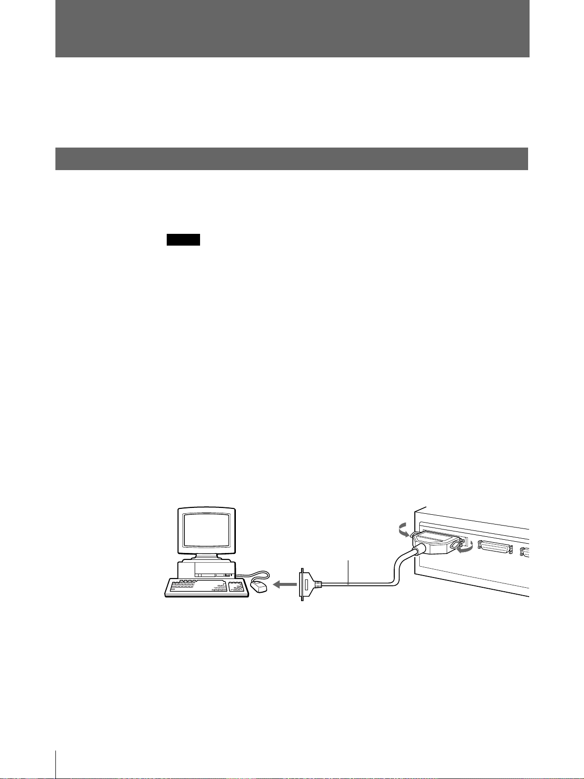
This device requires shielded interface cables to comply
with FCC emission limits.
R1.5m

3
Table of Contents
GB
English
Table of Contents
Introduction About this Manual .............................................................4
System Overview ..............................................................5
System Configuration....................................................... 5
Location and Function of Parts and Controls ................6
Front ................................................................................. 6
Rear .................................................................................. 7
Preparation Supplied Accessories.......................................................8
Assembly.......................................................................... 9
Connections ....................................................................10
Connecting the Computer .............................................. 10
Installing the Printer Driver Program............................. 11
Setting the DIP Switch ................................................... 11
Connecting the AC Power Cord..................................... 12
Setting the SCSI Device Type........................................ 13
Operation Before Printing ................................................................14
Loading an Ink Ribbon Cassette .................................... 14
Loading the Print Paper.................................................. 17
Printing.............................................................................20
Setting the Print Quantity...............................................23
Adjusting the Printouts ..................................................24
Adjusting the Gray Balance ...........................................26
Selecting the Gamma Curve ..........................................28
Setting the Margin Print Option .....................................29
Others Precautions......................................................................30
Safety.............................................................................. 30
Installation...................................................................... 30
On Transportation .......................................................... 31
Cleaning ......................................................................... 31
Ink Ribbon and Print Paper ............................................33
Specifications..................................................................34
Troubleshooting..............................................................35
Error Messages............................................................... 35
If the Paper Jams ............................................................ 37
Index.................................................................................39

4Introduction
Note
Introduction
About this Manual
Organization of this manual
This manual is divided into four chapters. This section explains the organization of
this manual.
Introduction
Describes the features and system configuration of the digital color printer. Also
provided is information on the location and function of parts.
Preparation
Explains the steps involved in setting up and connecting the printer prior to getting
started —checking the supplied accessories and assembly. Once all assembly and
all connections have been made, there should be no need to perform these
operations again during normal printing operations.
Operation
Describes loading of the ink ribbon cassette and print paper and actual printing
operation. Also provided is information on setting the print quantity and adjusting
the printouts and gray balance.
Others
Provides technical information on the printer, how to handle error messages
displayed in the printer window display, and how to deal with paper jams. Also the
index will assist you to locate the necessary section quickly. Refer to this chapter
when questions arise or problems occur.
Conventions used
Cross reference
Throughout this manual you will find the references to other sections of the manual
that contain related information.
Important note
Be sure to read the sections of the manual marked . They explain points that
you should be aware of to operate the printer correctly and prevent malfunctions.
Trademarks
Macintosh is the trademark of Apple Computer, Inc., USA.
MS-Windows and Windows95 are the trademarks of Microsoft Corporation, USA.

5
Introduction
System Overview
The Sony UP-D70XR digital color printer is designed to reproduce computer
images on A4-size and Letter-size print paper.
You can print out image data of Windows or Macintosh graphics application
software in high resolution (300dpi) and 256 shades of gray or in full color
(16,700,000 colors).
Combined with the UPA-D3 digital image processor (not supplied), you can use
the UP-D70XR as a printer conforming to the DICOM standard.
System Configuration
The following shows an example printer system configuration.
About the instruction manual of the printer driver
The instruction manual for the printer driver for the UP-D70A digital color printer
is stored on the CD-ROM supplied with the printer. Substitute this manual for the
printer driver manual for the UP-D70XR.
For detailed information, read the ReadMe file on the CD-ROM.
Computer
Controls the printer
operations.
Digital color printer

6Introduction
6ALARM indicator (35)
Lights in orange when the ink ribbon or print
paper is exhausted, the paper jams, or another
problem occurs.
7MENU button (13, 24, 26, 28, 29)
Press this button to display or close the
PRINT QTY, COLOR ADJUST, GRAY
ADJUST, GAMMA ADJUST or MARGIN
PRINT menu.
8Cursor control buttons (13, 23, 24, 26,
28, 29)
Use these buttons to increase or decrease a
value and level shown on the menu, or scroll
up and down through a menu.
9STOP button (21)
Press this button to stop printing part-way.
0PRINT button (20, 21, 23)
Press this button to print the image data stored
in the memory of the printer.
!¡ Paper cover (9)
Printouts are ejected here.
!™ Paper tray (9)
Load print paper here. Press the point marked
with PUSH to remove the paper tray.
Location and Function of Parts and Controls
For details, refer to the pages indicated in parentheses.
Front
1UPOWER switch
Press to turn the printer on or off.
2Fan cover (9, 32)
Provided to prevent the printer from dust.
3Ribbon door (15)
Pull the tab (marked with PULL) on the top
on the ribbon door to open it when loading an
ink ribbon cassette.
4PRINT QTY (quantity) button (23)
Press this button to display or close the print
quantity setting menu in the printer window
display.
5Printer window display
Displays the status messages. In menu
operation, the PRINT QTY (print quantity
setting) menu, COLOR ADJUST (printout
adjust) menu, GRAY ADJUST (gray balance
adjust) menu, GAMMA ADJUST (gamma
curve selection) menu or MARGIN PRINT
(margin print setting) menu is displayed.
Also, SCSI device type is dipslayed.
If an error occurs, a corresponding error
message is displayed.

7
Introduction
Rear
1PARALLE DATA IN (Amphenol
36-pin) (10)
Used to connect a Windows computer via the
parallel interface, using the parallel interface
cable. (not supplied)
2SCSI connectors (Half pitch 50-pin)
(11)
Used to connect a Windows or Macintosh
computer or another SCSI device, through the
SCSI cable. The other connector is loop-
through connector. If either of the two
connectors is not being used, set the
terminator of the DIP switch to ON.
(See “Setting the DIP Switch” on page 11.)
3Equipotential ground terminal 1
Used to connect to the equipotential plug to
bring the various parts of a system to the same
potential.
Refer to “Important safeguards/notices for use
in the medical environments” on page 2.
4DIP switch (11)
Used to set the SCSI ID number and the built-
in terminator to ON or OFF.
(See “Setting the DIP Switch” on page 11.)
5⁄AC IN connector (12)
Used to connect to a wall outlet, using the AC
power cord supplied.

8Preparation
Preparation
Supplied Accessories
This printer is packed together with the following accessories. Check that nothing
is missing from your package.
Notes
• Retain the original carton and packing materials in case you have to transport this
unit in the future.
• When transporting the pritner, lock the thermal head. (For detailed information
on how to lock, see page 31.)
Paper tray (1) Paper cover (1)
Ink ribbon holder (1)
Fan cover with a filter (1)
Fan cover Filter
Bottom cover (1)
Thermal Head Cleaning Kit (1)
AC power cord (1)
CD-ROM (1)
Operating Instructions (1)
Registration card
SOFTWARE LICENSE AGREEMENT

9
Preparation
Assembly
Mount the supplied ink ribbon holder, paper tray, paper cover, bottom cover and
fan cover.
Note
You cannot mount the ink ribbon holder when the thermal head is locked.
Before assembling, turn on the power of the printer. The thermal head is unlocked
and you can mount the ink ribbon holder.
When transporting the pritner, lock the thermal head. (For detailed information on
how to lock, see page 31.)
Paper cover
Paper tray (page 17)
Ink ribbon holder (page 14)
Bottom cover
Fan cover with a fiter
(page 32)

10 Preparation
Connections
This section introduces the connections of the printer.
For detailed information on how to connect the printer to the UPA-D3 digital
image processor, read the instruction manual supplied with the UPA-D3.
For further details, contact your Sony dealer.
Connecting the Computer
The printer connects to either of the computer Windows or Macintosh via the
parallel interface. The printer can also connect to the Macintosh computer via the
SCSI interface.
Notes
• Be sure to connect one printer to one computer. Do not connect two computers to
the printer.
• Do not connect the computer equipped with the SCSI interface and parallel
interface to both of the PARALLEL DATA IN connecter and SCSI connecter of
the printer at the same time.
• Before connecting the cable, make sure to turn off the power switches on your
computer and any peripheral equipment.
• Grasp the connector at the end of the cable, and firmly insert it into the socket.
• The total length of the SCSI cabling used with a single-host computer should be
less than 6 meters.
• The parallel data cable should be less than 3 meters long and should conform to
Centronics specifications for printer cables.
• Avoid sending parallel data to the printer while the printer is processing SCSI
commands, and vice versa.
• Cable connection requirements vary depending on computers and peripherals.
For the details of your installation, please refer to the manuals for your computer
and peripherals.
When connecting a printer via the parallel interface
Parallel data cable
(shielded type)

11
Preparation
Note
If the printer is connected at the physical end of the SCSI bus, set the built-in
terminator to ON (on this page).
Installing the Printer Driver Program
The printer driver program should be installed before starting operation.
The instruction manual for the printer driver for the UP-D70A digital color printer
is stored on the CD-ROM supplied with the printer. Substitute this manual for the
printer driver manual for the UP-D70XR.
For detailed information, read the ReadMe file on the CD-ROM.
Setting the DIP Switch
The DIP switches on the rear panel of the printer determine the on/off state of the
internal SCSI bus terminator and the SCSI device ID number.
As shipped from the factory, the DIP switches are set up as follows:
Terminator ON/OFF setting
If printer is located at the physical end of the SCSI bus, this switch should be set to
ON. Otherwise, if another device is at the end of the bus, this switch should be
OFF.
When connecting a printer via the SCSI interface
SCSI cable (shielded type)
(50 pin full - 50 pin half pitch)
Switch
TERMINATOR ON
The internal terminator is ON.a) OFF
The internal terminator is OFF.
ON 4 2 1
OFF 0 0 0
TERMINATOR
SCSI ID
(Factory setting)
a) Factory setting

12 Preparation
SCSI ID Setting
The SCSI ID selection must be different from any other device on the bus. If two
SCSI devices have the same ID, a malfunction will occur.
a) The SCSI ID has been set to 1 at the factory.
Connecting the AC Power Cord
Connect the supplied AC power cord to the AC IN connector on the rear of the
printer and then connect the cord to the wall outlet.
SCSI ID
0
1a)
2
3
4
5
6
7
SCSI ID Switch
4
0
0
0
0
4
4
4
4
2
0
0
2
2
0
0
2
2
1
0
1
0
1
0
1
0
1
To AC IN AC power cord
(supplied)
To wall outlet
Note
Operate the printer only on 220 to 240 V AC, 50/60 Hz.
Connections (Continued)

13
Preparation
Setting the SCSI Device Type
You need to set the SCSI Device Type, if an error for IOS. VXD occurs when the
printer is connected to the computer with Windows 95.
Or, obtain the updated IOS. VXD device driver and install the device driver in your
computer.
1While pressing the MENU button, turn on the power or the printer.
2Check that the SCSI Device Type is set to the system used in the printer
window display.
When your compuer is Windows 95, SCSI DEVICE TYPE should be set to 3.
2
<
3
>
SCS I Dev i ce Type
3If the setting is incorrect, set to the SCSI DEVICE TYPE to 3 using the ıor ∫
button.
4Turn off the printer.
The SCSI DEVICE TYPE is set to 3.

14 Operation
Operation
Before Printing
This section describes the operations that must be performed prior to starting
printing. This explanation assumes that the printer has already been installed and
that all connections have been made.
• Loading an ink ribbon cassette (on this page)
• Loading the print paper (page 17)
Once these operations have been completed, there should be no need to perform
them again during routine printing.
Notes
• When replacing the ink ribbon or paper, do not turn off the power. Turning off
the power will cause the image stored in the memory to be lost.
• After replacing the ink ribbon or paper, perform the gray balance adjustment.
(See “Adjusting the Gray Balance” on page 26.)
• Use the ink ribbon suitable for the type of print material. Before attempting to
load an ink ribbon, make sure that the combination of the ribbon and paper is
compatible. (“Ink Ribbon and Print Paper” on page 30.) If the printer detects an
incompatible combination, an error message appears in the printer window
display and operation is disabled.
•Use only ink ribbon and print paper designed for use with this printer.
Failing to do so is likely to result in unsatisfactory printing or malfunctions.
(“Ink Ribbon and Print Paper” on page 33.)
Loading an Ink Ribbon Cassette
Load the ink ribbon to the supplied ink ribbon holder, and load the ink ribbon
cassette (referring to the ink ribbon holder loaded with the ink ribbon) to the
printer’s ribbon compartment.
Notes
• When you use the printer at the first time, the thermal head was locked at the
factory. Turn on the printer first to unlock the thermal head, then start to load an
ink ribbon cassette. (See page 31.)
• Once an ink ribbon has been completely used, replace it. Ink ribbons are not
reusable.
• Do not rewind the ink ribbon for reuse.
• Do not touch the ink ribbon or place it in a dusty location. Finger prints or dust
on ink ribbon will result in imperfect printing.
• When transporting the printer, remove the ink ribbon cassette and lock the
thermal head. (For detailed information on how to lock the thermal head, see
page 31.)
•When using UPT-730BL blue thermal film:
It is not necessary to load the ink ribbon in the ink ribbon holder.
Detach the ink ribbon from the ink ribbon holder in step 3, then insert the
ink ribbon holder without the ink ribbon firmly until it stops in step 6.

15
Operation
1Open the ribbon door by pulling the tab on the ribbon door and marked with
PULL.
2Remove the ink ribbon cassette by pressing the EJECT button.
The ink ribbon cassette pops out.
Note
Never put your hand into the ink ribbon compartment. The thermal head
becomes very hot. You may burn yourself if you touch it.
3Detach the used ink ribbon from the ink ribbon holder.
4Load the ink ribbon to ink ribbon holder.
1Remove the spool with the
ink ribbon, while pressing in
the arrow direction.
2Remove the other spool.
Ink ribbon holder
(supplied)
1Load the spool holding the ink ribbon into the right-hand
part of the holder, while pressing in the arrow direction.
2Fit the other spool into the left-
hand part of the holder.
Bar code
(Continued)

16 Operation
5Remove any slack from the ink ribbon.
If the ribbon is left slack, it may be crumpled and damaged when inserted.
6Insert the ink ribbon cassette firmly until it stops.
7Close the ribbon door.
If your ink ribbon should tear
Repair the tear with transparent tape. There should be no problem with using the
remaining portion of the ribbon.
Notes When storing ink ribbons
• Avoid placing the ink ribbon in a location subject to:
– high temperatures
– high humidity
– excessive dust
– direct sunlight
• Store partially used ink ribbon in its original package.
SONY mark faces forwards.
Remove any slack.
Transparent
tape
Before Printing (Continued)
“Start” position marker
Wind the spool until the “Start” position
marker faces upward.

17
Operation
Loading the Print Paper
Load the print paper by the following procedure. Be careful not to touch the
printing surface of the paper.
Notes
• When loading the print paper, do not turn off the power. If you turn off the
power, the image data stored in the memory will be lost.
• When using UPT-730BL blue thermal film, the method for placing the blue
thermal file in the paper tray is different from those for other printing packs.
Read the instructions described in “To load the blue thermal file” on page 19
instead of the instructions in step 2.
1Push PUSH on the paper tray.
The paper tray is ejected.
2Open the tray cover and place the print paper in the paper tray.
Notes
The number of the print paper is the same as the number of the print paper that
one roll of the ink ribbon can afford. Usually the ink ribbon and paper have run
out at the same time. However, if you add only the print paper, pay attentions
to the following.
• The paper tray holds up to the total number of sheets contained in a package
sheets of paper. If you exceed this limit, paper jams may occur.
• If you load the paper that is not compatible with the ink ribbon used, the gray
balance may be changed.
• Load the paper so that it lays flat in the paper tray. If the paper is curled, it
will overflow the paper tray and the printing position may shift. If this
happens, load fewer sheets in the paper tray.
Remove the printing surface
protection sheet, if any.
Paper tray
Print surface
protection sheet
Place the print paper in the paper tray
with the printing surface (shiny side
with no legends) and its protection
sheet facing down.
Reverse side with printed logos
Riffle the paper.
When placing the
A4+ print paper,
pull up the tab and
slide the spacer
outward.
(Continued)

18 Operation
3Close the tray cover and slide the paper tray into the printer until it clicks into
place.
Notes on storing print paper
• Avoid storing the print paper in a location subject to:
– high temperatures
– high humidity
– excessive dust
– direct sunlight
• Use the original package for storing unused paper.
When using UPT-730BL blue thermal film
Notes
• Use the UPT-730BL blue thermal film specially made for the Sony UP-D70XR
series. If another type of thermal file is used, the quality of the printout cannot
be guaranteed. Use of another type of thermal film may also cause malfunction
of the printer.
• Sweat or dirt from hands on the film surface can cause a deterioration in the
quality of the printout.
• When using the blue thermal file, it is not necessary to load the ink ribbon
in the ink ribbon holder. Insert the ink ribbon holder without the ink
ribbon in the ribbon compartment.
Before Printing (Continued)

19
Operation
To load the blue thermal film
To load the blue thermal file, perform the following operation in step 2 in “Loading
the Print Paper” on page 17 instead of the operation instructed in step 2.
Place the thermal film sheets in the paper tray with the printing surface and its
protection sheet facing down. When properly placed, the squared-off corner of the
film sheets meets the caution labels attached to the side and bottom of the paper
tray.
Note
If you place the thermal film sheets in the paper tray with its printing surface facing
up, the error message “REMOVE PAPER AND PRESS [∫]” appears when
printing.
In such a case, remove the film sheet which was not ejected from the printer.
Be sure to place the thermal film sheets properly, then clean the thermal head using
the thermal head cleaning kit supplied with the printer.
For detailed information on how to clean, refer to the Operating Instructions
supplied with the thermal cleaning kit.
For detailed information on the error message, see the error message on page 36.
Notes on storing the blue thermal film
• Do not leave film or printed film in direct sunlight or bright room light. Store in a
dark area at low temperature (30 °C (80 °F) or lower) and low humidity.
We recommend storing the printed film in a polypropylene pouch in a cabinet.
• Do not allow any volatile organic solvent such as alcohol to come in contact with
the film.
Adhesion to cellophane tape or PVC will cause fading of the printout. Be careful
when storing film.
• Do not stack printed film on or under a freshly developed diazo copy sheet as this
could cause the film to turn black.
Thermal film (Place the film sheets in the paper
tray with its printing surface facing down.)
Squared-off corner
Protection sheet
Label attached on the bottom of
the paper tray.
Paper tray

20 Operation
Printing
Before printing
• Ensure that the printer is properly connected to the computer (page 10).
• Ensure that the combination of the ink ribbon and print paper is correct (pages 14
and 17).
• Ensure that the ink ribbon cassette and print paper are properly loaded (page 33).
1Turn on the power of the printer and computer.
When the printer is in standby status, the following message appears in the
printer window display.
A4 QTY 1
READY
Notes
•When the printer is connected to the computer through the SCSI bus, turn on
the power of the printer before turning on the computer.
•Never turn the printer on or off while the power of the computer is on.
2Send the image data from the computer to the printer, then enter the print
command or press the PRINT button of the printer.
1While the printer is receiving the image data from the computer, the
following message appears:
The data is written in the memory of the printer.
RGB
[
>>>
]
IMAGE TRANSFER
Printer window display
Paper outlet
1
2
STOP button
Number of copies to be printed
The size of the paper being loaded
Indicates the data is being transmitted.
(Continued)
Other manuals for UP-D70XR
1
Table of contents
Languages:
Other Sony Printer manuals

Sony
Sony LPR-1000MD User manual

Sony
Sony CVP-M3 User manual

Sony
Sony FilmStation UP-DF750 User manual

Sony
Sony SnapLab UP-CR15L Instruction manual

Sony
Sony UP-D890 User manual

Sony
Sony UP-DR80MD User manual

Sony
Sony UP55MD User manual

Sony
Sony UP-20 Manual

Sony
Sony UP-2100 User manual

Sony
Sony AC-T11 User manual