Sony UP-D55 User manual

2-059-514-13 (1)
Digital Color Printer
© 2004 Sony Corporation
UP-D55
Instructions for Use

2
Owner's Record
The model and serial numbers are located at the rear.
Record these numbers in the space provided below.
Refer to these numbers whenever you call upon your
Sony dealer regarding this product.
Model No. ____________________
Serial No. ____________________
To reduce the risk of fire or electric shock, do
not expose this apparatus to rain or moisture.
To avoid electrical shock, do not open the
cabinet. Refer servicing to qualified personnel
only.
No modification of this equipment is allowed.
THIS APPARATUS MUST BE EARTHED.
To disconnect the main power, unplug the
power plug.
When installing the unit, incorporate a readily
accessible disconnect device in the fixed
wiring, or connect the power plug to an easily
accessible socket-outlet near the unit.
Do not position the ME equipment where it is
difficult to unplug the power plug.
If a fault should occur during operation of the
unit, operate the disconnect device to switch
the power supply off, or unplug the power plug.
For the customers in the U.S.A.
This equipment has been tested and found to comply
with the limits for a Class A digital device, pursuant to
Part 15 of the FCC Rules. These limits are designed to
provide reasonable protection again harmful
interference when the equipment is operated in a
commercial environment. This equipment generates,
uses, and can radiate radio frequency energy and, if not
installed and used in accordance with the instruction
manual, may cause harmful interference to radio
communications. Operation of this equipment in a
residential area is likely to cause harmful interference in
which case the user will be required to correct the
interference at his own expense.
You are cautioned that any changes or modifications not
expressly approved in this manual could void your
authority to operate this equipment.
All interface cables used to connect peripherals must be
shielded in order to comply with the limits for a digital
device pursuant to Subpart B of Part 15 of FCC Rules.
For the customers in Canada
This unit has been certified according to Standard CAN/
CSA-C22.2 No.60601-1.
For the customers in the U.S.A and
Canada
When you use this product connected to 240 V single
phase, be sure to connect this product to a center tapped
circuit.
Important safeguards/notices for use in
the medical environments
1. All the equipments connected to this unit shall be
certified according to Standard IEC60601-1,
IEC60950-1, IEC60065 or other IEC/ISO Standards
applicable to the equipments.
2. Furthermore all configurations shall comply with the
system standard IEC60601-1-1. Everybody who
connects additional equipment to the signal input
part or signal output part configures a medical
system, and is therefore, responsible that the system
complies with the requirements of the system
standard IEC60601-1-1. If in doubt, consult the
qualified service personnel.
3. The leakage current could increase when connected
to other equipment.
4. For this particular equipment, all accessory
equipment connected as noted above, must be
connected to mains via an additional isolation
transformer conforming with the construction
requirements of IEC60601-1 and providing at least
Basic Insulation.
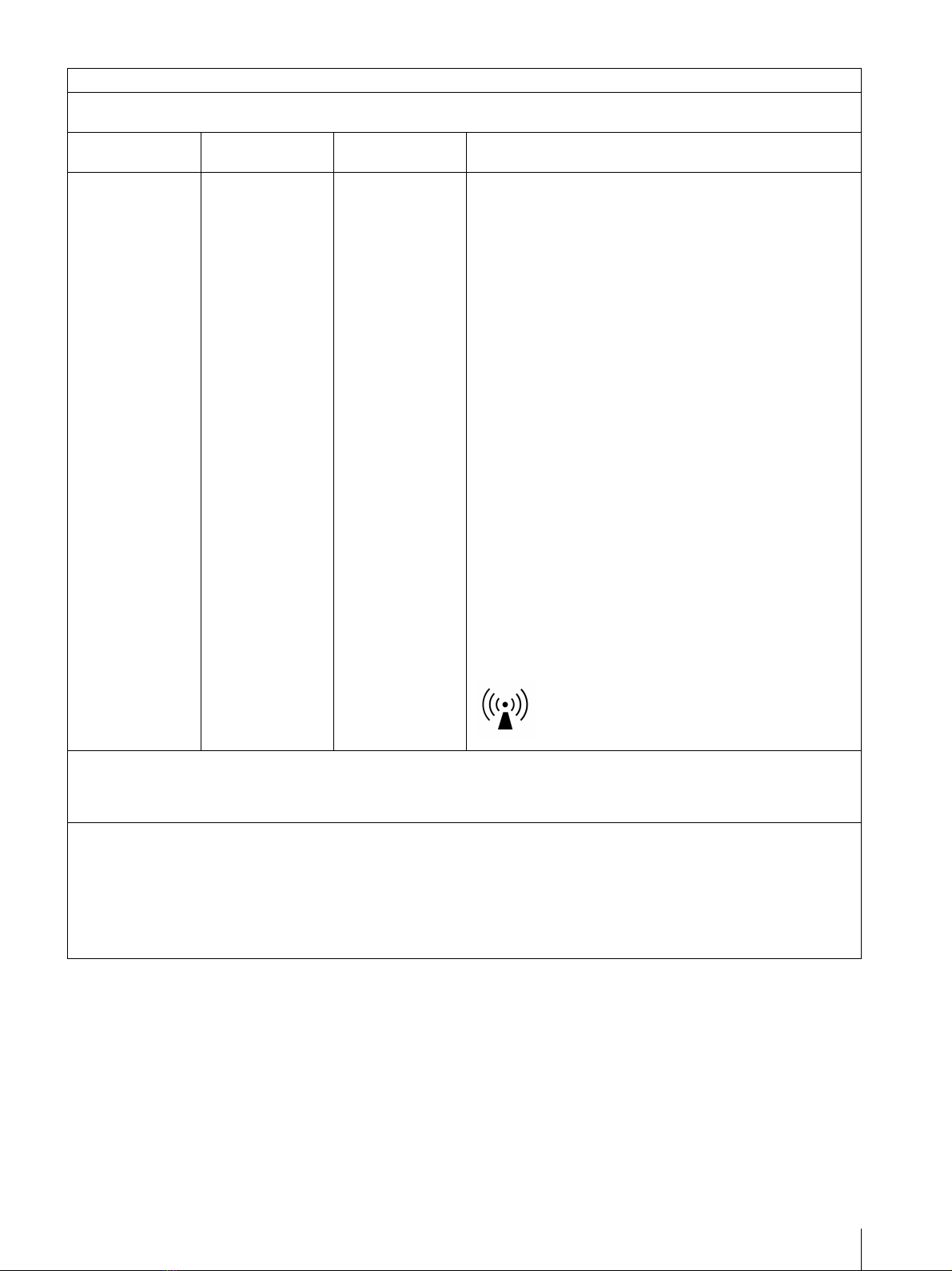
5. This equipment generates, uses, and can radiate radio
frequency energy. If it is not installed and used in
accordance with the instruction manual, it may cause
interference to other equipment. If this unit causes
WARNING
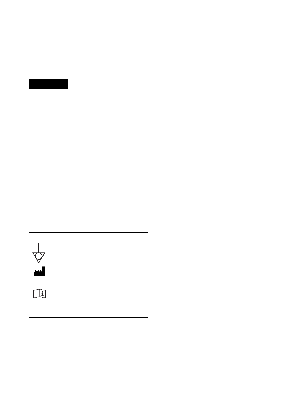
Symbols on the products
This symbol indicates the equipotential
terminal which brings the various parts of a
system to the same potential.
This symbol indicates the manufacturer, and
appears next to the manufacturer’s name and
address.
Refer to the operating instructions
Follow the directions in the operating
instructions for parts of the unit on which
this mark appears.

3
interference (which can be determined by
unplugging the power cord from the unit), try these
measures: Relocate the unit with respect to the
susceptible equipment. Plug this unit and the
susceptible equipment into different branch circuit.
Consult your dealer. (According to standard EN60601-
1-2 and CISPR11, Class B, Group 1)
Important EMC notices for use in the medical environments
• The UP-D55 needs special precautions regarding EMC
and needs to be installed and put into service according
to the EMC information provided in this instructions for
use.
• The portable and mobile RF communications equipment
such as cellular phones can affect the UP-D55.
Warning
The use of accessories and cables other than those
specified, with the exception of replacement parts sold by
Sony Corporation, may result in increased emissions or
decreased immunity of the UP-D55.
Warning
If the UP-D55 should be used adjacent to or stacked with
other equipment, it should be observed to verify normal
operation in the configuration in which it will be used.
Guidance and manufacturer’s declaration-electromagnetic emissions
The UP-D55 is intended for use in the electromagnetic environment specified below.
The customer or the user of the UP-D55 should assure that it is used in such an environment.
Emission test Compliance Electromagnetic environment-guidance
RF emissions
CISPR 11
Group 1
The UP-D55 uses RF energy only for its internal function.
Therefore, its RF emissions are very low and are not likely
to cause any interference in nearby electronic equipment.
RF emissions
CISPR 11
Class B
The UP-D55 is suitable for use in all establishments,
including domestic establishments and those directly
connected to the public low-voltage power supply network
that supplies buildings used for domestic purposes.
Harmonic emissions
IEC 61000-3-2
Class A
Voltage fluctuations/
flicker emissions
IEC 61000-3-3
Complies

4
Guidance and manufacturer’s declaration - electromagnetic immunity
The UP-D55 is intended for use in the electromagnetic environment specified below. The customer or the user of the UP-
D55 should assure that it is used in such as environment.
Immunity test IEC 60601 test
level Compliance level Electromagnetic environment-guidance
Electrostatic
discharge (ESD)
IEC 61000-4-2
±6 kV contact
±8 kV air
±6 kV contact
±8 kV air
Floors should be wood, concrete or ceramic tile. If floors are
covered with synthetic material, the relative humidity should
be at least 30%.
Electrical fast
transient/burst
IEC 61000-4-4
±2 kV for power
supply lines
±1 kV for input/
output lines
±2 kV for power
supply lines
±1 kV for input/
output lines
Mains power quality should be that of a typical commercial or
hospital environment.
Surge
IEC 61000-4-5
±1 kV differential
mode
±2 kV common
mode
±1 kV differential
mode
±2 kV common
mode
Mains power quality should be that of a typical commercial or
hospital environment.
Voltage dips, short
interruptions and
voltage variations
on power supply
input lines
IEC 61000-4-11
< 5% UT
(> 95% dip in UT)
for 0.5 cycle
40% UT
(60% dip in UT)
for 5 cycles
70% UT
(30% dip in UT)
for 25 cycles
< 5% UT
(> 95% dip in UT)
for 5 sec
< 5% UT
(> 95% dip in UT)
for 0.5 cycle
40% UT
(60% dip in UT)
for 5 cycles
70% UT
(30% dip in UT)
for 25 cycles
< 5% UT
(> 95% dip in UT)
for 5 sec
Mains power quality should be that of a typical commercial or
hospital environment. If the user of the UP-D55 requires
continued operation during power mains interruptions, it is
recommended that the UP-D55 be powered from an
uninterruptible power supply or a battery.
Power frequency
(50/60 Hz)
magnetic field
IEC 61000-4-8
3 A/m 3 A/m Power frequency magnetic fields should be at least
characteristic of a typical location in a typical commercial or
hospital environment.
NOTE: UTis the a.c. mains voltage prior to application of the test level.

5
Guidance and manufacturer’s declaration - electromagnetic immunity
The UP-D55 is intended for use in the electromagnetic environment specified below. The customer or the user of the UP-
D55 should assure that it is used in such as environment.
Immunity test IEC 60601 test
level Compliance level Electromagnetic environment-guidance
Conducted RF
IEC 61000-4-6
Radiated RF
IEC 61000-4-3
3 Vrms
150 kHz to 80 MHz
3 V/m
80 MHz to 2.5 GHz
3 Vrms
3 V/m
Portable and mobile RF communications equipment should
be used no closer to any part of the UP-D55, including
cables, than the recommended separation distance
calculated from the equation appliance to the frequency of
the transmitter.
Recommended separation distance
d= 1.2 √P
d= 1.2 √P80 MHz to 800 MHz
d= 2.3 √P800 MHz to 2.5 GHz
Where Pis the maximum output power rating of the
transmitter in watts (W) according to the transmitter
manufacturer and dis the recommended separation distance
in meters (m).
Field strengths from fixed RF transmitters, as determined by
an electromagnetic site survey, ashould be less than the
compliance level in each frequency range. b
Interference may occur in the vicinity of equipment marked
with following symbol:
NOTE 1: At 80 MHz and 800 MHz, the higher frequency range applies.
NOTE 2: These guidelines may not apply in all situations. Electromagnetic propagation is affected by absorption and
reflection from structures, objects and people.
a Field strengths from fixed transmitters, such as base stations for radio (cellular/cordless) telephones and land mobile
radios, amateur radio, AM and FM radio broadcast and TV broadcast cannot be predicted theoretically with accuracy. To
assess the electromagnetic environment due to fixed RF transmitters, an electromagnetic site survey should be
considered. If the measured field strength in the location in which the UP-D55 is used exceeds the applicable RF
compliance level above, the UP-D55 should be observed to verify normal operation. If abnormal performance is observed,
additional measures may be necessary, such as reorienting or relocating the UP-D55.
b Over the frequency range 150 kHz to 80 MHz, field strengths should be less than 3 V/m.

6
Caution
When you dispose of the unit or accessories, you must
obey the law in the relative area or country and the
regulation in the relative hospital.
Warning on power connection
Use a proper power cord for your local power supply.
1. Use the approved Power Cord (3-core mains lead) /
Appliance Connector / Plug with earthing-contacts
that conforms to the safety regulations of each
country if applicable.
2. Use the Power Cord (3-core mains lead) / Appliance
Connector / Plug conforming to the proper ratings
(Voltage, Ampere).
If you have questions on the use of the above Power
Cord / Appliance Connector / Plug, please consult a
qualified service personnel.
Warning on power connection for
medical use
Please use the following power supply cord.
With connectors (plug or female) and cord types other
than those indicated in this table, use the power supply
cord that is approved for use in your area.
*Note: Grounding reliability can only be achieved when the equip-
ment is connected to an equivalent receptacle marked ‘Hospital Only’
or ‘Hospital Grade’.
For the customers in Europe
This product has been manufactured by or on behalf of
Sony Corporation, 1-7-1 Konan Minato-ku Tokyo, 108-
0075 Japan. Inquiries related to product compliance
based on European Union legislation shall be addressed
to the authorized representative, Sony Deutschland
GmbH, Hedelfinger Strasse 61, 70327 Stuttgart,
Germany.
For any service or guarantee matters, please refer to the
addresses provided in the separate service or guarantee
documents.
Recommended separation distances between portable and mobile RF communications equipment and the UP-D55
The UP-D55 is intended for use in an electromagnetic environment in which radiated RF disturbances are controlled. The
customer or the user of the UP-D55 can help prevent electromagnetic interference by maintaining a minimum distance
between portable and mobile RF communications equipment (Transmitters) and the UP-D55 as recommended below,
according to the maximum output power of the communications equipment.
Rated maximum output power of transmitter
W
Separation distance according to frequency of transmitter
m
150 kHz to 80 MHz
d= 1.2 √P
80 MHz to 800 MHz
d= 1.2 √P
800 MHz to 2.5 GHz
d= 2.3 √P
0.01 0.12 0.12 0.23
0.1 0.38 0.38 0.73
1 1.2 1.2 2.3
10 3.8 3.8 7.3
100 12 12 23
For transmitters rated a maximum output power not listed above, the recommended separation distance din meters (m) can
be estimated using the equation applicable to the frequency of the transmitter, where Pis the maximum output power rating
of the transmitter in watts (W) according to the transmitter manufacturer.
NOTE 1: At 80 MHz and 800 MHz, the separation distance for the higher frequency range applies.
NOTE 2: These guidelines may not apply in all situations. Electromagnetic propagation is affected by absorption and
reflection from structures, objects and people.
United States and Canada
Plug Type HOSPITAL GRADE*
Cord Type Min.Type SJT
Min.18 AWG
Minimum Rating for Plug
and Appliance Couplers
10 A/125 V
Safety Approval UL Listed and CSA

7
Table of Contents
Getting Started
System Overview ................................................... 8
System Configuration ......................................... 8
Location and Function of Parts and Controls .... 8
Front Panel ......................................................... 8
Rear Panel .......................................................... 9
Supplied Accessories ............................................. 9
Connections .......................................................... 10
USB Port Connection ....................................... 10
Installing the Printer Driver ............................... 10
Operation
Before Printing ..................................................... 12
Loading an Ink Ribbon Cartridge ..................... 12
Inserting the Paper Tray ................................... 15
Printing ................................................................. 16
Miscellaneous
Precaution ............................................................ 18
Safety ................................................................ 18
Installation ........................................................ 18
Before Transporting the Printer ........................ 18
Cleaning ........................................................... 18
Ink Ribbon and Paper ......................................... 19
Specifications ........................................................ 19
Troubleshooting ................................................... 20
Indicators on the Ribbon Door ........................... 21
If the Paper Jams ................................................. 22
Index ..................................................................... 24

Getting Started
System Overview / Location and Function of Parts and Controls
8
Getting Started
System Overview
The UP-D55 digital color printer is designed to
reproduce computer images on A-5 size paper.
You can print out computer image data in full color (with
256 shades per color, a total of more than 16,700,000
colors in all) in high resolution print mode
(approximately 379 dpi).
System Configuration
The following shows an example of a printer system
configuration.
Location and Function
of Parts and Controls
For details, refer to the pages given in parentheses.
Front Panel
APOWER indicator
Lights when the POWER switch of the printer is set
to ON.
BPRINT indicator (21)
Lights while the printer is printing.
CALARM indicator (21)
Lights in orange in case of paper jamming or
occurrence of any other problem.
DRIBBON indicator (21)
Lights when a problem for ink ribbon occurs.
EPAPER indicator (21)
Lights when a problem for paper occurs.
The printer allows you to check the printer
operating condition according to the lighting
conditions of the PRINT indicator, ALARM
indicator, PAPER indicator and RIBBON indicator.
For details, see “Indicators on the Ribbon Door” on
page 21.
FSTOP button (17)
Press this button to stop printing multiple copies of
identical printouts. The printer finishes printing the
current copy and ejects it. Then the printer turns to
stand by mode.
Computer
Controls the printer operation.
Digital color printer

Getting Started
Supplied Accessories 9
GPaper output slot
Printed pages are ejected here.
HPaper tray (16)
Load paper into this tray.
I!POWER switch (16)
Press this switch to turn the printer on or off.
Rear Panel
A-AC IN connector
Use a proper power cord for your local power
supply (not supplied).
Refer to “Warning on power connection” on page 6
and “Warning on power connection for medical
use” on page 6.
BEquipotential ground terminal connector
Used to connect to the equipotential plug to bring
the various parts of a system to the same potential.
Refer to “Important safeguards/notices for use in
the medical environments” on page 2.
CUSB cable clamp
Used to secure the USB cable.
D(USB) connector (10)
Connects to a computer or another USB peripheral
device with a USB cable (supplied).
ESwitch
Not used at present.
Supplied Accessories
The printer is packed together with the following
accessories. Check that nothing is missing from your
package.
Notes
• Retain the original carton and packing materials in
case you have to transport the unit in the future.
• Remove the ink ribbon cartridge and paper tray when
transporting the printer.
Paper Tray (1)
Ink ribbon holder (1)
USB cable 1-824-211-41 (Sony) (1)
Software Licence Agreement (1)
CD-ROM (including the printer drivers and
PDF files of multi-lingual Instructions For
Use) (1)
Before Using this Printer (1)
Service Contact List (1)

Getting Started
Connections / Installing the Printer Driver
10
Connections
After connecting the USB connecting cable (supplied)
to the printer and the computer, connect the power cord.
For details about the printer connection, refer to the
manuals for the computer or other peripheral devices.
Notes
• Before connecting the printer to the computer, turn off
the printer, computer, monitor, and all peripheral
devices connected to the computer.
• Before connecting the printer to the computer,
disconnect the power cord from the printer. Connect
the power cord to the printer only after connecting the
printer and the computer.
• Follow the connection procedures described in the
computer manual.
• Make sure that the interface cable is connected
securely at both ends.
• The printer drive software provided with the printer is
not suitable for using the printer connected to a
network.
• Operation of the printer is not guaranteed for
connection to a USB hub.
USB Port Connection
Installing the Printer
Driver
Install the printer driver provided with the printer. For
detailed instructions on how to install the printer driver,
refer to the Readme.txt file on the printer driver installer
disc.
About USB (Universal Serial Bus) Specification
Revision 2.0
• The UP-D55 complies with the USB 2.0 specification.
• USB 2.0 is a newer standard than USB 1.1, but
provides backward compatibility.
• USB 2.0 supports Hi-speed USB, in addition to the
existing Full (Low) speed.
• The UP-D55 can be connected as Full-speed in a USB
1.1 environment. However, to use the UP-D55 with
Hi-speed USB functions in a USB 1.1 environment,
the following requirements must be met.
–Computer
A computer which supports Hi-speed USB
(conforming to the USB 2.0 specification) a)
–OS
Windows 2000/Windows XP
– USB 2.0 device driver
USB 2.0 device driver produced by Microsoft
Corporation. (Operation using USB 2.0 drivers
other than ones produced by Microsoft Corporation
is not guaranteed.)
– USB 2.0 cable
Use the 2-m cable supplied with the UP-D55.
to (USB) connector
USB cable
(supplied)
UP-D55
UP-D55

Getting Started
Installing the Printer Driver 11
a) Operations of all of devices which conform to USB
2.0, or all USB 2.0 extension boards/extension
cards cannot be guaranteed.
Note
When the UP-D55 is connected to the computer with the
power turned on, do not turn your computer to standby
mode (suspend status) or in pause mode. Doing so may
cause a malfunction of the operation.

Operation
Before Printing
12
Operation
Before Printing
This section describes the operations below that must be
made before printing, but after making the necessary
connections. (See “Connections” on page 10.)
• Loading an ink ribbon cartridge (See below.)
• Inserting the paper tray (See page 15.)
Once the above operations have been completed, there
should be no need to repeat them during routine printing.
Perform them only as necessary.
Notes
• You can replace the ink ribbon or load paper
regardless of whether the power is on or off.
• When either an ink ribbon or paper has been
exhausted, replace both the ink ribbon and paper at
the same time.
• Use only ink ribbon and paper designed for use with
this printer. Failing to do so is likely to result in
malfunctions. (See“Ink Ribbon and Paper” on page
19.)
Loading an Ink Ribbon Cartridge
To make printouts, an ink ribbon cartridge (an ink ribbon
holder which has been loaded with an ink ribbon) and
paper must be loaded. This section describes how to set
the ink ribbon into the supplied ink ribbon holder and to
load the ink ribbon cartridge in the printer.
When you use the printer for the first time, start the
operation to load the ink ribbon cartridge from step 4.
Notes
• When you use the printer for the first time, the
thermal head may be out of position. Before
attempting to load the ink ribbon cartridge, turn
on the power under the condition where the ribbon
door is closed so that the thermal head is placed at
the correct position.
• If a blank sheet of paper is ejected, and the RIBBON
indicator lights, the ink ribbon has been exhausted.
Replace the paper together with the ink ribbon. Do not
reuse the ejected blank paper.
• Once an ink ribbon has been completely used up,
replace it. An ink ribbon is not reusable.
• Do not rewind the ink ribbon for reuse.
• Do not touch the ink ribbon or place it in a dusty
location. Finger prints or dust on the ink ribbon will
result in imperfect printing or malfunction of the head.
1
Open the ribbon door by pulling the ribbon door
toward you.
2
Remove the ink ribbon cartridge.
If you can not remove the ink ribbon
cartridge
The thermal head may be out of position.
In such a case, close the ribbon door, and turn the
power off, then back on again. After a while, start
the operation from step 1 again.

Operation
Before Printing 13
3
Detach the spent ink ribbon from the ink ribbon
holder.
4
Load the new ink ribbon into the ink ribbon holder.
1Holding the ink ribbon firmly, remove the gear
cover.
2Place the ink ribbon with the white gear as
illustrated.
3Place the ink ribbon with the gray gear in the
same way as explained in step 2.
4Eliminate any slack in the ribbon by turning the
gears.
Pushing the ink ribbon spool that takes up the ink
ribbon in the direction of the arrow, remove the
spool from the side with the gray gear.
Pushing the ink ribbon spool that sends the ink
ribbon in the direction of the arrow, remove the
spool from the side with the white gear.
Gear cover
To avoid dropping the ink ribbon, make
sure that you hold it firmly.
2Press the other side of the ink ribbon
until you hear it click into place.
1Press the white gear of
the ink ribbon.
Match the color of the
gear of the ink ribbon
spool and the color of the
ink ribbon holder.
1Press the gray gear of
the ink ribbon.
2Press the other side of the ink ribbon
until you hear it click into place.

Operation
Before Printing
14
Note
If the ribbon is left slack, it may be damaged
when the ink ribbon cartridge is inserted into
the printer.
5
Insert the ink ribbon cartridge until it stops.
If the ink ribbon cartridge cannot be
inserted
In such a case, close the ribbon door, and turn the
power off, then back on again. Insert the ink ribbon
cartridge again.
6
Close the ribbon door.
Notes
When handling the ink ribbon:
• Do not rewind the ink ribbon for reuse.
• When handling the ink ribbon, be careful not to touch
the surface of the ink ribbon. Dust or finger prints are
likely to cause unsatisfactory printing or malfunction
of the head.
When storing ink ribbon:
• Avoid placing the ink ribbon in a location subject to:
– high temperatures
– high humidity
– excessive dust
– direct sunlight
• Store a partially used ink ribbon in its original
packaging.
If your ink ribbon should tear
Repair the tear with transparent tape. There should be no
problem with using the remaining portion of the ribbon.
Turn the gears in the direction of the
arrows until any slack is eliminated
and the magenta section of the ink
ribbon appears.
Transparent tape
Turn the gray gear of the spool that takes up the
ink ribbon in the direction of the arrow to remove
any slack until the transparent tape cannot be
seen.

Operation
Before Printing 15
Inserting the Paper Tray
To load paper in the paper tray and insert the paper tray
into the printer, follow the procedure below. Be careful
not to touch the printing surface of the paper.
When you use the printer for the first time, start the
operation to insert the paper tray from step 2.
Notes
• Use only the paper recommended. Failing to do so is
likely to result in malfunctions such as paper jams.
(See “Ink Ribbon and Paper” on page 19.)
• When a blank sheet of paper is ejected and the
RIBBON indicator lights, the ink ribbon has been
exhausted. Replace the paper together with the ink
ribbon. Do not use the ejected blank paper.
• Be careful when removing and inserting the paper
tray. If you are not careful, you may drop the printer.
1
Push the paper tray to remove it.
2
Place the paper in the paper tray so that the printing
surface faces up with the protection sheet on top.
Notes
• Do not add only the paper. When the paper supply
has been exhausted, replace both the ink ribbon
and paper at the same time. If you add paper
while printing, this may cause the paper jam.
• When handling the paper, do not touch the
printing surface. Dust or finger prints are likely to
cause unsatisfactory printing or malfunction of
the head. Grasp the paper by the printing surface
protection sheet.
• Load the paper so that it lays flat in the paper tray.
If the paper is curled, it will overflow from the
paper tray and paper may not be fed properly. Be
sure to riffle the paper along with the protection
sheets before placing the paper in the paper tray.
3
Remove the protection sheet placed on the top of
the paper.
Riffle the paper with
the protection sheet.
Place paper with
the arrow pointing
in the same
direction as in the
tray.

Operation
Printing
16
4
Slide the paper tray back into the printer until it
clicks into place.
Note
If you cannot insert the ink ribbon cartridge
completely, check whether any paper is left inside
the printer. If you find a left sheet, slowly pull it
straight out.
How to use the paper eject stopper
To keep ejected printouts on the paper tray, pull the
paper eject stopper on the paper tray out until it clicks.
Note
Do not leave more than 10 sheets of ejected printouts.
Doing so may cause a paper jam.
When storing the paper
• Avoid storing the paper in a location subject to:
– high temperatures
– high humidity
– excessive dust
– direct sunlight
• Use the original package for storing unused paper.
Printing
Before printing
• Ensure that the printer is properly connected to the
computer. (See page 10.)
• Ensure that the ink ribbon cartridge and paper tray are
properly loaded. (See pages 12 and 15.)
• Ensure that the printer driver has been installed. (See
page 10.)
1
Press the POWER switch to turn the printer on.
The POWER indicator lights.
PRINT, ALARM, RIBBON and PAPER indicators
light at the same time, then all of them go out.
Notes
• Turn the printer on first.
• Do not turn the computer off and on while it is
accessing a hard or floppy disk.
2
Turn on the power of the computer.
3
Execute the print job with software application.
While the printer is receiving the image data from
the computer, the PRINT indicator blinks.
While the printer is printing, the PRINT indicator
lights.
Notes
• Do not pull the paper out till the printer finishes
printing.
• Do not turn off the power during printing. If you do so,
paper may not be ejected and may jam in the printer.
• Do not open the ribbon door while the printer is
printing. If you open the ribbon door, the printer stops
printing. When you close the ribbon door, the sheet
Pull the paper eject stopper
on the paper tray out until it
clicks.
POWER indicator
PRINT indicator
ALARM indicator
RIBBON indicator
PAPER indicator
1

Operation
Printing 17
being printed when you opened the ribbon door is
ejected and the printer turns to the standby mode.
• You can make multiple copies of identical printouts.
However, the printer may stop printing due to warping
of the printed sheet and the ALARM indicator lights.
In such a case, remove the printouts accumulated on
the paper tray. The printer will start to print the
remaining copies automatically.
• Do not leave more than 10 sheets of ejected printouts
on the paper tray. Doing so may cause a paper jam.
If the printer does not print
The printer will fail to print when the ALARM, PAPER,
and/or RIBBON indicator light.
For details, see “Indicators on the Ribbon Door” on page
21.
If the paper or ink ribbon runs out during
printing
The printer stops the printing operation.
Load the paper into the paper tray and the ink ribbon.
Printing of remaining copies is automatically started.
To stop the printing multiple copies of identical
printouts
Press the STOP button. The printer finishes current
printing and ejects it. Then, it turns in standby mode.
When storing your printouts
• Avoid storing the printout in a location subject to high
temperatures, high humidity, excessive dust and direct
sunlight.
• Do not stick tape on a printout. Also, avoid leaving a
plastic eraser on a printout or placing a printout in
contact with materials which contain plasticizer
(under a desk mat, for example).

Miscellaneous
Precaution
18
Miscellaneous
Precaution
Safety
• Operate the printer using the power source specified in
“Specifications” on page 19.
• Be careful not to damage the AC power cord by
placing or dropping heavy objects on it; it is dangerous
to use the unit with a damaged AC power cord.
• If you do not intend to use the unit for a long time,
disconnect the AC power cord.
• Unplug the AC power cord by grasping the plug, not
the cable itself.
• Do not disassemble the unit.
• Do not remove the cover. There is a danger of electric
shock from the internal parts.
• Be careful not to spill water or other liquids on the
unit, or to allow combustible or metallic material to
enter the cabinet. If used with foreign matter in the
cabinet, the unit is liable to fail, or present a risk of fire
or electric shock.
• Ventilation holes are provided to prevent the unit from
overheating. Be careful not to obstruct them with other
units or by covering the unit with a cloth, etc.
• If the unit malfunctions or if a foreign body falls into
the cabinet, disconnect the AC power cord
immediately and consult your Sony service facility or
your Sony dealer.
Installation
• Avoid placing the unit in a location subject to:
– mechanical vibration
– high humidity
– excessive dust
– direct or excessive sunlight
– extremely high or low temperatures
• Do not use other electronic equipment near the unit.
The unit will not work properly in strong
electromagnetic fields.
• Do not place a heavy object such as a monitor on the
printer.
Condensation
• If the printer is subject to wide or sudden changes in
temperature, such as when it is moved from a cold
room to a warm room or when it is left in a room with
a heater that tends to produce large amounts of
moisture, condensation may form inside the printer. In
such cases the printer will probably not work properly,
and may even develop a fault if you persist in using it.
If condensation forms, turn off the power and leave the
printer to stand for at least one hour.
• If the printing pack is subjected to wide or sudden
changes in temperature, condensation may form on
the ink ribbon or paper. This will cause the printer to
malfunction. Also, if the printing pack is used in this
state, spots are likely to appear on the printout.
Therefore, avoid storing the printing pack in locations
subject to wide or sudden changes of temperature.
• To store a half-used printing pack, replace it in its
original packing and reseal the package. If possible,
keep the sealed printing pack in a cool, dark location.
To subsequently use the printing pack, place it, in its
sealed package, in a warm room for several hours.
Doing so prevents condensation from forming when
the printing pack is removed from its package.
Location
To prevent internal heat built-up, leave enough room
around the printer for air to circulate through the vents
on the left hand side and top of the cabinet.
Before Transporting the Printer
Before transporting the printer, remove ink ribbon
cartridge and paper tray and then put them back into
their original packing. Transporting the printer with the
supplied accessories still installed may cause
malfunctions.
Cleaning
Note
Be sure to turn off the power of the printer and
disconnect the AC power cord from the wall outlet
before cleaning.
Cleaning the cabinet
Clean the cabinet, panel and controls with a soft dry
cloth, or a soft cloth lightly moistened with a mild
detergent solution. Do not use any type of solvent, such
as alcohol or benzine, which may damage the finish.

Miscellaneous
Ink Ribbon and Paper / Specifications 19
Ink Ribbon and Paper
Both paper and an ink ribbon are necessary for printing.
Use the ink ribbon with the paper contained in the same
package.
UPC-55 Color Printing Pack
Contains color ink ribbon cartridge and paper.
Color ink ribbon for 100 sheets, 2 rolls
Paper, 1 package (100 sheets) ×2
Note
If the paper has been exhausted, replace the ink ribbon
together with the paper.
Specifications
Power requirements
100 to 120 V AC, 50/60 Hz
(for 100 to 120 V AC users)
220 to 240 V AC, 50/60 Hz
(for 220 to 240 V AC users)
Input Current 2.8 A max. at 25 °C
(for 100 to 120 V AC users)
1.2 A max. at 25 °C
(for 220 to 240 V AC users)
Operating temperature
5 °C to 35 °C (41 °F to 95 °F)
Operating humidity
20% to 80% (no condensation allowed)
Operating pressure
700 hPa to 1,060 hPa
Storage and transport temperature
–20 °C to 60 °C (–4 °F to 140 °F)
Storage and transport humidity
20% to 90% (no condensation allowed)
Storage and transport pressure
700 hPa to 1,060 hPa
Dimensions Approx. 280 × 125 × 398 mm (w/h/d)
(11 1/8 × 5 × 15 3/4 inches)
Mass Approx. 9 kg (19 lb 13 oz)
Printing system
Sublimation heat transfer printing
Printable pixels
When printing the full-image: 2528 ×
1920 dots
Total gradation 256 levels each for yellow, magenta,
and cyan
Printing time When the printer is set to high speed:
Approximately 20 seconds
Thermal head 14.93 dots/mm
(USB) connector
Universal Serial Bus (USB)
Specification Revision 2.0
Input connector
AC IN (for power input)
Supplied accessories
Paper tray (1)
USB cable 1-824-211-41 (Sony) (1)
Ink ribbon holder (1)
Software License Agreement (1)
Before Using this Printer (1)
CD-ROM (including the printer drivers
and PDF files of multi-lingual
Instructions For Use) (1)
Service Contact List (1)
Optional accessories
UPC-55 Color Printing Pack
Medical Specifications
Protection against electric shock:
Class I

Miscellaneous
Troubleshooting
20
Protection against harmful ingress of
water:
Ordinary
Degree of safety in the presence of a
flammable anesthetic mixture with
air or with oxygen or nitrous oxide:
Not suitable for use in the presence
of a flammable anesthetic mixture
with air or with oxygen or nitrous
oxide
Mode of operation:
Continuous
Design and specifications are subject to change without
notice.
Troubleshooting
The following troubleshooting checks will help you
correct the most common problems you may encounter
with your unit. Before proceeding with these trouble
checks, first check that the power cord is firmly
connected. Should the problem persist after you have
applied the remedy, unplug the unit and contact your
Sony dealer or local authorized Sony service facility.
Symptoms Possible causes and remedies
The printer does not
print, even if the
command is sent
from the computer.
• The POWER switch of the printer is
not set to ON.
tSet the POWER switch of the
printer to ON.
• Connections may not be correct.
tCheck connections and rectify, if
necessary. (See page 10.)
The printer does not
print.
The problem is indicated by the
indicators on the ribbon door.
tSee “Indicators on the Ribbon
Door” on page 21.
The printout color is
very pale.
The paper is not loaded correctly.
tCheck which side of the paper is the
printing side, then load the paper
again. (See page 15.)
The ink ribbon cannot
be set.
You may be trying to load an ink ribbon
that can not be used with this printer
has been loaded.
tLoad the appropriate ink ribbon.
(See page 19.)
The ink ribbon
cartridge cannot be
loaded.
• The thermal head has moved out of
position.
tClose the ribbon door, and turn
the power off, then back on
again. The thermal head moves
so that you can now install the
ink ribbon cartridge. (See
page 12.)
• The ink ribbon is not loaded
correctly.
tLoad the ink ribbon correctly.
See “Loading an Ink Ribbon
Cartridge” on page 12.
The blank paper is
ejected and the
RIBBON indicator
lights.
The ink ribbon has been exhausted. Do
not reuse the ejected blank paper.
tReplace the ink ribbon. (See
page 12.) Do not reuse the ejected
paper. Discard that paper.
Other manuals for UP-D55
2
Table of contents
Other Sony Printer manuals

Sony
Sony DPP-MP1 User manual

Sony
Sony UP-D2550S User manual

Sony
Sony DPP-M55 Marketing User manual

Sony
Sony UP-5500 User manual

Sony
Sony UP-910 User manual

Sony
Sony UP-D70 User manual

Sony
Sony DPP-MS300 Marketing User manual

Sony
Sony UP-X898MD User manual

Sony
Sony UP-D2600 User manual

Sony
Sony UP55MD User manual

Sony
Sony UP55MD User manual

Sony
Sony UP-DR80 User manual

Sony
Sony UP-DR150 User manual

Sony
Sony Digital Photo Printer DPP-EX7 User manual

Sony
Sony UP55MD User manual

Sony
Sony UP-2100 User manual

Sony
Sony UP-D6500 User manual

Sony
Sony UPD25MD User manual

Sony
Sony UP-D70XR User manual

Sony
Sony DPP-MP1 User manual