1 (E)
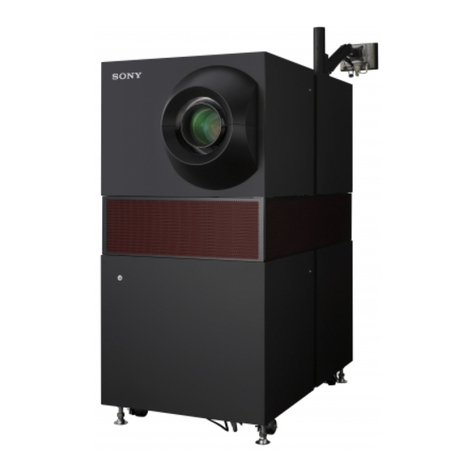
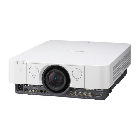
VPL-FHZ700L
Table of Contents
Manual Structure
Purpose of this manual............................................................ 3 (E)
Related manuals...................................................................... 3 (E)
Trademarks.............................................................................. 3 (E)
1. Service Overview
1-1. Precautions for Service Personnel.............................1-1 (E)
1-2. Appearance Figure ....................................................1-1 (E)
1-3. Precaution for Transport............................................1-2 (E)
1-4. Board Location..........................................................1-3 (E)
1-5. Tightening Torque .....................................................1-4 (E)
1-6. Disassembly ..............................................................1-5 (E)
1-6-1. Filter Holder Assembly....................................1-9 (E)
1-6-2. Top Cover Assembly/HA Board ....................1-10 (E)
1-6-3. GC Board/DC Fan (For the Exhaust of
Laser Source Unit (F)) ................................... 1-12 (E)
1-6-4. T Board/V Board............................................1-14 (E)
1-6-5. B Board/QA Board.........................................1-15 (E)
1-6-6. C Board/M Board...........................................1-17 (E)
1-6-7. DC Fan (For PS Converter) ...........................1-19 (E)
1-6-8. DC Fan (For LD B)/Switching Regulator
(LD B)............................................................1-20 (E)
1-6-9. G Board (Power Unit)/HB Board/NF Board/
DC Fan (For Power Supply) .......................... 1-21 (E)
1-6-10. Laser Source Unit (F) ....................................1-22 (E)
1-6-11. NR Board ....................................................... 1-23 (E)
1-6-12. QB Board/QC Board...................................... 1-24 (E)
1-6-13. Optical Unit (F) Assembly.............................1-25 (E)
1-6-14. DC Fan (For the Air Intake of R PANEL/
G PANEL/B PANEL) ....................................1-26 (E)
1-6-15. QM Board ......................................................1-27 (E)
1-6-16. F Board (EMI Filter)......................................1-28 (E)
1-6-17. LD A Board (Switching Regulator) ...............1-29 (E)
1-6-18. DC Fan (For the Air Intake of Laser Source
Unit (F)) ......................................................... 1-30 (E)
1-6-19. PS Converter..................................................1-31 (E)
1-6-20. In-polarizer (R)/(G)/(B) Assembly ................ 1-32 (E)
1-6-21. Lens Shift Unit/Prism (F) Assembly/
SB Board........................................................1-33 (E)
1-6-22. Out-pre-polarizer (R)/(G)/(B) and
Out-polarizer (R)/(G)/(B) ..............................1-34 (E)
1-7. Installation/Removal of Optional Lens ...................1-35 (E)
1-7-1. Work Flow .....................................................1-35 (E)
1-7-2. Lens Shift Unit...............................................1-35 (E)
1-7-3. Removal of Back Correction Glass
Assembly .......................................................1-36 (E)
1-7-4. Installation of Lens Adaptor ..........................1-37 (E)
1-7-5. Installation/Removal of Optional Lens..........1-38 (E)
1-7-6. Focus Adjustment of Peripheral Area............1-39 (E)
1-8. Cleaning ..................................................................1-44 (E)
1-8-1. Cleaning of Optical Unit (F) Assembly .........1-44 (E)
1-8-2. Cleaning of In-polarizer (R)/(G)/(B)
Assembly .......................................................1-44 (E)
1-8-3. Cleaning of Illumination System Optical
Parts ...............................................................1-46 (E)
1-8-4. Cleaning of PS Converter, First Fly-eye Lens
and Second Fly-eye Lens...............................1-48 (E)
1-8-5. Cleaning of Total Reflection Mirror 3 ...........1-49 (E)
1-8-6. Cleaning of Prism (F) Assembly....................1-50 (E)
1-9. Service Mode (Network Volume)............................ 1-51 (E)
1-9-1. Outline ...........................................................1-51 (E)
1-9-2. Update Function............................................. 1-51 (E)
1-9-3. Event Trace Function ..................................... 1-54 (E)
1-9-4. Setup Function ............................................... 1-57 (E)
1-10. Web Password Change ............................................ 1-57 (E)
1-11. Location Information of the Labels......................... 1-58 (E)
1-12. Indicator Display.....................................................1-59 (E)
1-13. Circuit Description .................................................. 1-60 (E)
1-13-1. Video Signal Processing System....................1-60 (E)
1-13-2. Signal Generation Boards .............................. 1-60 (E)
1-13-3. Sensor Boards ................................................1-61 (E)
1-13-4. Power Boards.................................................1-61 (E)
1-14. Lead-free Solder......................................................1-62 (E)
2. Adjustments
2-1. Notes on Servicing ....................................................2-1 (E)
2-2. Procedure When Replacing the Parts........................2-1 (E)
2-2-1.
Optical Unit (F) Assembly................................2-1
(E)
2-2-2. Prism (F) Assembly .........................................2-1 (E)
2-2-3. B Board............................................................2-2 (E)
2-2-4. QB Board ......................................................... 2-2 (E)
2-2-5. Laser Source Unit (F) ......................................2-2 (E)
