Sony VPL-FHZ700L User manual

4-544-271-13 (1)
© 2014 Sony Corporation
Data
Projector
Operating Instructions
Before operating the unit, please read this manual and supplied Quick Reference Manual
thoroughly and retain it for future reference.
VPL-FHZ700L

2Table of Contents
Table of Contents
Overview
Location and Function of Controls .... 3
Main Unit ..................................... 3
Terminals ...................................... 4
Remote Commander and Control
Panel .......................................... 5
Preparation
Connecting the Projector ................... 8
Connecting a Computer ................ 8
Connecting Video Equipment ...... 9
Connecting an External
Monitor ................................... 11
Connecting to HDBaseT™
equipment ................................ 11
Projecting/Adjusting an
Image
Projecting an Image ......................... 14
Adjusting the Focus, Size, and
Position of the Projected
image ....................................... 15
Turning Off the Power ................ 19
Adjustments and Settings
Using a Menu
Using a MENU ................................ 21
The Picture Menu ............................. 22
The Screen Menu ............................. 24
The Function Menu .......................... 27
The Operation Menu ........................ 28
The Connection/Power Menu .......... 29
The Installation Menu ...................... 32
The Information Menu .....................35
Network
Using Network Features ...................36
Displaying the Control Window of
the Projector with a Web
Browser ...................................36
Confirming the Information
regarding the Projector ............37
Operating the Projector from a
Computer .................................37
Using the e-mail report
Function ...................................37
Others
Indicators ..........................................39
Messages List ...................................40
Troubleshooting ................................41
Cleaning the Air Filter ......................43
Installing the Optional Adaptor ........45
Specifications ...................................46
Projection Distance and Lens Shift
Range ............................................53
Dimensions .......................................57
Index .................................................61

3
Location and Function of Controls
Overview
BOverview
Location and Function of Controls
aLens (not supplied) (page 47)
bFront panel
cAir filter cover (page 43)
dVentilation holes (intake)
eVentilation holes (exhaust)
Do not place anything near the ventilation
holes as this may cause internal heat
buildup. Do not place your hand near the
ventilation holes (exhaust) and the
circumference as this may cause injury.
fON/STANDBY indicator
(page 39)
gWARNING indicator (page 39)
hControl panel (page 5)
iTerminals (page 4)
jOptional adaptor slot (page 45)
Install an optional adaptor (not
supplied).
kRemote control receiver
The remote control receivers are located
at the front and rear of the projector.
lRear feet (adjustable) (page 16)
mAntitheft lock
Connects to an optional antitheft cable
manufactured by Kensington.
For details, visit the Kensington’s web
site.
http://www.kensington.com/
nAntitheft bar
Connects to a commercially available
antitheft chain or wire.
Main Unit
1276qa85
qd 9 0
Caution

4Location and Function of Controls
Input (page 8)
aINPUT A
Video: RGB/YPBPRinput terminal
(RGB HD VD/YPBPR)
bINPUT B
Video: RGB input terminal (RGB)
cINPUT C
Video: DVI-D input terminal (DVI-D)
dINPUT D
Video: HDMI input terminal (HDMI)
eINPUT E
Video: Optional adaptor slot*
fS VIDEO (S VIDEO IN)
Video: S video input terminal
gVIDEO (VIDEO IN)
Video: Video input terminal
* Regarding attachable optional adaptor,
consult with qualified Sony personnel.
Output (page 11)
hOUTPUT
Video: Monitor output terminal
(MONITOR)
This terminal outputs the image. Output as a
computer signal input from the RGB input
terminal (INPUT A, INPUT B) or a video
signal input from the YPBPRinput terminal
(INPUT A).
Others
iRS-232C terminal
RS-232C compatible control terminal
jLAN terminal (page 36)
kCONTROL S input terminal (DC
power supply) (CONTROL S IN
PLUG IN POWER)
Connects to the CONTROL S output
terminal on the supplied Remote
Commander with a connecting cable
(stereo mini plug (not supplied)) when
using it as a wired Remote Commander.
You do not need to install batteries in the
Remote Commander, as the power is
supplied from this terminal.
lCONTROL S output terminal
(CONTROL S OUT)
For coupling control of multiple
projectors with the wired Remote
Commander.
mAC IN (-) socket
Connects the supplied AC power cord.
Terminals
S VIDEO IN
LAN
INPUT E
RS-232C CONTROL S
VIDEO IN
INPUT B RGB INPUT C DVI-D
PLUG INPOWER
IN OUT
R/PRG/Y HD VD OUTPUT
MONITOR
INPUT D HDMI
B/PB
INPUT A
6
q
d
q
;
9q
a
5q
s
723 4
18
Note
Note

5
Location and Function of Controls
Overview
Remote Commander
Control Panel
aTurning on the power/Going to
standby
?(On) key
1(Standby) key
bSelecting an input signal
(page 14)
INPUT key (main unit)
Direct input select keys (Remote
Commander)
The F key is not provided in this
projector.
cOperating a menu (page 21)
ENTER /V/v/B/b(arrow) keys
MENU key
RETURN key
RESET key
dAdjusting the image (page 15)
FOCUS key
Use this key when attaching the power
focus lens.
ZOOM key
Use this key when attaching the power
zoom lens.
LENS SHIFT/SHIFT key
ASPECT key (pages 24, 26)
Changes the aspect ratio of the projected
image.
KEYSTONE key (page 16)
PATTERN key (page 16)
APA (Auto Pixel Alignment) key*
Automatically adjusts a picture to its
clearest while a signal is input from a
computer. You can cancel the adjustment
by pressing the APA key again while
adjusting.
*Use this key when inputting a computer
signal via the RGB input terminal
(INPUT A, INPUT B).
eUsing various functions during
projecting
D ZOOM (Digital Zoom) +/– key*1
Enlarges a portion of the image while
projecting.
1Press the D ZOOM + key to display
the digital zoom icon on the projected
image.
Remote Commander and Control Panel
ECO
MODE
ENTER
MENU
SHIFT ZOOM
FOCUS
INPUT
312
46
Note

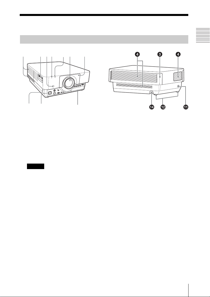
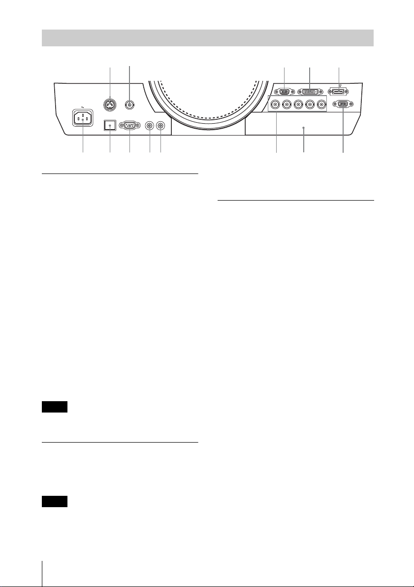
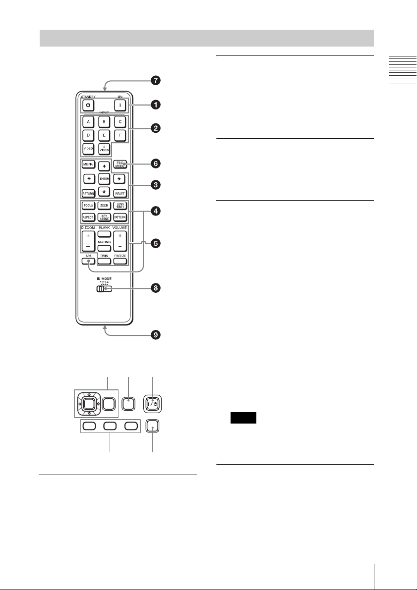
6Location and Function of Controls
2Press the V/v/B/bkeys to move the
digital zoom icon to the point on the
image you wish to enlarge.
3Press the D ZOOM + key or the D
ZOOM – key repeatedly to change the
enlargement ratio. The image can be
enlarged up to 4 times.
Press the RESET key to restore the
previous image.
TWIN (Twin Picture) key
You can project the images from two
input signals on the screen as a main
picture and subpicture at the same time.
To switch between one and two pictures,
press the TWIN key on the Remote
Commander.
You can select the image to project to the
main picture.
The subpicture is preset to display the
image from INPUT B.
For details on combinations of input
signals, see “Combinations of Input
Signals” on page 52.
• When displaying two pictures, the ?(On)
key, 1(standby) key, INPUT key, and
BLANK key are available.
• When “Screen Aspect” (page 33) is set
to “4:3,” the two picture function is not
available.
• When displaying two pictures, the input
signal icon does not appear in the
input select window (page 14).
• Picture settings set for one picture may
not be reflected as two pictures.
BLANK key
Cuts off the image. Press again to restore
the image.
MUTING key
This function is not provided in this
projector.
VOLUME +/– key
This function is not provided in this
projector.
FREEZE key*2
Pauses a projected image. Press again to
restore the image.
*1: Use this key when inputting a
computer signal. But it may not be
enabled, depending on the resolution
of the input signal and when
displaying two pictures.
*2: Use this key when inputting a
computer signal.
fSetting the energy–saving mode
easily
ECO MODE key
Energy-saving mode can be set easily.
Energy-saving mode consists of “Light
Output Mode,” “Constant Brightness,”
“With No Input,” “With Static Signal”
and “Standby Mode.”
1Press the ECO MODE key to display
the ECO Mode menu.
2Press the V/vkey or ECO MODE key
to select ECO or User mode.
ECO: Sets each mode to the optimum
energy-saving value.
Light Output Mode: Standard
Constant Brightness: On
With No Input: Standby
With Static Signal: Light
Notes
One picture display
TWIN key
Two pictures display
(A) Main picture (B) Subpicture
Notes
ECO
User
Sel Back
ECO Mode
ECO Mode Menu

7
Location and Function of Controls
Overview
Dimming
Standby Mode: Low
(go to step 6)
User: Sets each item of the energy-
saving mode menu as you desire
(go to step 3).
3Select “User” then press the bkey.
The setting items appear.
4Press the V/vkey to select the ECO
Mode item then press the b key or the
ENTER key.
5Press the V/vkey to select the setting
value.
6Press the RETURN key to restore the
previous image.
For details on ECO Mode settings, see
“Light Output Mode”, “With No Input”,
“With Static Signal” and “Standby
Mode” on the Connection/Power menu
(page 29).
Others
gInfrared transmitter
hID MODE 1/2/3/4 switch
(page 28)
Sets an ID mode of the Remote
Commander. If you assign a different ID
number to each projector when multiple
projectors are used, you can control only
the projector with the same ID mode as
that of the Remote Commander.
iCONTROL S output terminal
Connects to the CONTROL S input
terminal on the projector with a
connecting cable (stereo mini plug (not
supplied)) when using the Remote
Commander as a wired one.
You do not need to install batteries in the
Remote Commander, as the power is
supplied from the projector.
About Remote Commander operation
• Direct the Remote Commander toward the
remote control receiver.
• The shorter the distance between the
Remote Commander and the projector is,
the wider the angle within which the
Remote Commander can control the
projector becomes.
• If there is any obstruction between the
Remote Commander and the remote
control receiver on the projector, the
projector may not be able to receive
signals from the Remote Commander.
Light Output Mode Standard
Constant Brightness Off
Auto Power Saving
With No Input Off
With Static Signal Light Dimming
Standby Mode Standard
Sel Back
User
Set

8Connecting the Projector
BPreparation
Connecting the Projector
• Turn off all equipment before making any connections.
• Use the proper cables for each connection.
• Insert the cable plugs firmly; Loose connections may reduce performance of picture signals or
cause a malfunction. When pulling out a cable, be sure to grip it by the plug, not the cable itself.
• For more information, refer also to the instruction manuals of the equipment you are connecting.
Connection with a computer is explained for each input signal.
INPUT A
For connection when there is a long distance between a computer and the projector.
INPUT B
For connecting a computer with an RGB output terminal.
It is recommended that you set the resolution of your computer to 1920 × 1200 pixels for the external
monitor.
Notes
Connecting a Computer
Note
Mini D-sub 15-pin – BNC cable
(not supplied)
RGB output
terminal
Computer
Mini D-sub 15-pin
cable (not supplied)
RGB output
terminal
Computer

9
Connecting the Projector
Preparation
INPUT C
For connecting a computer with a DVI-D output terminal.
INPUT D
For connecting a computer with an HDMI output terminal.
• The HDMI terminal of this projector is not compatible with DSD (Direct Stream Digital) Signal
or CEC (Consumer Electronics Control) Signal.
• Be sure to use the HDMI cable with an HDMI logo.
Connections with a VHS videocassette recorder, DVD player, or BD player are explained for
each input signal.
S VIDEO IN
For connecting video equipment with an S-video output terminal.
Notes
Connecting Video Equipment
INPUT C DVI-D
DVI-D cable
(not supplied)
DVI-D output
terminal
Computer
HDMI cable
(not supplied)
HDMI output
terminal
Computer
S video cable (not supplied)
S video output
terminal
Video equipment

10 Connecting the Projector
VIDEO IN
For connecting video equipment with a video output terminal.
INPUT A
For connection when there is a long distance between the video equipment and projector.
INPUT D
For connecting video equipment with an HDMI output terminal.
• The HDMI terminal of this projector is not compatible with DSD (Direct Stream Digital) Signal
or CEC (Consumer Electronics Control) Signal.
• Be sure to use the HDMI cable with an HDMI logo.
Notes
Video – BNC cable
(not supplied)
Video output
terminal
Video equipment
Component – BNC cable (not supplied)
Video equipment
YPBPRoutput
terminal
HDMI cable
(not supplied)
Video equipment
HDMI output
terminal

11
Connecting the Projector
Preparation
To fix the HDMI cable
Fix the cable to the cable tie holder at the bottom of the projector, using a commercially
available cable tie, as in the illustration.
Use a cable tie of less than 1.9 mm × 3.8 mm in thickness.
OUTPUT
Projected images can be output to display equipment such as a monitor.
This terminal outputs the image. Output as a computer signal input from the RGB input terminal
(INPUT A, INPUT B) or a video signal input from the YPBPRinput terminal (INPUT A).
• You can connect HDBaseT equipment by attaching the Digital Interface Adaptor BKM-PJ10
(not supplied).
• When the Digital Interface Adaptor BKM-PJ10 (not supplied) is attached to the main unit,
image transmission to the main unit, LAN communication, and RS-232C control are enabled
with the commercially available HDBaseT transmitter. Not compatible with voice
communication and power connection.
Connecting an External Monitor
Bottom of the projector
Cable tie
(commercially available)
Cable tie holder
Note
Connecting to HDBaseT™ equipment
Mini D-sub 15-pin cable
(not supplied)
RGB input
terminal
Display equipment

12 Connecting the Projector
• Use a straight LAN cable (commercially-available) with a shield of CAT5e or CAT6 to
connect the main unit and HDBaseT equipment.
Connecting to the computer
INPUT E
Connecting to video equipment
INPUT E
Connect HDBaseT transmitter and the main unit directly without a hub or router.
Note
Computer
HDMI output
terminal
HDMI cable (not supplied)
HDBaseT transmitter
Video equipment
HDMI output
terminal
HDMI cable (not supplied)
HDBaseT transmitter

13
Connecting the Projector
Preparation
Connecting to network equipment
When using network features, be sure to check if “LAN Setting” is set to “via HDBaseT” (page 29).
Note
Computer
LAN
terminal
Wired connection
LAN cable (straight type)
(not supplied)
Hub, Wireless router
HDBaseT transmitter
Tablet PC/Smartphone
Computer
Wireless connection

14 Projecting an Image
BProjecting/Adjusting an Image
Projecting an Image
The size of a projected image depends on the distance between the projector and screen. Install
the projector so that the projected image fits the screen size. For details on projection distances
and projected image sizes, see “Projection Distance and Lens Shift Range” (page 53).
1Plug the AC power cord into a wall
outlet.
2Connect all equipment to the projector
(page 8).
3Turn on the projector.
Press the ?/1key on the main unit or the
?key on the Remote Commander.
4Turn on the connected equipment.
5Select the input source.
Press the INPUT key on the projector to
display the input select window. Press
the INPUT key repeatedly or the V/v
key to select an image to be projected.
The signal icon appears on the right
side in the input select window when a
signal is input.
You can select the input source using
Direct input select keys on the Remote
Commander (page 5).
6Switch your computer to output to
external display by changing your
computer’s setting.
How to switch the computer to output to
the projector varies, depending on the
type of computer.
(Example)
7Adjust the focus, size, and position of
the projected image (page 15).
Computer
Video equipment
Projector
Wall outlet
1
23
5
4
5
6
Input select window
+

15
Projecting an Image
Projecting/Adjusting an Image
Adjusting the Focus, Size, and Position of the Projected image
Focus Size (Zoom) Position (Lens shift)
When attaching the Electric
focus lens
Press the FOCUS key on the
projector or the Remote
Commander then press the B/
bkey (or V/vkey) to adjust
the focus.
When attaching the Manual
focus lens
Turn the Focus Ring to adjust
the focus.
When attaching the Electric
zoom lens
Press the ZOOM key on the
projector or the Remote
Commander then press the B/
bkey (or V/vkey) to adjust
the size.
When attaching the Manual
zoom lens
Turn the Zoom Ring to adjust
the size.
Press the LENS SHIFT/SHIFT
key on the projector or the
Remote Commander then press
the V/v/B/bkey to adjust the
position.
To return the lens to the center
position of the projected image
Press the RESET key on the
Remote Commander while
adjusting.

16 Projecting an Image
Adjusting the tilt of the projector
with the rear feet (adjustable)
When the projector is installed on an uneven
surface, you can adjust using the rear feet
(adjustable). To correct any trapezoidal
distortion of the projected image, use the
Keystone correction feature (pages 16, 32).
You can also broaden the adjustment range
by removing the nuts from the rear feet
(adjustable).
• Be careful not to let the projector down on
your fingers.
• Do not push hard on the top of the projector
with the rear feet (adjustable) extended. It
may cause a malfunction.
• Keystone adjustment is an electronic
correction. Consequently the image quality
may deteriorate.
Displaying a pattern for adjusting
an image
You can display a pattern for adjusting the
projected image with the PATTERN key on
the Remote Commander. Press the
PATTERN key again to restore the previous
image.
Correcting for trapezoidal
distortion of the projected image
(Keystone adjustment)
If the screen is tilted, or you are projecting
from an oblique angle, perform keystone
adjustment.
If the projected image is
trapezoidally-distorted in the vertical
plane
1Press the KEYSTONE key on the
Remote Commander once or select “V
Keystone” in the Installation menu to
display the adjustment menu.
2Adjust the value using V/v/B/b.
The higher the setting, the narrower the
top of the projected image. The lower
the setting, the narrower the bottom of
the projected image.
Press the RESET key to restore the
projected image before adjustment.
If the projected image is
trapezoidally-distorted in the lateral
plane
1Press the KEYSTONE key on the
Remote Commander twice, or select
“H Keystone” in the Installation menu
to display the adjustment menu.
2Adjust the value using V/v/B/b.
The higher the setting, the narrower the
right side of the projected image. The
lower the setting, the narrower the left
side of the projected image.
Notes
Increase setting
Decrease setting

17
Projecting an Image
Projecting/Adjusting an Image
Press the RESET key to restore the
projected image before adjustment.
• Keystone adjustment is an electronic
correction. Consequently the image quality
may deteriorate.
• Depending on the position adjusted with the
lens shift feature, using the Keystone feature
may change the aspect ratio of the original
image, or the projected image may be
distorted.
• If keystone correction is performed using the
KEYSTONE key, the Warp correction
feature (if enabled) will be canceled.
Correcting image twist (Warp
correction feature)
You can correct image twist with the warp
correction feature.
1Press the KEYSTONE key on the
Remote Commander three times, or
select “Warping” in the Installation
menu, then select “Adjust.”
The guide is displayed.
Selecting the corner(s) of the image
to be corrected
1Move xusing V/v/B/bto select the
corner you want to correct.
2Press the ENTER key.
The cursor appears.
3Adjust the position of the corner you
want to correct, using V/v/B/b.
Press the RESET key to restore the
projected image before adjustment.
Correcting deflection 1– left/right
sides of the image
1Move xusing V/v/B/bto select the
side you want to correct.
2Press the ENTER key.
The cursor appears.
Notes
Decrease setting
Increase the setting
Adjust using this cursor

18 Projecting an Image
3You can adjust the deflection of the
side, using V/v/B/b.
You can adjust the center point of
deflection using V/v. For the range of
deflection, use B/b. You can adjust the
left/right side independently.
Press the RESET key to restore the
projected image before adjustment.
Correcting deflection 2– top/bottom
sides of the image
1Move xusing V/v/B/bto select the
side you want to correct.
2Press the ENTER key.
The cursor appears.
3You can adjust the deflection of the
side, using V/v/B/b.
You can adjust the center point of
deflection using B/b. For the range of
deflection, use V/v. You can adjust the
top/bottom independently.
Press the RESET key to restore the
projected image before adjustment.
Setting the blending function to
project from multiple projectors
1Install the projectors.
Input a pattern, etc., to adjust the
projected positions from multiple
projectors.
Set a different ID mode for each
projector (page 28).
Adjust using this cursor Adjust using this cursor

19
Projecting an Image
Projecting/Adjusting an Image
2Enable the Edge Blending function.
Display the main menu to set “Edge
Blending” to “On” in the Installation
menu.
3Set the position of blending.
Choose the position (top/bottom/left/
right) for blending.
4Assign the blending width.
Set the blending width according to the
overlapping range for the source signal.
5Adjust using “Zone Black Level Adj.”
Adjust each correction zone by “Zone
Black Level Adj.” for the most uniform
black level between each zone.
During this adjustment, a black image is
automatically projected.
6Set “Blend Gamma.”
Select the gamma mode in which the
overlapping of images is least
noticeable.
• The procedure shown above is for general
guidance. Your own installation may vary
according to the situation.
• In case of multiple projectors, use the color
matching function (page 34) to adjust for
differences in color and brightness.
Note that more detailed adjustment for Edge
Blending is possible using a PC application.
For more details, consult with qualified Sony
personnel.
• When multiple projectors are set up in a line,
the temperature inside the projectors may
increase due to exhaust vent proximity, and
an error indication may result.
In this case, space the projectors farther apart
and/or install deflection partitioning between
them.
For more details, consult with qualified Sony
personnel.
1Press the ?/1key on the main unit or
the 1key on the Remote Commander.
The projector starts shutdown and turns
off. If you press the ?/1key on the main
unit or the ?key on the Remote
Commander within 5 seconds again,
shutdown is cancelled.
2Unplug the AC power cord from the
wall outlet.
To turn off without displaying
confirmation message
Press and hold the ?/1key on the main unit
for a few seconds (page 40).
Assign the position and width here.
Blend Gamma
correction
Notes
Turning Off the Power

20 Projecting an Image
ECO gauge
This gauge indicates the current
effectiveness of the projector’s ECO
function. (For details on the ECO function,
see “ECO MODE key” (page 6) and “ECO”
(page 29).)
The leaf icons are displayed when the
projector is shut down. The number of
displayed icons varies according to how
much energy is saved as a result of using the
ECO function.
ECO gauge
Other manuals for VPL-FHZ700L
3
Table of contents
Other Sony Projector manuals

Sony
Sony VPL-PX41 User manual

Sony
Sony VPD-LE100 User manual

Sony
Sony CPJ-D500 - SVGA LCD Projector User manual

Sony
Sony VPL-VW95ES User manual

Sony
Sony SuperLite VPL-CS7 User manual

Sony
Sony Xperia Touch G1109 User manual

Sony
Sony Supersmart VPL-PX15 User manual

Sony
Sony VPL-HW45 Service manual

Sony
Sony VPL-FHZ120L Service manual

Sony
Sony VPL-FX500L User manual

Sony
Sony VPL-VW870ES User manual

Sony
Sony VPL-FHZ55 User manual

Sony
Sony HDMI VPL-FE40 User manual

Sony
Sony VPL-SX536M Guide

Sony
Sony VPL-DW125 User manual

Sony
Sony VPL-VW1000ES User manual

Sony
Sony VPL-DX10 User manual

Sony
Sony VPL-EX281 User manual

Sony
Sony VPL-ES3 Service manual

Sony
Sony VPLFH31/B User manual