Sony IPELA SNC-VM772R User manual

Network Camera
Installation Manual
Before operating the unit, please read this manual thoroughly
and retain it for future reference.
SNC-VM772R
C-200-100-11 (1)
© 2015 Sony Corporation

2
Table of Contents
About the Manuals .................................................... 2
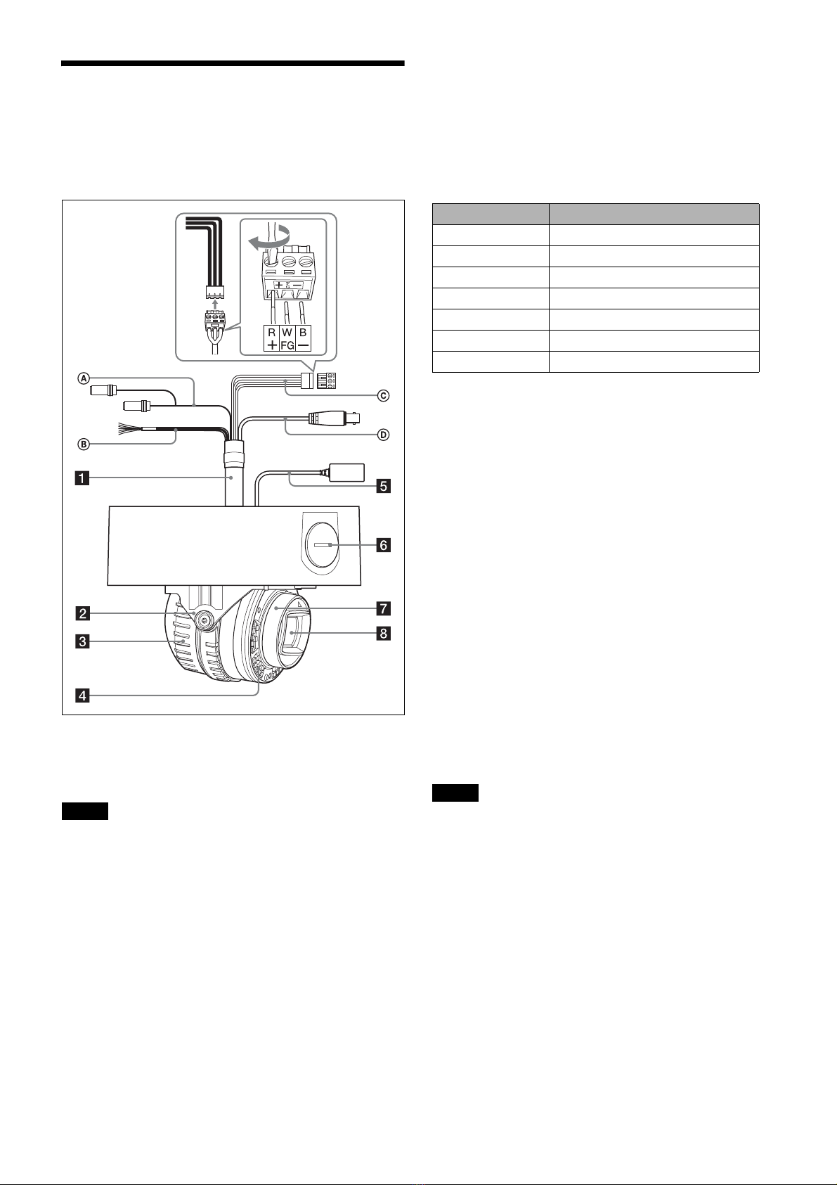
Location and Function of Part ................................. 3
Preparations .............................................................. 7
Change connections and cable wiring ................... 7
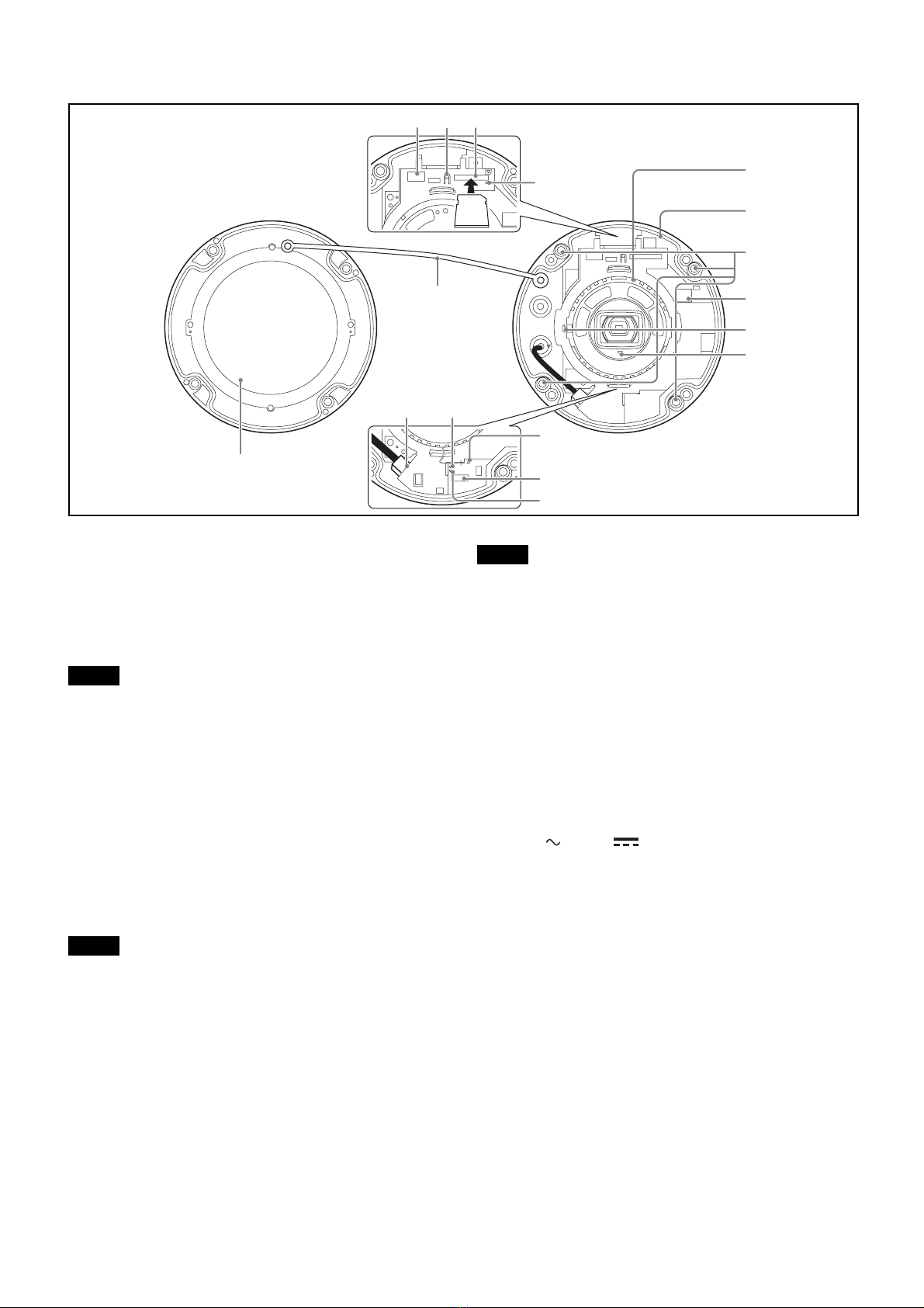
Installation ................................................................. 8
Deciding the Installation Location of the
Camera ................................................................. 8
Installing the Camera ............................................. 9
Installing the Camera (if you use a commercially
available LAN cable) ......................................... 10
Installing the Camera (If you use the conduit hole
on the side) ......................................................... 10
Installing the Camera (if you use a multi connector
cable) .................................................................. 10
Adjustment of the Shooting Direction and
Range ................................................................. 10
Attaching the Dome Casing ................................. 11
Important precautions .......................................... 12
Connection ............................................................... 13
Connecting to the Network .................................. 13
Connecting the Power Source .............................. 13
Connecting to 12 V DC or 24 V AC source ........ 13
Connecting to the power supply equipment
pursuant to IEEE802.3af .................................... 13
Connecting the I/O Cable .................................... 13
Assigning the IP address ........................................ 14
Specifications ........................................................... 15
About the Manuals
Read This First (supplied)
The Read This First manual describes the URL of the
download site and the QR code. Be sure to read it.
Safety Regulations (supplied)
The Safety Regulations describes the secure usage of
camera. Be sure to read it.
Installation Manual (this document)
This Installation Manual describes the names and
functions of parts and controls of the Network Camera,
gives connection examples and explains how to set up the
camera. Be sure to read the Installation Manual before
operating.
User’s Guide/Application Guide/SNC
toolbox mobile Application Guide (Web)
The User’s Guide describes how to set up the camera and
how to control the camera via a Web browser.
These guides describe the following methods:
• How to control the camera via a web browser
• How to setup the camera
• How to adjust the view angle of the camera using a
smartphone or tablet
After installing and connecting the camera correctly
following the instructions in the Installation Manual,
operate the camera by referring to these guides.

3
Location and Function of
Part
Side
The figure shows the camera without the dome casing.
aMulti connector cable (supplied)
Not connected to the camera at the factory.
Note
Using a device other than the recommended devices may
cause a failure or malfunction.
AAudio cable
The connector with the longer cable (SP) is used for the
line output connector, and the shorter cable (MIC) is used
for the microphone/line input connector.
Switch the microphone input and the line input in the
Video/Audio menu.
For details of the settings, refer to the User’s Guide.
• SP terminal (minijack, monaural)
Not used with this unit.
• MIC terminal (minijack, monaural)
Connect a commercially available microphone. This
jack supports pluginpower microphones.
BI/O (Input/Output) cable
This cable is provided with two sensor inputs and two
alarm outputs.
The wires of the cable control the following signals.
◆For details on each function and required settings, see
the User’s Guide.
◆For the wiring, see “Connecting the I/O Cable” on page
13.
CPower input cable (supplied and connected
to the camera at the factory)
Connect this cable to a 24 V AC or 12 V DC power supply
system.
You can screw an extension cable in the connector tip
attached at the end of the cable. When you use the power
input cable, connect GND to the center of the 3-pin
connector (FG).
DBNC cable
Not used with this unit.
bBase (PAN)
cCamera block
dInfrared LED
Irradiates infrared light.
Notes
• Do not look at the infrared LED for a long time.
• Images may be dark if irradiated at a high temperature
environment.
eLAN cable (RJ-45) (supplied and connected
to the camera at the factory)
Connect this cable to a hub or computer on the 10BASE-T
or 100BASE-TX network using a commercially available
network cable (UTP, category 5).
Color of wire Name
Red Sensor In 1+
White Sensor In 2+
Black Sensor In – (GND)
Yellow Alarm Out 1+
Brown Alarm Out 1–
Green Alarm Out 2+
Blue Alarm Out 2–

4
fSide conduit hole (3/4inches NPT or M27
(2.0 mm (3/32 inches)-pitched, hole diameter
ø27 mm (1 1/8inches)))
Connect a pipe to this hole. There is a conduit hole on the
side of the camera unit. The conduit hole cover is installed
in the side conduit hole at the factory.
Remove the cover as needed and connect the pipe to the
hole.
An M25 cable gland can be connected to the hole by
removing the nut inside the camera unit.
Note
Take care not to trap the cables between the camera and the
ceiling or the wall. If the cable is trapped, it may cause a
fire or electric shock due to breaking.
gCamera head
hLens

5
Inside
aConnector dedicated to WLAN (Wireless LAN
terminal)
Attach a separately sold Sony product; USB Wireless LAN
Module IFU-WLM3 (hereafter WLAN module).
Use the module to view the angle adjustment when
installing the camera.
Notes
• When the WLAN module is mounted, the wired LAN is
not available.
• Using a device other than the specified devices may
cause a failure or malfunction.
• Do not attach the dome casing while attaching the
module to the connector.
• When using WLAN, use the camera at an outside air
temperature between 0°C to 40°C.
bSD OFF switch
By pressing the switch, the SD memory card can safely be
removed.
Note
After turning off the SD MOUNT indicator, the SD
memory card can be removed.
cSD card slot
This slot is used for separately sold SD memory cards.
Image data in the camera can be recorded to a memory card
by inserting it into the slot.
Align the notch of the memory card with the mark, and
gently insert the memory card to the slot until it clicks into
place.
This unit is compatible with the memory cards of SDXC
and SDHC standards only.
Note
For inquiries regarding verified SD memory cards, contact
your authorized Sony dealer.
dSD MOUNT indicator
When mounting the SD memory card, the indicator lights
up.
eCamera unit
fCamera unit mounting screws (four
positions)
Make sure to tighten the screws securely when installing
the camera.
g24 V / 12 V (power input) connector
Connect the power input cable in the supplied multi
connector cable.
hCamera block fixing screw (tilt) (one position)
First, point the camera block in the desired direction, then
tighten the screw to secure in place.
ifTOP mark
Indicates the image direction.
jReset switch
To reset the camera to the factory default settings, hold
down this switch with a pointed object and supply power
to the camera.
kAUDIO EXT CTRL (external control input/
output) connector
Connect the AUDIO and I/O cables in the supplied multi
connector cable.
5
6
7
8
9
q;
qa
qs
1
qh
23
4
qdqf
qg
Infrared LED

6
lNETWORK indicator (Green/Orange)
The indicator lights up or flashes when the camera is
connected to the network.
The indicator is off when the camera is not connected to
the network.
mPOWER indicator (Green/Orange)
When power is supplied to the camera, the camera starts
checking the system.
If the system is normal, this indicator lights up in green.
When only the built-in heater is working (the system is
stopped), the indicator lights up in orange.
nLAN network port (RJ-45)
Connect a commercially available network cable (UTP,
category 5) to communicate with a network or PoE*
system.
For details on connection, see the Instruction Manual of
the power supply equipment.
(*PoE + stands for Power over Ethernet. PoE is compliant
with IEEE802.3af)
oDome casing
The dome cover is made of polycarbonate. A waterproof
rubber gasket is provided on the joint surface to the unit.
pSafety cord
This cord prevents the dome casing from falling off the
unit.
Bottom
aRating label
Shows the name of this camera and its electric rating.
bNut (3/4inches NPT or M27 (2.0 mm (3/32
inches)-pitched))
cHDMI connector
Connect the commercially available HDMI cable.
Notes
• To prevent the HDMI cable disconnecting from the
camera (either by its own weight or an external force), it
is recommended to secure it with commercially available
retaining parts, etc.
• When using the HDMI cable, use it at an outside
temperature between 0 ºC to 50 ºC.
dVent filter
Note
Do not damage the filter and do not cover the hole of the
filter.
eSealing rubber
When attaching the supplied multi connector cable,
remove the rubber.
fGND
Ground the camera when you install it.
Tip
When connecting the GND from the power input cable, the
GND connection from the GND screw is not necessary.
Note
Use the supplied Screws 3(M4 × 8)
gTerminal rubber
By removing the terminal rubber, you can confirm the
HDMI connector. When you use the HDMI connector,
remove the rubber.
Note
When you remove the terminal rubber to use the HDMI
connector, the water-proof capability of the camera is lost.
Do not use the camera outdoors.
hFall-prevention strap
Connect to the brackets and prevent the camera from
falling.
iScrew
1 2
5
3
6
8
9
7
4

7
Preparations
Change connections and cable
wiring
The supplied LAN cable is connected to the camera at the
factory.
To change connections and cable wiring to suit your
requirements, perform the following steps.
◆When you route the cables from the side of the camera
unit, see “c) If you use the side conduit hole”.
a) If you use the camera with its factory setting
The preparation is completed.
b) If you use a commercially available LAN cable
Use a LAN cable with a cable diameter between ø5.5 mm
(7/32 inches) to ø6.5 mm (9/32 inches).
1Remove the dome casing. (See “Installing the Camera
- Step 1” on page 9.)
2Remove the supplied LAN cable. (b-1)
3Attach the sealing rubber to the LAN cable. (b-2)
Cut-off the supplied sealing rubber at the proper position,
and insert the cable into the rubber. (b-3)
Notes
• Do not pull the cable strongly. The cable may disconnect
from the connector.
• Waterproof the connection part between the cable and
the sealing rubber.
c) If you use the side conduit hole
1Remove the side conduit hole cover.
Note
When using a flanged pipe or cable gland, refer to
“Important precautions” (page 12).
d) If you use a multi connector cable (supplied)
When you use a cable other than the network cables, use
the multi connector cable (supplied).
1Remove the dome casing. (See “Installing the Camera
- Step 1” on page 9.)
2Remove the sealing rubber of the camera.
3Attach the multi connector cable (supplied) properly
to the hole which has been covered with the sealing
rubber.
Note
Water may enter if not attached properly.
4Connect the AC/DC and 10Pin (Audio, EXT CTRL)
cables to the connectors, and store cables in the hooks.
b-1 Press the rubber.
b-2
b-3
x
y
zReference position
x: cable diameter ø5.5 mm
(7/32 inches)
y: cable diameter ø6 mm
(1/4inches)
z: cable diameter ø6.5 mm
(9/32 inches)
Hook
Audio,
EXT
CTRL
24 V /
12 V

8
Installation
WARNING
• If you attach the camera in the height such as the wall or
the ceiling, etc., entrust the installation to an experienced
contractor or installer.
• If you install the camera at a height, ensure that the
installation location and its material are strong enough to
withstand a weight of 10 kg (22 lb 0.74 oz) or more, and
then install the camera securely. If the ceiling is not
strong enough, the camera may fall and cause serious
injury.
• To prevent the camera from falling, make sure to attach
the supplied fall-prevention strap.
• If you attach the camera to the ceiling, check
periodically, at least once a year, to ensure that the
connection has not loosened. If conditions warrant, make
this periodic check more frequently.
• Install the bracket and the camera unit to a clean, flat,
and level location that has no deformities. Otherwise,
installation may not be possible.
Deciding the Installation Location of
the Camera
After deciding the direction in which the camera will
shoot, make a hole of the appropriate size (within ø74 mm
(3 inches)) for the connecting cables using the supplied
template. Then, determine the four mounting hole
positions to install the bracket. The “O” mark indicates the
direction of the conduit hole (connected to the pipe) of the
camera unit.
Mounting screws
The supplied bracket is provided with eight ø4.5 mm
(3/16 inches) mounting holes. Install the bracket on a
ceiling or wall by tightening screws through four mounting
holes (83.5 mm (3 3/8inches) or 85.7 mm (3 3/8inches)-
pitched).
The required mounting screws differ depending on the
installation location and its material. (Mounting screws are
not supplied.)
Steel wall or ceiling: Use M4 bolts and nuts.
Wooden wall or ceiling: Use M4 tapping screws. The
panel thickness must be 15 mm (19/32 inches) or more.
Concrete wall: Use anchors, bolts and plugs suitable for
concrete walls.
Junction box: Use screws to match the holes on the
junction box.
WARNING
The required mounting screws differ depending on the
installation location and its material. If you do not secure
the camera with the appropriate mounting screws, the
camera may fall off.
Direction of conduit hole (connected to the pipe)
of the camera unit
85.7 (3 1/8)
83.5 (3 3/8)
46 (1 13/16)
Hole for
installing the
bracket
Hole for connecting cables
ø74 mm (3 inches)
Vertical marker
Unit: mm (inches)
46 (1
13
/
16
)
83.5 (3 3/8)
85.7 (3 1/8)

9
Installing the Camera
1
Remove the dome casing.
1Loosen the screws with the wrench (supplied).
2Pull up and remove the dome casing. When the screw
catches on the screw hole, pull up the screw.
2
Install the supplied bracket on the ceiling or wall.
“O” mark indicates the direction of the conduit hole
(connected to the pipe) of the camera unit. For the screws
to be used, refer to “Mounting screws” (page 8).
3
Attach the fall-prevention strap to the bracket.
1Hang the strap matching the position between the
bracket and the conduit hole as shown in figure. 3.
2Rotate the strap 90 degrees to enable the fall-
prevention function.
4
Wire the cables on the bottom.
Wire the supplied LAN cable.
5
Attach the camera unit to the bracket temporarily.
Align the “O” mark of the bracket and “O” mark of the
camera unit, and insert the camera unit into the bracket
until it clicks into place. The camera unit is temporarily
attached to the bracket, and the attached state is as it is even
if you release your hands from the camera unit.
Note
The camera unit is temporarily attached. The temporary
attachment may come off due to vibrations or shocks.
After attaching temporarily, secure the camera unit to the
bracket with the camera unit mounting screws
immediately.
1,2
1
2
1
Wrench
Screw (4 positions)
2
Ceiling
Bracket (supplied)
3
Ceiling
Ceiling
Side
conduit
hole
5,6
“O” mark
Screw positions

10
6
Attach the camera unit to the bracket with the camera
unit mounting screws (four screws).
Tighten the four mounting screws attached to the unit, and
fix the camera unit to the bracket.
Note
Water may enter if not attached properly.
Installing the Camera (if you use a
commercially available LAN cable)
1
Perform the steps 1 to 3 of “Installing the Camera”
(page 9).
2
Adjust the LAN cable to the camera unit.
Attach the LAN cable with the sealing rubber to the hole
with the mark of the camera unit.
3
Perform the steps 5 to 6 of “Installing the Camera”
(page 9).
4
Cut the cable to a proper length and attach the network
connector at the end of the cable.
5
Connect the cable to the network port.
Note
Water may enter if not attached properly.
Installing the Camera (If you use the
conduit hole on the side)
1
Perform the steps 1 to 3 of “Installing the Camera”
(page 9).
2
Wire the cables on the bottom.
1Insert the cables to the pipe and conduit hole.
2Wire the cables.
3Insert the pipe to the conduit hole.
3
Perform the steps 5 to 6 of “Installing the Camera”
(page 9).
Note
When using a flanged pipe or cable gland, refer to
“Important precautions” (page 12).
Installing the Camera (if you use a
multi connector cable)
1
Perform the steps 1 to 3 of “Installing the Camera”
(page 9).
2
Wire the cables on the bottom.
Wire the supplied LAN cable or multi connector cable as
required.
3
Perform the steps 5 to 6 of “Installing the Camera”
(page 9).
Adjustment of the Shooting
Direction and Range
You can adjust the directions of pan, tilt, and rotation.
There is no fixed screw for the pan and rotation directions.
fTOP mark indicates the upper direction of the image.
You can invert the image by using the setting menu.
Press the sealing rubber.
fTOP
mark
Pan
Tilt
Rotation
Tilt fixing
screw

11
1
Adjust the camera to turn the lens in the desired
direction. (Pan/Tilt/Rotation)
Adjust the angle of view or focus while viewing the
images, and decide the range in which the camera will
shoot.
2
Tighten the tilt fixing screw.
Tighten the screw with the tightening torque that is
85 N·cm ± 10 N·cm.
Notes
• Tightening the tilt fixed screw with force more than
specified may cause a damage or deformation of the
screw.
• By attaching the dome casing to the camera, slight
blurring may occur. In this case, perform the focus
adjustment by using the system menu. For details, refer
to “User's Guide”.
• When attaching the dome casing, the case may be appear
on the images depending on zooming, tilting or rotation.
Distortion other than the specified optical area of the
dome cover also may be appear on the images.
Adjustment using the SNC toolbox mobile
You can adjust the view angle easily by installing the SNC
toolbox mobile to a smartphone or a tablet.
When the separately sold IFU-WLM3 is mounted to the
camera, the following SSID is displayed in the Wi-Fi
configuration of the smartphone. Select the SSID.
SNC-(MAC address of IFU-WLM3)
The default password is as follows:
Password: T8qUDTUuFyb8a
For details, refer to the SNC toolbox mobile Application
Guide on the Web site.
Attaching the Dome Casing
Fix the dome casing and the camera unit
Align four screw holes on the dome casing with those on
the camera unit, and tighten four dome casing fixed screws
with the supplied wrench to secure the dome casing.
Note
Make sure the safety cord does not get caught between the
dome casing and camera unit.

12
Important precautions Despite the fact that this unit is rated IP66, this section
includes important precautions to prevent any malfunction
caused by condensation and/or water ingress. Read the
precautions below thoroughly before installing the unit.
• Make sure to install the camera unit so that the surface of
the connection cables (including connectors) does not
water. Or waterproof should be performed properly.
Otherwise, there may be a risk that water enters the unit
through these cables.
• Install the bracket and the camera on an even ceiling or
wall, etc. (1)
• Install the camera properly, using the screws, while
referring to the Installation Manual. (2)
• Use a pipe/joint of 3/4inches-14 NPT or M27 (2.0 mm
(3/32 inches)-pitched) with a thread length of 12 mm or
less, and an internal diameter is at least ø20 mm (13/16
inches). (3)
• When connecting a cable gland to the side conduit hole,
use the cable gland which has following conditions:
– connectable to the side conduit hole with an opening of
ø27 mm (1 1/8inches)
– a thread length of 12 mm (1/2inches) or less
– waterproof performance suited to the installation
environment
Notes on assembly
• Make sure that do not get caught the fall-prevention cord
and cables between the dome casing and camera unit.
(4)
• Before attaching the dome casing to the camera unit,
make sure the waterproof rubber gasket is clean and fits
in the groove of the joint surface properly. (5)
• When using a rubber gasket or the multi connector cable,
make sure the rubber portion is clean and attach to the
camera unit properly. (6)
4
5
6
3
12 mm (1/2inches) or less
at least ø20 mm

13
Connection
Connecting to the Network
Connect the LAN port of the camera to a router or hub in
the network using a commercially available network cable
(not supplied).
Connecting the Power Source
There are three ways to supply the power source to this
camera, as follows.
• DC 12 V
•AC24V
• Power supply equipment pursuant to IEEE802.3af
(PoE* system)
* PoE means Power over Ethernet.
Notes
• Do not turn off the camera immediately after turning it
on. Wait for at least five minutes before turning off the
camera.
• Do not connect the power input cable if power is
supplied by a PoE system.
Connecting to 12 V DC or 24 V AC
source
Connect the power input cable of the camera to a 12 V DC
or 24 V AC source.
• Use a 12 V DC or 24 V AC source isolated from 100 to
240 V AC. Each usable voltage range is as follows.
(Assured range of the voltage the camera is receiving
(receiving-end voltage))
12 V DC: 10.8 V to 13.2 V
24 V AC: 19.2 V to 28.8 V
– In the USA, The product shall be powered by a UL
Listed Class 2 Power Supply Only.
– In Canada, The product shall be powered by a CSA
certified Class 2 Power Supply Only
• Use UL cable (VW-1 style 10368) for these connections.
• Recommended cable
When the receiving-end voltage of the camera is 12 V
DC:
When the receiving-end voltage of the camera is 24 V
AC:
Connecting to the power supply
equipment pursuant to IEEE802.3af
The power supply equipment pursuant to IEEE802.3af
supplies the power through a commercially available
network cable. For details, refer to the Instruction Manual
of the equipment.
Connecting the I/O Cable
CABLE (AWG) #14 #16 #18
Max. length (m) 50 30 20
CABLE (AWG) #20 #22 #24
Max. length (m) 106 67 42
R
3.1 V
Camera inside Outside
10 KΩ
2.2 KΩ
10 KΩSensor input +
Sensor input –
(GND)
Mechanical switch
or
Open collector output
device
GND GND GND
Camera inside Outside5 V
Alarm Output +
Alarm Output –
Circuit example
GND
10 KΩ

14
Assigning the IP address
1
Download the installer of “SNC toolbox” to a folder
from the following URL:
http://www.sony.net/ipela/snc
2
Install the SNC toolbox.
Unzip the ZIP file of the downloaded installer.
Double-click “SncToolbox_Setup.exe.”
For details on installing and use refer to the
Application Guide.
3
Assign an IP address to the camera.
Assign an IP address to the camera using the installed
SNC toolbox.
For details, see “Using SNC toolbox” - “Assign an IP
address” in the Application Guide.
Tip
SNC toolbox stands for Sony Network Camera
toolbox.

15
Specifications
SNC-VM772R
Camera
Image Sensor 1.0-type progressive scan Exmor R CMOS sensor
Number of Effective Pixels Approx. 20 Megapixels
Sync System Internal synchronization
Minimum Illumination (30 IRE) Color: 0.06 lx (F1.8, 1/30 s)
B/W: 0 lx (IR LED On, F1.8, 1/30 s)
Horizontal Viewing Angle 70.7° to 27.5° (16:9 aspect ratio)
76.6° to 29.8° (3:2 aspect ratio)
Vertical Viewing Angle 39.9° to 15.7° (16:9 aspect ratio)
51.5° to 20.1° (3:2 aspect ratio)
Focal Length f = 8.8 mm to 25.7 mm
F-Number F1.8 (Wide) to F2.8 (Tele)
Minimum Object Distance 300 mm
Pan/Tilt/Rotation Angle (manual) Pan: ±192°
Tilt: –10° to +81°
Rotation: –100° to +100°
IR Illuminator Wave length (typical): 850 nm, IR LED: 30 pieces)
IR Working Distance 50 m (30 IRE)
164 ft. (30 IRE)
Video
Compression Format H.264 (High/Main Profile), JPEG
H.264 (B-picture) is supproted for 3840 × 2160 and 2880 × 2160
resolution.
Maximum Frame Rate H264: 30 fps (3840 × 2160)/10 fps (1920 × 1080)
JPEG: 2.5 fps (5472 × 3648)
Audio
Compression Format G.711 (bit rate: 64 kbps, sampling frequency: 8 kHz)
G.726 (bit rate: 40, 32, 24, 16 kbps, sampling frequency: 8 kHz)
AAC-LC (bit rate: 64 kbps, sampling frequency: 16 kHz)
AAC-LC (bit rate: 128 kbps, sampling frequency: 48 kHz)
Interface
Digital Video Output HDMI (type A) ×1
Microphone Input Mini jack (monaural, 2.2 kΩ, plug-in-power)
Line Input Mini jack (monaural)
Network Port 10BASE-T/100BASE-TX (RJ-45)
Alarm Input (Sensor Input) ×2, make contact, break contact
Alarm Output ×2, Max. AC 12 V/DC 24 V, 0.4 A
(solid-state relay outputs electrically isolated from the camera)
Wireless LAN Terminal Yes
Card Slots SD ×1

16
Design and specifications are subject to change without notice.
General
Power Requirements IEEE 802.3af compliant (PoE) Class 3, DC 12 V ± 10 %,
AC 24 V ± 20 %, 50/60 Hz
Power Consumption Max. 12.95 W
Operating Temperature –40 °C to +50 °C
–40 °F to +122 °F
Storage Temperature –20 °C to +60 °C
–4 °F to +140 °F
Operating Humidity 20 % to 90 % (no condensation)
Storage Humidity 20 % to 80 % (no condensation)
Dimensions (Diameter × Height)
[The values for dimensions are
approximate.]
Mass Approx. 1900 g
Approx. 4 lb 3 oz
Supplied Accessories Bracket (1), Template (1), Wrench (1), Screw (M4 × 8) (1),
Sealing rubber (1), Multi connector cable (1), Read This First (1),
Safety Regulations (1)
Optional Accessories IFU-WLM3 (USB wireless LAN module)
Recommendation of Periodic Inspections
In case using this device over an extended period of time, please have it inspected periodically for safe use.
It may appear flawless, but the components may have deteriorated over time, which may cause a malfunction or
accident.
For details, please consult the store of purchase or an authorized Sony dealer.
Caution
The Network Camera is to be connected only to PoE networks without routing to the outside plant.
SNC-VM772R
ø190 mm (7 1/2inches)
146.7 mm
(5 7/8inches)
Sony Corporation
Other manuals for IPELA SNC-VM772R
1
Table of contents
Other Sony Security Camera manuals

Sony
Sony SSC-CB564R User manual

Sony
Sony Ipela SNC-WR600 User manual

Sony
Sony CD15L User manual

Sony
Sony XCL-C130 User manual

Sony
Sony XCL-U100 User manual

Sony
Sony SNCVM601B User manual

Sony
Sony 540TV Lines User manual

Sony
Sony Ipela SNT-RS1U User manual

Sony
Sony BRC-300 User manual

Sony
Sony Ipela SNC-DH240 User manual

Sony
Sony Ipela SNC-P1 User manual

Sony
Sony IPELA SNC-CH110 User manual

Sony
Sony IPELA PCSA-CG70 User manual

Sony
Sony SNC-RH124 User manual

Sony
Sony XCG-5005E User manual

Sony
Sony 600TVL O.S.D. WDR SERIES User manual

Sony
Sony SNC-HMX70 User manual

Sony
Sony IPELA NSR-100 User manual

Sony
Sony SNC-CX600W Manual

Sony
Sony SNCVB630 User manual