2
EVI-370 series
----------------------------------------------------------------------------------------------------------------------
GENERAL SPECIFICATIONS
Image sensor
Pixels/effective pixels
Picture elements
H.resolution (Center)
V.resolution (Center)
Lens
E.zoom
Angle of view (H)
(V)
Lens construction
Shortest subject dist.
Video out
(75Ωterminated)
Sync. system
External sync. (VBS)
Min. illumination
S/N ratio
White balance
Electronic shutter
Flickerless
Operating temp./humi.
Storage temp./humi.
Power requirements
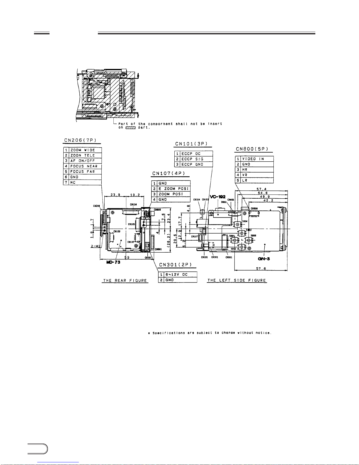
Dimensions (W/H/D)
Weight
Supplied accessory
410K/380K pixels
768 (H) ×494 (V)
More than 460 TV lines
More than 350 TV lines
1/3" Hyper HAD CCD
EVI-370 (NTSC)
EVI-370D (NTSC)
EVI-371 (PAL)
EVI-371D (PAL) EVI-370DG (NTSC) EVI-371DG (PAL)
470K/440K pixels
752 (H) ×582 (V)
More than 450 TV lines
More than 400 TV lines
410K/380K pixels
768 (H) ×494 (V)
More than 460 TV lines
More than 350 TV lines
470K/440K pixels
752 (H) ×582 (V)
More than 450 TV lines
More than 400 TV lines
—
(2 ×12 = ) 24×zoom
Approx. 48.8˚ (Wide end) to 4.3˚ (Tele end)
Approx. 37.6˚ (Wide end) to 3.2˚ (Tele end)
9 elements in 6 groups (Including 2 aspherical lenses)
10 mm (Wide end) : 800 mm (Tele end)
Y : VS 1.0 Vp-p sync negative
C : burst 0.286 Vp-p
VBS : 1.0 Vp-p composite
Y : VS 1.0 Vp-p sync negative
C : burst 0.300 Vp-p
VBS : 1.0 Vp-p composite
Y : VS 1.0 Vp-p sync negative
C : burst 0.286 Vp-p
VBS : 1.0 Vp-p composite
Y : VS 1.0 Vp-p sync negative
C : burst 0.300 Vp-p
VBS : 1.0 Vp-p composite
Internal Internal/External
—Video: 0 to 100 IRE
Sync : 40 IRE ±20% Video: 0 to 700 mV
Sync : 300 mV ±20%
7 lx F1.8 (More than 50 IRE)
More than 48 dB
ATW, one push hold, indoor preset, outdoor preset
27 steps
(1/60 sec. up to 1/10000 sec.)
28 steps
(1/50 sec. up to 1/10000 sec.)
27 steps
(1/60 sec. up to 1/10000 sec.)
28 steps
(1/50 sec. up to 1/10000 sec.)
Auto
0 to 50˚C/30 to 85%
–20 to +60˚C/20 to 90%
DC 6 to 12 V (Normal: 2.4 W, lens drive state: 3.2 W at 6 V DC)
DC 6 to 12 V (Normal: 2.6 W, lens drive state: 3.4 W at 6 V DC)
54 ×51 ×100 mm
220 g
225 g
2P, 3P, 4P, 6P, 7P, 10P harness
59 ×51 ×100 mm
230 g
2P, 3P, 4P, 5P, 6P, 7P, 9P, 10P harness
12x zoom, f = 5.4 to 64.8 mm, F = 1.8 to 2.7, wide macro, auto focus
(Inner focus system)
----------------------------------------------------------------------------------------------------------------------
----------------------------------------------------------------------------------------------------------------------
----------------------------------------------------------------------------------------------------------------------