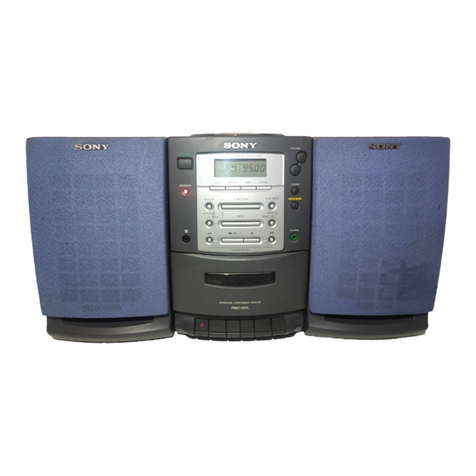
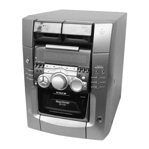
Sony PMC-R30L User manual

– 1 –
SERVICE MANUAL
AEP Model
UK Model
PMC-R30L
PERSONAL COMPONENT SYSTEM
CD player section
System
Compact disc digital audio system
Laser diode properties
Material: GaAlAs
Wave length: 780 nm
Emission duration: Continuous
Laser output: Less than 44.6 µW
(This output is the value measured at a distance of
about 200 mm from the objective lens surface on
the optical pick-up block with 7 mm aperture.)
Spindle speed
200 r/min (rpm) to 500 r/min (rpm) (CLV)
Number of channels
2
Frequency response
20 - 20,000 Hz +1/–2 dB
Wow and flutter
Below measurable limit
Radio section
Frequency range
FM 87.5 - 108 MHz
MW 531 - 1,602 kHz
LW 153 - 279 kHz
IF FM: 10.7 MHz
MW/LW: 450 kHz
Aerials
FM: External aerial terminal
MW/LW: External aerial terminal
– Continued on next page –
Cassette-corder section
Recording system
4-track 2 channel stereo
Fast winding time
Approx. 120 s (sec.) with Sony cassette C-60
Frequency response
TYPE I (normal): 70 - 10,000 Hz
General
Speaker
Full range: 10 cm dia.,
3 ohms, cone type (2)
Outputs
Headphones jack (stereo minijack)
For 16 - 68 ohms impedance headphones
Maximum power output
4.5 W + 4.5 W
Power requirements
For personal component system:
230 V AC, 50 Hz
For remote control:
3 V DC, 2 R6 (size AA) batteries
Power consumption
AC 23 W
CD Model Name Using Similar Mechanism PMC-107L
Section CD Mechanism Type KSM-213CDM
Optical Pick-up Name KSS-213C
TC Model Name Using Similar Mechanism PMC-107L
Section Tape Transport Mechanism Type MF-107
SPECIFICATIONS
MICROFILM
Ver 1.0 1999. 07

– 2 –
SAFETY-RELATED COMPONENT WARNING!!
COMPONENTS IDENTIFIED BY MARK !OR DOTTED LINE
WITH MARK !ON THE SCHEMATIC DIAGRAMS AND IN
THE PARTS LIST ARE CRITICAL TO SAFE OPERATION.
REPLACE THESE COMPONENTS WITH SONY PARTS WHOSE
PART NUMBERS APPEAR AS SHOWN IN THIS MANUAL OR
IN SUPPLEMENTS PUBLISHED BY SONY.
Dimensions (incl. projecting parts)
Player: Approx. 160 ×249 ×227 mm (w/h/d)
Speaker: Approx. 150 ×245 ×192 mm (w/h/d)
MassPlayer: Approx. 2.8 kg
Speaker: Approx. 1.2 kg
Supplied accessories
Remote control RMT-C107AD (1)
FM lead aerial (1)
MW/LW loop aerial (1)
Design and specifications are subject to change without
notice.
TABLE OF CONTENTS
1. SERVICING NOTES......................................................... 3
2. GENERAL
Playing a CD ........................................................................... 4
Listening to the radio............................................................... 4
Playing a tape .......................................................................... 5
Recording on a tape ................................................................. 5
3. DISASSEMBLY
3-1. Cabinet (Front) Assy ........................................................... 6
3-2. Cabinet (Upper) Assy .......................................................... 7
3-3. Power Board ........................................................................ 7
3-4. Main Board ......................................................................... 8
3-5. CD Board ............................................................................ 8
3-6. Optical Pick-up ................................................................... 9
3-7. Tape Mechanism Block ....................................................... 9
3-8. Control Board and Back Light Board ............................... 10
3-9. How to Apply the Belts ..................................................... 10
3-10. Head, Magnetic (HRP301)................................................ 11
3-11. Motor Assy (M301)........................................................... 11
4. MECHANICAL ADJUSTMENTS............................... 12
5. ELECTRICAL ADJUSTMENTS
Tape Section .......................................................................... 12
Tuner Section......................................................................... 13
CD Section ............................................................................ 14
6. DIAGRAMS
6-1. IC Pin Description............................................................. 15
6-2. Circuit Boards Location .................................................... 16
6-3. Block Diagram –CD Section–........................................... 17
6-4. Block Diagram –Main Section–........................................ 19
6-5. Printed Wiring Boards –CD Section– ............................... 21
6-6. Schematic Diagrams –CD Section– .................................. 23
6-7. Printed Wiring Boards –Control Section–......................... 25
6-8. Schematic Diagrams –Control Section– ........................... 27
6-9. Printed Wiring Boards –Main Section– ............................ 29
6-10. Schematic Diagram –Main Section (1/2)– ........................ 31
6-11. Schematic Diagram –Main Section (2/2)– ........................ 33
6-12. Printed Wiring Board –Power Supply Section– ................ 35
6-13. Schematic Diagram –Power Supply Section–................... 35
7. EXPLODED VIEWS
7-1. Cabinet (Rear) Section ...................................................... 40
7-2. Cabinet (Front) Section .....................................................41
7-3. Cabinet (Upper) Section.................................................... 42
7-4. Tape Mechanism Section-1 ............................................... 43
7-5. Tape Mechanism Section-2 ............................................... 44
7-6. Tape Mechanism Section-3 ............................................... 45
7-7. Tape Mechanism Section-4 ............................................... 46
7-8. Optical Pick-up Section .................................................... 47
7-9. Speaker Section ................................................................. 48
8. ELECTRICAL PARTS LIST......................................... 49

– 3 –
CAUTION
Use of controls or adjustments or performance of procedures
other than those specified herein may result in hazardous ra-
diation exposure.
NOTES ON HANDLING THE OPTICAL PICK-UP
BLOCK OR BASE UNIT
CHUCK PLATE JIG ON REPAIRING
On repairing CD section, playing a disc without the lid (CD), use
Chuck Plate Jig.
• Code number of Chuck Plate Jig: X-4918-255-1
The laser diode in the optical pick-up block may suffer electrostatic
breakdown because of the potential difference generated by the
charged electrostatic load, etc. on clothing and the human body.
During repair, pay attention to electrostatic breakdown and also use
the procedure in the printed matter which is included in the repair
parts.
The flexible board is easily damaged and should be handled with
care.
NOTES ON LASER DIODE EMISSION CHECK
The laser beam on this model is concentrated so as to be focused on
the disc reflective surface by the objective lens in the optical pick-
up block. Therefore, when checking the laser diode emission, ob-
serve from more than 30 cm away from the objective lens.
This Compact Disc player is classified as a
CLASS 1 LASER product.
The CLASS 1 LASER PRODUCT table is
location on the rear exterior.
SECTION 1
SERVICING NOTES
LASER DIODE AND FOCUS SEARCH OPERATION
CHECK
1. Open the CD lid.
2. Turn OPERATE switch on with to set the CD.
3. Turn on SW701 as following figure.
4. Press the ^(CD) button.
5. Confirm the laser diode emission while observing the objecting
lens. When there is no emission,Auto Power Control circuit or
Optical Pick-up is broken.
Objective lens moves up and down three times for focus search.
Push on SW701 in the
arrowed direction with
a screwdriver, etc.
SW701

– 4 –
SECTION 2
GENERAL This section is extracted
from instruction manual.

– 5 –

– 6 –
SECTION 3
DISASSEMBLY
• The equipment can be removed using the following procedure.
Note : Follow the disassembly procedure in the numerical order given.
3-1. CABINET (FRONT) ASSY
Set Cabinet (Front) assy Cabinet (Upper) assy
Power board
Tape mechanism block
Control board and Back Li
g
ht board
Main board
CD board Optical pick-up
How to apply the belts
Head, magnetic (HRP301)Motor assy (M301)
3
BVTP 3x14
1
BVTP 3x14
2
BVTP 3x1
4
4
CNP30
3
6
CNP301
0
wire
9
CNP702
7
CNP302
5
CNP306
8
CNP308
!¡
cabinet (front) assy

– 7 –
3-2. CABINET (UPPER) ASSY
3-3. POWER BOARD
2
BVTP 3x10
3
BVTP 3x10
5
cabinet (upper) assy
1
BVTP 3x10
4
CNP901
2
BVTP 4x16
3
POWER board
1
CNP902

– 8 –
3-4. MAIN BOARD
3-5. CD BOARD
2
BVTP 3x10
1
CNP704
3
MAIN board
1
CNP701
2
CNP703
3
connector
5
BVTP 3x10
7
CD board
6
sheet, plastic
4
BVTP 3x10

– 9 –
3-6. OPTICAL PICK-UP
3-7.TAPE MECHANISM BLOCK
3
optical pick-up
2
screws (2.6x16)
1
screws (2.6x16)
3
BVTP 3x10
2
BVTP 3x10
4
tape mechanism block
1
Open the cassette lid.

– 10 –
3-8. CONTROL BOARD AND BACK LIGHT BOARD
1
BVTP 3x10
6
BVTP 3x8
5
CNP801
7
BVTP 3x10
8
knob (SNOOZE)
9
BACK LIGHT board
2
BVTP 3x10
4
CONTROL board
3
CNP802
3-9. HOWTO APPLYTHE BELTS
2
belt
1
belt
motor assy (M301)
FW assy
idler assy, P
F

– 11 –
3-10. HEAD, MAGNETIC (HRP301)
3-11. MOTOR ASSY (M301)
2
screw
1
PTT 2x4
3
head, magnetic (HRP301)
1
spring
2
BVTT 2.6x5
4
PTT 2.6x6
holder, motor
5
motor assy (M301)
3
claw

– 12 –
phones jack (J302)
set
32
Ω
test tape
WS-48A
(3 kHz, 0 dB)
digital frequency
counter
TAPE SECTION 0 dB = 0.775 V
• Standard Output Level
Output terminal HP OUT
load impedance 32 Ω
output signal level 0.25 V (–10 dB)
• Test Tape
Type Signal Used for
WS-48A 3 kHz, 0 dB tape speed adjustment
Tape Speed Adjustment
Procedure:
Mode: playback
PRECAUTION
1. Clean the following parts with a denatured-alcohol-moistened
swab :
record/playback head pinch roller
erase head rubber belts
capstan idlers
2. Demagnetize the record/playback head with a head demagne-
tizer. (Do not bring the head magnetizer close to the erase head.)
3. Do not use a magnetized screwdriver for the adjustments.
4. After the adjustments, apply suitable locking compound to the
parts adjusted.
5. The adjustments should be performed with the rated power
supply voltage unless otherwise noted.
Torque Measurement
Mode Torque meter Meter reading
FWD CQ-102C 30 – 70 g • cm
(0.42 – 0.97 oz • inch)
FWD CQ-102C 1.5 – 5.5 g • cm
Back Tension (0.021 – 0.076 oz • inch)
FF CQ-201B more than 60 g • cm
(more than 0.83 oz • inch)
REW CQ-201B more than 60 g • cm
(more than 0.83 oz • inch)
Tape Tension Measurement
Mode Tension meter Meter Reading
FWD CQ-403A more than 100 g
(more than 3.53 oz)
SECTION 5
ELECTRICAL ADJUSTMENTS
SECTION 4
MECHANICAL ADJUSTMENTS
Adjust so that the value on the digital frequency counter is
3,000 Hz.
Specification Value:
Digital frequency counter
2,985 to 3,015 Hz
Adjust so that the frequency at the beginning and that at the end of
tape winding are between 2,955 to 3,045 Hz.
Adjustment Location:
TAPE SPEED
Adjustment

– 13 –
FM FREQUENCY COVERAGE
CHECK
Frequency Display 87.5 MHz 108 MHz
Reading on Digital voltmeter 1.8 ± 0.2 V 5.6 ± 0.2 V
Adjustment Part <confirmation> <confirmation>
FMTRACKING CHECK
Adjust for a maximum reading on level meter.
<confirmation> <confirmation>
87.5 MHz 108 MHz
MW FREQUENCY COVERAGE
ADJUSTMENT
Frequency Display 531 kHz 1,611 kHz
Reading on Digital voltmeter 0.9 ± 0.1 V 5.6 ± 0.2 V
Adjustment Part L5 CT4
MWTRACKING ADJUSTMENT
Adjust for a maximum reading on level meter.
L3 CT2
621 kHz 1,404 kHz
AM IF ADJUSTMENT
Adjust for a maximum reading on level meter.
CFT1
450 kHz
LW FREQUENCY COVERAGE
ADJUSTMENT
Frequency Display 153 kHz 279 kHz
Reading on Digital voltmeter 0.6 ± 0.1 V 5.3 ± 0.2 V
Adjustment Part CT3 <confirmation>
LW TRACKING ADJUSTMENT
Adjust for a maximum reading on level meter.
L4 CT1
162 kHz 261 kHz
Adjustment Location: MAIN board (See page 14.)
TUNER SECTION 0 dB = 1 µV
Precautions in Repairing
Note : As a tuner unit (TU1) is difficult to repair if faulty,
replace it with new one.
• FM Section
Setting:
BAND button: FM
22.5 kHz frequency
deviation by 400 Hz signal
output level : as low as possible
• MW/LW Section
Setting:
BAND button: MW or LW
30% amplitude
modulation by 400 Hz signal
output level : as low as possible
• Connecting Level Meter (FM, MW and LW)
• Connecting Digital Voltmeter (FM, MW and LW)
• Repeat the procedures in each adjustment several times, and the
frequency coverage and tracking adjustments should be finally
done by the trimmer capacitors.
FM terminal
(CNP2)
FM RF signal
generator
0.01
µ
F
set
Put the lead-wire
antenna close to
the supplied
MW/LW loop aerial.
AM RF signal
generator
phones jack (J302)
set
32
Ω
level meter
(range: 0.5-5 V ac
)
digital
voltmeter
tuner board
TP (VT)

– 14 –
C706
C711
C712
CNP701
C723
C709 R704
1
16
R701
R706
R721
R720
R725
R726
R715
R717
R740
JW705
JW703
JW713
152
13
14
26 27
39 40
C705
C724
C717
C721
C715
C707
C737
C738
IC701
TP (RF)
– CD board (conduction side) –
Adjustment Location:
CD SECTION
CD section adjustments are done automatically in this set.
In case of operation check, confirm that focus bias.
FOCUS BIAS CHECK
1. Connect the oscilloscope between IC701 pin #£ (TP RF) and
GND on CD board.
2. Set the Test DiscYEDS-18 (CD). (Part No. : 3-702-101-01)
3. Press the ^(CD) button.
4. Confirm that the oscilloscope waveform is as shown in the
figure below. (eye pattern)
A good eye pattern means that the diamond shape ( ) in the
center of the waveform can be clearly distinguished.
• RF signal reference waveform (eye pattern)
π
Test Point:
RF level :
1.2
±
0.1 Vp-p
VOLT/DIV : 200 mV (10 : 1 probe in use)
TIME/DIV : 500 nS
When observing the eye pattern, set the oscilloscope for AC range
and raise vertical sensitivity.
L4
CT1
LW
TRACKING
ADJUSTMENT
CFT1
AM IF
ADJUSTMENT
IC1
TU1
TP (VT) (conductor side)
CNP2
CT4
L5
MW
FREQUENCY
COVERAGE
ADJUSTMENT
CT3
LW
FREQUENCY
COVERAGE
ADJUSTMENT
L3
CT2
MW
TRACKING
ADJUSTMENT
– MAIN board (component side) –

– 15 – – 16 –
6-2. CIRCUIT BOARDS LOCATION
Pin No. Pin Name I/O Pin Description
77 – 88 SEG20 – 31 O LCD segment signal output terminal
89 VDD — Power supply (+ 5V)
90 NC — Connected to VDD.
91 VSS — Ground
92 TX O Crystal connection for clock oscillation. (32.768 kHz)
93 TEX I Crystal connection for clock oscillation. (32.768 kHz)
94 – 98 SEG32 – 36 O LCD segment signal output terminal
99 REC I Tape REC detection signal input (from SW301)
100 PLAY I Tape PLAY detection signal input (from S302)
MAIN board
CD board
CD MOTOR board
POWER board
HEADPHONE board
REC SW board
KEY board
CONTROL board
BACK LIGHT board
6-1. IC PIN DESCRIPTION
• IC801 CXP83232A-015Q (SYSTEM CONTROL)
Pin No. Pin Name I/O Pin Description
1 REG I AC check input
2 C-SCOR I CD-SCOR input
3 RMC I SIRCS receiver input
4, 5 NC — Not used.
6 C-SENS I CD SENS-1 input
7 C-SENS2 I CD SENS-2 input
8 RDS-CLK O Tuner demodulator clock output
9 RDS-DATA O Tuner demodulator data output
10 C-XRST O CD system reset output
11 C-SQCK O Clock output for CD SUB-Q.
12 C-SQSO I CD SUB-Q input
13 A-MUTE O Mute signal output for audio.
14 R-ST I Stereo detection input
15 R-COUNT I Tuner PLL IC count input
16 R-DATA O Tuner PLL IC data output
17 R-CLK O Tuner PLL IC clock output
18 R-CE O Tuner PLL IC chip enable output
19 V-CE O Electrical volume chip enable output
20 V-DAT O Volume data output
21 V-CLK O Volume clock output
22 C-CLK O Clock output for CD-DSP command.
23 C-XLAT O CD-DSP command latch output
24 C-DATA O CD-DSP command data output
25 PA-CON O Power on/off control output
26 REG-CON O Regulator on/off control output. LED (STANDBY) control signal output.
27 C-MUTE O Mute signal output for CD.
28 BACKLIGHT-ON O Not used.
29 RDS-IND O Not used.
30 – 32 KEY1 – 3 I Key return signal input
33 VER I Mode setting terminal
34 C-DOOR I CD lid open/close detection input
35 NC — Not used.
36 9/10K I Not used.
37 SHIFT-CLK O Shift clock on/off output
38 RST I Reset signal input
39 EXTAL I Clock oscillation input (8 MHz)
40 XTAL O Clock oscillation output (8 MHz)
41 VSS — Ground (for A/D converter)
42, 43 NC — Not used.
44 AVREF I Reference voltage input (for A/D convereter)
45 AVSS — Ground (for A/D converter)
46 VL O LCD bias resistor current control terminal (Cut off at standby)
47 – 49 VLC3 – 1 — LCD bias power supply terminal
50 – 53 COM0 – 3 O LCD common signal output terminal
54 – 73 SEG0 – 19 O LCD segment signal output terminal
74 RADIO O Regulator on/off control output for radio block.
75 TAPE O Regulator on/off control output for tape block.
76 CD O Regulator on/off control output for CD block.
SECTION 6
DIAGRAMS

PMC-R30L
6-3. BLOCK DIAGRAM — CD SECTION —
– 17 – – 18 –
A5CNP701
CNB703
7
6
4
10
12
3
8
14
15
13
16
C
B
E
F
D
LD
PD
LD ON
SWITCH
Q701
LASER
DIODE
CONTROL
PD1
PD2
LD
PD
E
F
VC
RF AMP
SERIAL/
PARALLEL
CONVERTER
DECODER
COMMAND
FE AMP
VREF
TTL
IIL XRST
CLK
XLT
DATA
SENS2
SENS1
C. OUT
FOK
RF O
IIL
TTL
42
41
51
13
36
39
37
23
20
21
22
26
25
24
33
27
38
RF AMP & SYSTEM SERVO PROCESSOR
IC701
TRACKING
PHASE FOCUS
PHASE
6 16
TAO
FEO
SLO
19
17
18
TRACKING
COIL
DRIVE
25
7
FOCUS
COIL
DRIVE
TIN
FIN
3
SLED
MOTOR
DRIVE
SLIN
15
SPINDLE
MOTOR
DRIVE
SPI
MUTE
T+
T–
26
27
F+
F–
2
1
SL+
SL–
12
11
SP+
SP–
TRACKING
COIL
FOCUS
COIL
OPTICAL PICK-UP
BLOCK
(KSS-213C)
M
M
M702
SLED
MOTOR
M701
SPINDLE
MOTOR
SLED/SPINDLE
MOTOR DRIVE
TRACKING/FOCUS
COIL DRIVE
IC702
S701
(LIMIT)
RF
FOK
CNIN
SEIN
DATO
XLTO
CLKO
XRST
SERVO
AUT
SEQ.
D/A
INTERFACE
SUB CODE
PROCESSOR
EFM DEMODULATOR
DIGITAL
CLV CPU INTERFACE
MDP
XLON
SENS
SQSO
SCOR
SPOA
SQCK
DATA
XLAT
CLOK
SYSM
XTAI
XTAO
SERIAL
INTERFACE
DIGITAL
FILTER
&
D/A
CONVERTER
AOUT1
LOUT1
AOUT2
LOUT2
PWM
AMP
PWM
AMP
CD L-CH
R-CH
MAIN
SECTION
1
35
18
11
10
12
13
14
79
21 15 17 6 5 574 7 8 9 62 70•71
65
67
76
74
DIGITAL SIGNAL PROCESSOR, D/A CONVERTER
IC703
10
74
34
67 12 11 24 23 22 272
X701
16.9344MHz
XRST
SENS2
SENS1
SQSO
SQCK
SCOR
DATA
XLAT
CLK
MUTE
C-DOOR CD
RADIO
76
CD
SYSTEM CONTROL
IC801 (1/2)
RADIO ON
SWITCH
Q306
CD ON
SWITCH
Q302,307
COM
5V
RA5V COM
5V
CD5V
SW701
(CD DOOR)
04
• Signal path
: CD
R-ch : same as L-ch.
4
3
6
5
2
1
CNP705
1
2
CD BOARD
MAIN BOARD
(1/2)
CONTROL BOARD (1/2)
3
CNP704
1
9CNP303
11
9CNP805
11
CNP806
11
1098536712
4
CNP702
1
23479651110
8
(Page 19)

6-4. BLOCK DIAGRAM — MAIN SECTION —
PMC-R30L
– 19 – – 20 –
M
5
4
21
6
24
99
100
18 17 16 15
40 39 37
14
50–53
15
75
17 13 12 20 19 18
21 20 19 13
26
21
20 31 24 11
5
5
23
22
PBIN1
REC1
P/R
VREFVREF
RAIN1
TAPE
CDIN1
CD L-CH
ALC AMP
SW301
REC
PB -1
-2
CONTROL SEL
OUT1
PRE-AMP
IC301
R-CH
R-CH
L-CH
HRP301
RECORD/PLAYBACK
HEAD
1
CD
SECTION
S302
(MD PLAY)
S301
(MD POWER)
PLAY
COM0
REC
COM3
54–73,77–88,94–98
92•93 30–32
SEG0
SEG36
R-CE
R-CLK
R-DATA
R-COUNT
LCD801
SURROUND TONE VOL
CONTROL
PORT2
PORT1
CLK
DATA
BC
LATCH
VOLUME/SOUND CONTROL
IC302 POWER AMP
IC303
Q304 SP301
SPEAKER
(L-CH)
R-CH R-CH
J302
PHONES
V-CE
A-MUTE
25
PA-CON
38
29
RST
RDS IND
V-DATA
V-CLK
TAPE
X802
32.768kHz
X801
8MHz
CLOCK
SHIFT
Q802
CLOCK
SHIFT
Q801
R-ST
KEY1
KEY3
3
IR
RECEIVER
IC802
RMC
8
CLK
9
DATA
SHIFT-CLK
EXTAL
XTAL
TEX
TX
1
REG
REG
CON
RESET
IC804
REG
Q309,310
LED DRIVE
Q803
REG
Q308
REG
IC803
T901
POWER
TRANSFORMER
SYSTEM CONTROL
IC801 (2/2)
S801–803,
807
S808–823,
825,826 S805,806
RECT
D901–904
SWITCH
Q807
D905
AC IN
MUTE
CONTROL
Q305,311, 313
STBY
OUT2
VC
IN2
+8V
M301
CAPSTAN /REEL
MOTOR
RA 5V
+5V
VREF
VREF
BIAS
OSC
Q303
REC/PB
SW
Q301, 312
REC
PB
T301
REC
BIAS
Signal path
: FM
: MW
: PB
: REC
: CD
R-ch : same as L-ch.
RDS
VDD
5V
S824
RESET
8V
D806
R•D•S
COM5V
VDD5V
REG
Q314
CD6V
VCC
4
11
567
CE
CK
DA
CD
CE
CK
DA
CD
MW
10 LW
21 17 16 1 2 8
13
13 18
14 171920
2124
17
8
5
22
4 6
16 15 11
12
10
2
PD1
FM IN
AM IN
XOUT
XIN
IF IN
MO/ST
FM
X1
75kHz
9
IF REG
1514
AM
OSC
FM
OSC
AM
MIX
FM
MIX
AM IN IF
BUFFER
MO/ST
BAND
ST-IND
AM
DET
7FM
DET
AF
BUFFER FM
MPX MUTE R-CH
QUAD
R
L
CF3CF2CF1
CFT1
Q9
LW
SWITCH
Q5
LW
SWITCH
Q4
LPF
Q16
VT
Q17
MW/LW
SWITCH
Q2,3
L3, 4
(MW/LW ANT)
CT1
CT2
AMP
Q1
8V
D302
Q7
Q6
D3
RADIO 5V
L5
CT3 CT4
FM/MW/LW FRONT-END, IF DET,
FM STEREO DEMODULATOR
IC1
PLL
IC2
Q15
Q20
Q8
Q11 Q14
OSC
CNP2
MW/LW
FM
CNP1
POWER
CONTROL
Q10,22
AMP
Q18
AM HI-CUT
Q13
TU8V 8V
POWER
CONTROL
Q21
RDS5V RA5V
L15
B-MUTE
ANT VT OSC OUT
IF OUT
TU1
12
RDATA
RDATA
16
RCLK
RCLK
4
MUX
13
XI
14
XO
X2
4.332MHz
RDS
MODULATOR
IC3
CE
CK
DA
CD
RDATA
RCLK
LED DRIVE
Q805
D804
OPERATE
CNP304
5
CNP301
4
3
2
HE301
ERASE HEAD
4
3
2
CNP302
1
2
4
3
CNP311
1
2
4
3
CNP306
6
5
4
2
1
6
5
4
33
2
1
3
8 10 4 14 13 12 15 19 22 18
23
16
2 15 6 7 17
REC SW
BOARD POWER BOARD
CONTROL BOARD (2/2) KEY
BOARD
BACK LIGHT
BOARD
HEADPHONE BOARD
MAIN BOARD (2/2)
CNP303
3
8 10 4 14 13 12 15 19 22 182 15 6 7 17 CNP805
2
3
23
16
CNP805
2
CNP803
CNP804
2
5
3
4
CNP307
J301
SPEAKER
2
5
3
4
CNP308
CNP
303
CNP
305
2
3
CNP901
2
3-5 CNP802
1
3-5
CNP801 1
04
CFT1
AM IF
CT1,L4
LW
TRACKING
CT2,L3
MW
TRACKING
CT3
LW
FREQUENCY
COVERAGE
CT4,L5
MW
FREQUENCY
COVERAGE
(Page 18)

1
A
B
C
D
E
F
G
234567891011121314
R703
R705
C702
C706
C711
C712
L704
CNP701
C723
Q701
C709
C701
C722
C727
R724
R756
R723
R702
R704
1
16
R701
R706
R710
R729
R721
R720
R752
R757
R738
R730
R734
R727
R725
R758
R728
R726
R715
R717
R719
R740
R744
R745
R746
R743
R759 R733
R732R713
C760
R742
R741
CNP702
R755
R735
CNP703
R748
R731
R736
R754
C708
C714
C704
C710
R747
C749
C703 JW732
JW739
JW726
JW725
JW721
JW740
JW714
JW706
JW707 JW708
JW704
JW736
JW723
JW735
JW734
JW731
JW712
JW702
JW705
JW703
JW713
JW738
JW701
JW729
JW718
JW720
JW719
JW717
JW722
JW716
JW715
JW711
JW710
JW727
JW728
JW737
JW724
JW730
JW733
1
152
13
14
26 27
39 40
14
15 28
R714
R722
R716
C716
C705
C729
C724
C719
C717
C721
C715
C730
C731
C739
C740
C713
R718
R711
R737
R707
R709
R712
C707
CD BOARD
1
MAIN BOARD
CNP304
SW701
(CD DOOR)
2
CONTROL BOARD
CNP806
OPTICAL PICK-UP
UNIT
KSS-213C
04
C770
C732
C748
C718
C734
C725
C744
IC702
C753
C756
C776
C769
C765
C720
C743
C766
C742
C737
C738
C759
C763
C767
C764
C733
C757
C778
C777
C758
C751
C774
IC703
IC701
C772
C754
C782
R751
X701
C752
C745
C741
C726
C779
C768
C728
R753 C761
R739
R750
R749
C762
C755
C750
C773
L701
L705
FB701
FB702
L703
C775
C783
L702
CNP705
CNP704
1-674-301- 11
16
1
2
1
11
1
7
CD MOTOR BOARD
1-658-023-
S701
(LIMIT)
M701
(SPINDLE)
CNP707
1BLK
BLK
BLK
BLK
BLK
WHT
6
31
(31)
MM702
(SLED)
M
1
80
61 60
41
40
21
20
TP(RF)
PMC-R30L
– 21 – – 22 –
6-5. PRINTEDWIRING BOARDS — CD SECTION — • Refer to page 16 for Circuit Boards Location.
Common note on Printed Wiring Boards:
•X: parts extracted from the component side.
•¢: internal component.
•b: Pattern from the side which enables seeing.
IC701 E-6
IC702 B-7
IC703 D-4
Q701 F-4
• Semiconductor
Location
Ref. No. Location
(Page 30)
(Page 25)
Common note on Schematic Diagram:
• All capacitors are in µF unless otherwise noted. pF: µµF
50 WV or less are not indicated except for electrolytics
and tantalums.
• All resistors are in Ωand 1/4W or less unless otherwise
specified.
•¢: internal component.
•C: panel designation.
•U: B+ Line.
• Voltage is dc with respect to ground under no-signal
(detuned) condition.
• Waveforms are dc with respect to ground in playback
mode.
no mark : FM or CD
( ) : MW
<>:LW
∗: Impossible to measure
• Voltages are takenwithaVOM(Input impedance 10MΩ).
Voltage variations may be noted due to normal produc-
tion tolerances.
• Waveforms are taken with a oscilloscope.
Voltage variations may be noted due to normal produc-
tion tolerances.
• Circled numbers refer to waveforms.
• Signal path.
F: FM
f: MW
E: PB
a: REC
J: CD
Note: The components identified by mark !or dotted line
with mark !are critical for safety.
Replace only with part number specified.

PMC-R30L
– 23 –
6-6. SCHEMATIC DIAGRAMS — CD SECTION — • Refer to page 36 for IC Block Diagrams.
– 24 –
Approx. 100mVp-p
IC701 $¶ (TEI)
•Waveforms (MODE:PLAY)
1
2
3
4
5
2.5V
1.2±0.1Vp-p
Approx. 200mVp-p
IC701 1(FEO)
2.5V
IC703 @¡ (MDP)
2Vp-p
7.6µsec
16.9344MHz
IC703 &¡ (XTAO)
2.2Vp-p
IC701 #£ (RFO)
(Page 34) (Page 27)

1
A
B
C
D
E
F
G
H
I
234567891011121314
KEY BOARD
BACK LIGHT BOARD
CONTROL BOARD
2 3
CD BOARD
CNP702 MAIN BOARD
CNP303
04
S809
STANDBY
1-674-300- 11
1-674-301- 11
1-674-303- 11
S805
SNOOZE
S825
SOUND
S817
DSPL
ENT MEM
S822 S808
S814
CNP801
SLEEP
S816
PLAY MODE•
MONO/ST ISS
S815
PRESET + S813
BAND S823
PRESET –
S818 S819 S820 S821
S810
SUMMER S811
CLOCK
R•D•S
S812
TIMER
S826
FUNCTION
R820
R821
D806
R822
R826
R824
R823
R838
JW805
R819
R833
R827
R828
R829
R830
R831
R834
R801
R835
R806
R818
R863
R847
R848
R849
R850
R816
R810
R809
R808
R846
R811
R845
R844
R804
R880
R872
R873
R805
R832
R840
R839
R874
R865
R875
R864
R836
R860
R843
R837
R842
R841
R862
R858
R857
R856
R859
R855
R854
R881
R861
R812
R813
R815
R814 R869
R876
R866
R877
R868
R878
IC803
R817
R867
CNP802
R853
R851
R852
C820
C821 C823
C813
C829
C831
C830
C810
C832
JW824
JW842
JW838 JW845
JW835
JW822
JW816
JW826
JW841
JW823
JW820
JW801
D801 JW839
JW821
JW825
JW810
JW844
L801
D802
JW836
JW837
JW813
JW834
JW833
JW843
JW815
JW804
JW846
JW808
JW2
JW807JW831
C802
Q801
Q802
Q805
Q803
C809
X801
C806
C805
C801
C804
C814
CNP805
CNP806
C811
IC802
C822
X802
C835
L804
C824
C828
C838
C815
C816
C817
C818
C825
C833
C826
C808
C803
R807
C836
C837
C807
C827
R870 R871
IC801
R825
S802
S803
R879
JW806
JW803
JW802
JW840
R883
R882
R803
R802
S807
OPERATE
CNP804
CNP803
D805
Q807
D804
D803
LCD801
LIQUID CRYSTAL
DISPLAY PANEL
S801
MEGA BASS
STANDBY
IC804
S806
SNOOZE
12
+TUNING•TIME SET –
AMS/SEARCH
1
5
^"=~|
"=~|
1
1
22
23
2
1
10
3
–
+
1
1
11 1
5
3
3
5
12
VOLUME
1
81 80
5150
31 30
100
141
PMC-R30L
– 25 – – 26 –
6-7. PRINTEDWIRING BOARDS — CONTROL SECTION — • Refer to page 16 for Circuit Boards Location.
D801 F-2
D802 G-6
D803 G-6
D804 F-8
D805 F-2
D806 D-11
IC801 E-4
IC802 H-1
IC803 F-6
IC804 E-2
Q801 E-6
Q802 E-6
Q805 F-7
Q807 F-2
• Semiconductor
Location
Ref. No. Location
(Page 21) (Page 30)
Other manuals for PMC-R30L
1
Table of contents
Other Sony Speakers System manuals

Sony
Sony SA-VS150H User manual

Sony
Sony SS-CN5000 User manual

Sony
Sony NSA-PE1 User manual

Sony
Sony HT-CT800 User manual

Sony
Sony SRS-A5 Operating Manual... User manual

Sony
Sony WH-L600 User manual

Sony
Sony HT-S400 User guide

Sony
Sony SRS-T70 User manual

Sony
Sony SS-V130 User manual

Sony
Sony SRS-A57 User manual

Sony
Sony SRS-PC15 User manual

Sony
Sony HT-A3000 User guide

Sony
Sony SS-FCR4000 Installation instructions manual

Sony
Sony SS-GN800 User manual

Sony
Sony HT-NT3 User guide

Sony
Sony SAVA-7 User manual

Sony
Sony SS-X70ED User manual

Sony
Sony HT-S2000 User manual

Sony
Sony SRS-PC51 User manual

Sony
Sony SS-DP1000DW User manual