Continuous
RMS
power
output
23W
+
23W
(4
ohms
at
IkHz,
5%
THD)
Inputs
MDIN:
Sensitivity
450
mV,
impedance
47
kilohms
Outputs
MD
OUT
‘Senitivity
250
mV,
1kQ
PHONES
(stereo
phone
jack)
:
accept
headphones
of
8
ohms
or
more.
Supplied
accessories
AM
loop
antenna
(1)
Remote
(1)
Sony
SUM-3
(NS)
batteries
(2)
FM
lead
antenna
(1)
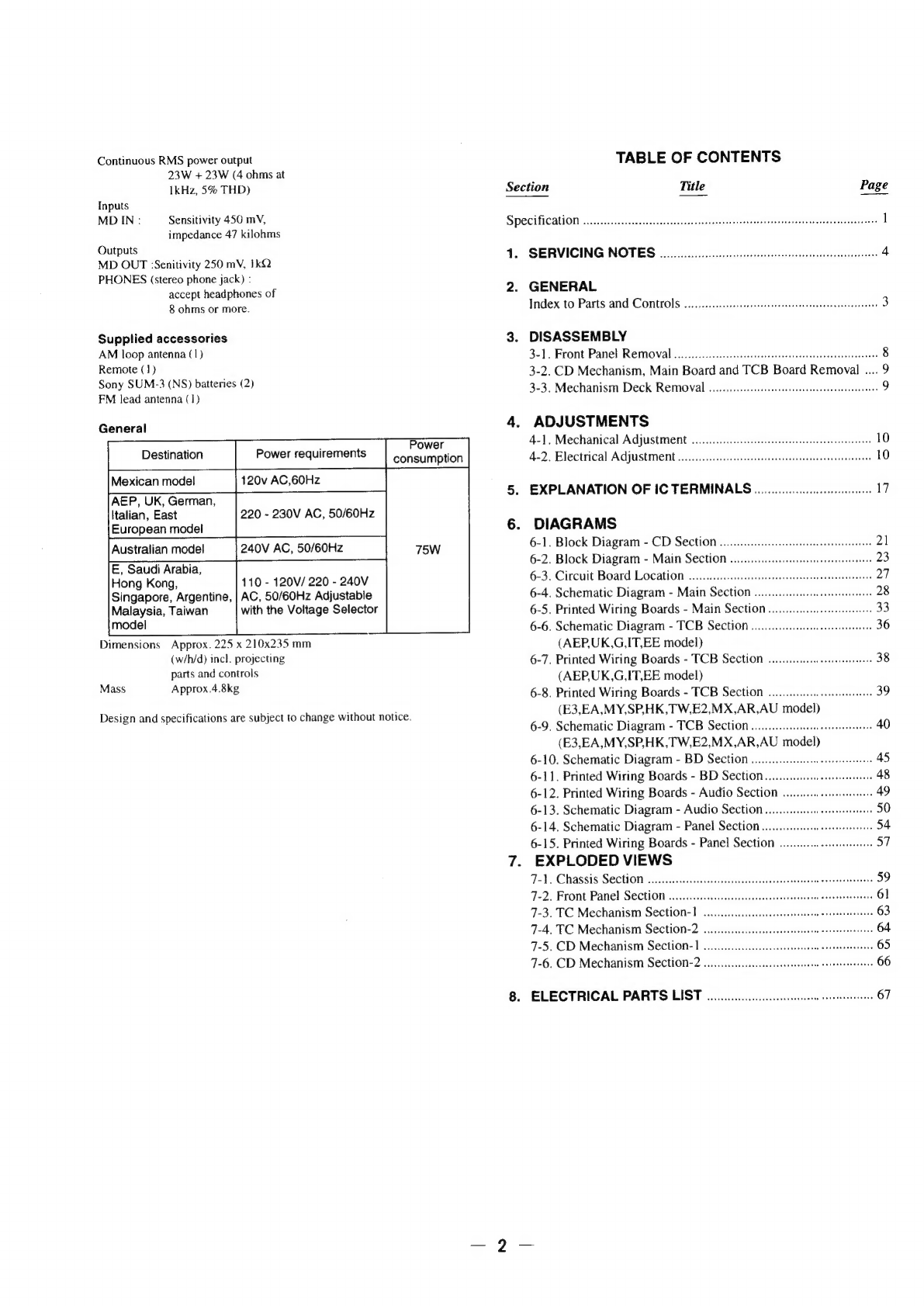
General
Destination
Power
requirements
Mexican
model
AEP,
UK,
German,
Italian,
East
European
model
E,
Saudi
Arabia,
Hong
Kong,
Singapore,
Argentine,
Malaysia,
Taiwan
model
Dimensions
Approx.
225
x
210x235
mm
(w/h/d)
incl.
projecting
parts
and
controls
Mass
Approx.4.8kg
110
-
120V/
220
-
240V
AC,
50/60Hz
Adjustable
with
the
Voltage
Selector
Design
and
specifications
are
subject
to
change
without
notice.
Power
consumption
120v
AC,60Hz
220
-
230V
AC,
50/60Hz
Australian
model
240V
AC,
50/60Hz
75W
TABLE
OF
CONTENTS
Section
Title
Page
Specification
oo...
cesses
sesseseeceneneasseneanerarererevenseensneasnanssaescess
1
1.
SERVICING
NOTES
00
cerecneeneerteeteerntees
4
2.
GENERAL
Index
to
Parts
and
Controls
.......cc.cccccceeeseseeecesnseeseesteeeeeneeenseeee
3
3.
DISASSEMBLY
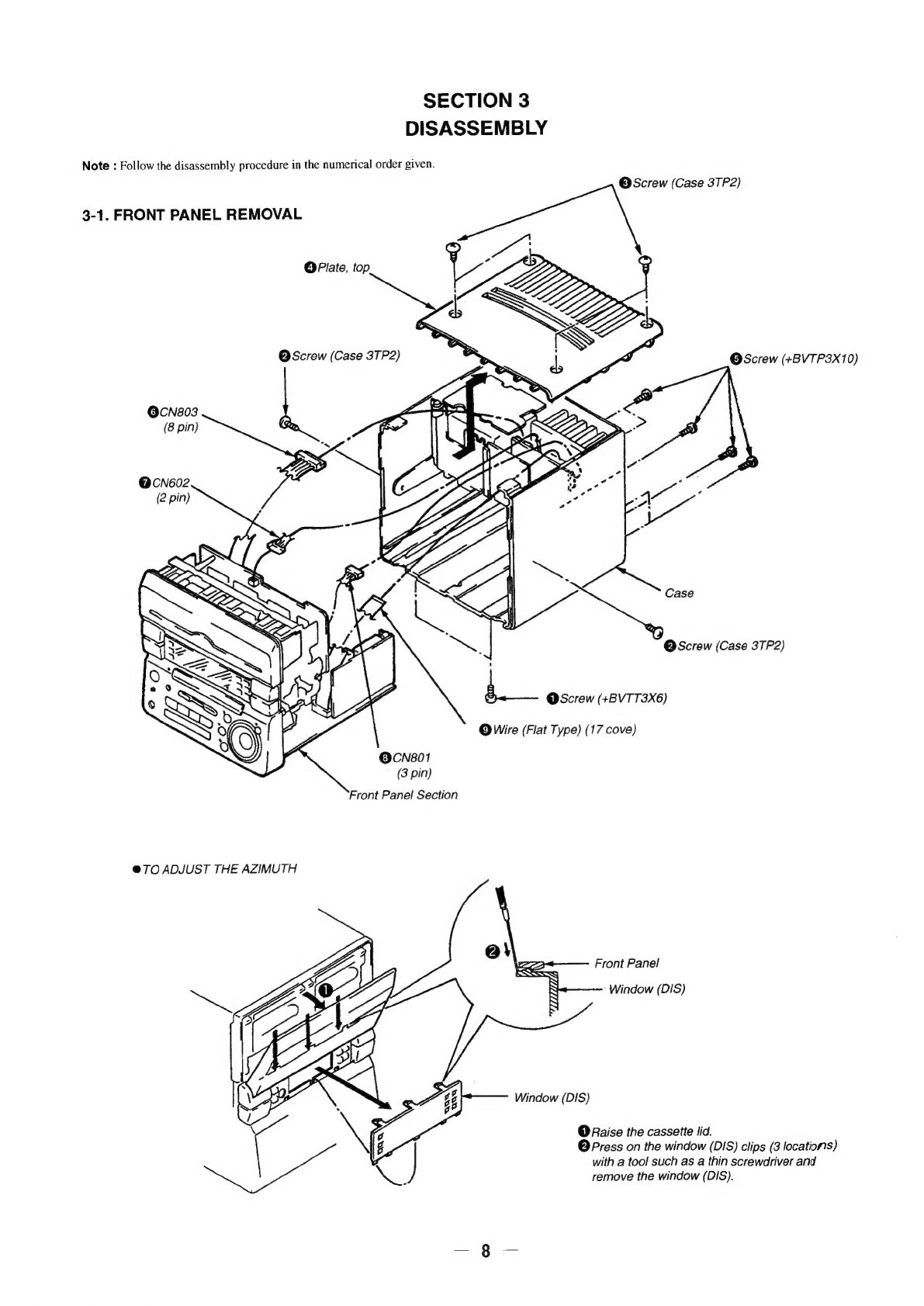
3-1.
Front
Panel
Removal
.....0....cccceccsccccerecrseetsceeesteeseternereeenees
8
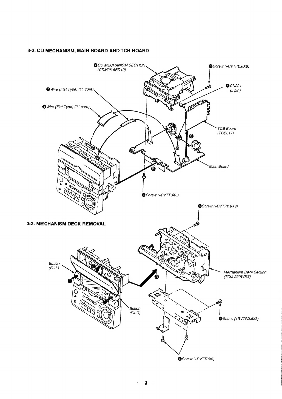
3-2.
CD
Mechanism,
Main
Board
and
TCB
Board
Removal
....
9
3-3.
Mechanism
Deck
Removal
.........::cccceescessseseteeeesseerseenaees
9
4.
ADJUSTMENTS
4-1.
Mechanical
Adjustment
.........ccccccceccesereserseeeeeeseeeenens
10
4-2.
Electrical
Adjustment
........cccccccssse
ese
cereeerseertceteessanes
10
5.
EXPLANATION
OF
IC
TERMINALS
.........00000
ee
17
6.
DIAGRAMS
8.
6-1.
Block
Diagram
-
CD
Section.......
6-2.
Block
Diagram
-
Main
Section
...
“
6-3.
Circuit
Board
Location
occ
ee
creteee
cn
eteeseeenenees
27
6-4.
Schematic
Diagram
-
Main
Section
........ccccces
eres
28
6-5.
Printed
Wiring
Boards
-
Main
Section
anos
6-6.
Schematic
Diagram
-
TCB
Section
.......c
cece
erences
36
(AEP,UK,G,IT,EE
model)
6-7.
Printed
Wiring
Boards
-
TCB
Section
.....ccccee
cesses
38
(AEP,UK,G,IT,EE
model)
6-8.
Printed
Wiring
Boards
-
TCB
Section
......cc:c
cece
39
(E3,EA,MY,SP,HK,TW,E2,MX,AR,AU
model)
6-9.
Schematic
Diagram
-
TCB
Section
wo...
ceeeeeetetees
40
(E3,EA,MY,SP,HK,TW,E2,MX,AR,AU
model)
6-10.
Schematic
Diagram
-
BD
Section
vo...
cece
eee
tenes
45
6-11.
Printed
Wiring
Boards
-
BD
Section
.......cccce
eesti
48
6-12.
Printed
Wiring
Boards
-
Audio
Section
........04
reece
49
6-13.
Schematic
Diagram
-
Audio
Section
6-14.
Schematic
Diagram
-
Panel
Section
6-15.
Printed
Wiring
Boards
-
Panel
Section
.........0
esse
37
EXPLODED
VIEWS
Fale
Chassis
Section
2:...ccccsiocc
tsvesscaes
ccevsens
veveegsoveonsaale
Soteriacnesens
7-2.
Front
Panel
Section
.......cccc
ce
cceeeseceseeneensesaaes
eee
7-3.
TC
Mechanism
Section-]
oo...
ceeeeeetsteeee
cree
7-4.
TC
Mechanism
Section-2
...
7-5.
CD
Mechanism
Section-1
...
7-6.
CD
Mechanism
Section-2
oo...
ccccceneseee
eee
ceteetteetnees
ELECTRICAL
PARTS
LIST
ooo.
ete
67