Sony HCD-CP33 User manual

HCD-CP33
US Model
Canadian Model
AEP Model
UK Model
E Model
Australian Model
Tourist Model
SERVICE MANUAL
MICRO Hi-Fi COMPONENT SYSTEM
— Continued on next page —
SPECIFICATIONS
Dolby noise reduction manufactured under license
from Dolby Laboratories Licensing Corporation.
“DOLBY” and the double-D symbol aare trade-
marks of Dolby Laboratories Licensing Corporation.
HCD-CP33 is the Amplifier, MD player,
CD player, Tape Deck andTuner section
in CMT-CP33MD.
Note
CD block, tape deck block and
tuner pack are supplied with
the assembled block.
Amplifier section
For the U.S. model
AUDIO POWER SPECIFICATIONS
POWER OUTPUTAND TOTAL HARMONIC
DISTORTION:
With 6-Ωloads, both channels driven, from
70 – 20,000 Hz; rated 18 W per channel
minimum RMS power, with no more than 0.9%
total harmonic distortion from 250 mW to
rated output.
North American model:
Continuous RMS power output (reference):
35 + 35 W
(6 Ωat 1 kHz, 10% THD)
Total harmonic distortion: less than 0.07%
(6 Ωat 1 kHz, 18 W)
European model:
DIN power output (Rated):30 + 30 W
(6 Ωat 1 kHz, DIN, 230 V)
Continuous RMS power output (Reference):
35 + 35 W
(6 Ωat 1 kHz,10% THD, 230V)
Music power output (Reference):
85 + 85 W
Other models:
The following measured at 230V AC, 60 Hz
DIN power output (rated): 28 + 28 W
(6 Ωat 1 kHz, DIN)
Continuous RMS power output (reference):
30 + 30 W
(6 Ωat 1 kHz, 10% THD)
The following measured at 220V AC, 60 Hz
DIN power output (rated): 24 + 24 W
(6 Ωat 1 kHz, DIN)
Continuous RMS power output (reference):
25 + 25 W
(6 Ωat 1 kHz, 10% THD)
Inputs
VIDEO IN (phono jacks): voltage 250 mV, impedance 47 kΩ
Outputs
LINE OUT (phono jack): voltage 250 mV, impedance 1 kΩ
PHONES (stereo minijack):
accepts headphones of 8 Ωormore.
SPEAKER: accepts impedance of 6 to16 Ω
CD player section
System Compact disc and digital audio
system
Laser Semiconductor laser (l=780 nm)
Emission duration: continuous
Laser output Max. 44.6 µW*
*This output is the value measured
at a distance of 200 mm from the
objective lens surface on the
Optical Pick-up Block with 7 mm
aperture.
Frequency response 2 Hz – 20 kHz
Model Name Using Similar Mechanism HCD-CP11
CD Mechanism Type CDM55-K5BD41
Model Name Using Similar Mechanism HCD-MDX10
Mechanism Type MDM-5A
Optical Pick-up Type KMS-260A/K1NP
Model Name Using Similar Mechanism HCD-CP11
Tape Transport Mechanism Type TCB-020
CD
Section
MD
Section
Tape deck
Section
Ver 1.2 2003. 05
Sony Corporation
Home Audio Company
Published by Sony Engineering Corporation
9-929-276-13
2003E16-1
© 2003.05

2
MD deck section
System MiniDisc digital audio system
Laser Semiconductor laser (l=780 nm)
Emission duration: continuous
Laser output Max. 44.6 µW*
*This output is the value measured
at a distance of 200 mm from the
objective lens surface on the
Optical Pick-up Block with 7 mm
aperture.
Sampling frequency 44.1 kHz
Frequency response 5 Hz –20 kHz
Tape deck section
Recording system 4-track 2-channel stereo
Frequency response (DOLBY NR OFF)
40 –13,000 Hz (±3 dB),
using Sony TYPE I cassettes
40 –14,000 Hz (±3 dB),
using Sony TYPE II cassettes
Tuner section
FM stereo, FM/AM superheterodyne tuner
FM tuner section
Tuning range
North American model: 87.5 –108.0 MHz
(100 kHz step)
Tourist model: 7 6.0 –108.0 MHz
(50 kHz step)
Other models: 87.5 –108.0 MHz
(50 kHz step)
Antenna FM lead antenna
Antenna terminals 75 Ωunbalanced
Intermediate frequency 10.7 MHz
AM tuner section
Tuning range
Pan-American model: 530 –1,710 kHz
(with the interval set at 10 kHz)
531 –1,710 kHz
(with the interval set at 9 kHz)
European model: 5 31 –1,602 kHz
(with the interval set at 9 kHz)
Other models: 531 –1,602 kHz
(with the interval set at 9 kHz)
530 –1,710 kHz
(with the interval set at 10 kHz)
Antenna AM loop antenna
External antenna terminals
Intermediate frequency 450 kHz
GENARAL
Power requirements
North American model: 120 V AC, 60 Hz
European model: 230 V AC, 50/60 Hz
Australian and Thai models:
220 –240 V AC, 50/60 Hz
Other models: 110 –120 V or 220 –240 V AC,
50/60 Hz
Adjustable with voltage selector
Power consumption 75 W
Dimensions (w/h/d) incl. projecting parts and controls
Amplifier/Tuner/Tape/MD/CD section:
Approx. 190 ×252 ×280 mm
Mass
Amplifier/Tuner/Tape/MD/CD section:
Approx. 7.5 kg
Supplied accessories Remote (1)
Size AA (R6) batteries (2)
AM loop antenna (1)
FM lead antenna (1)
Design and specifications are subject to change
without notice.

3
1. SERVICING NOTES ······················································ 5
2. GENERAL ········································································ 11
3. DISASSEMBLY ······························································ 13
4. SERVICE MODE ··························································· 19
6. ELECTRICAL ADJUSTMENTS ······························ 24
7. DIAGRAMS
7-1. Circuit Boards Locations ··················································· 35
7-2. Block Diagram –BD Section – ········································· 36
7-3. Block Diagram –MAIN Section – ···································· 37
7-4. Block Diagram –POWER Section – ································· 38
7-5. Schematic Diagram –BD Section (1/2) – ························· 39
7-6. Schematic Diagram –BD Section (2/2) – ························· 40
7-7. Printed Wiring Board –BD Section – ······························ 41
7-8. Printed Wiring Board –MAIN Section – ·························· 42
7-9. Schematic Diagram –MAIN Section (1/2) – ···················· 43
7-10.Schematic Diagram –MAIN Section (2/2) – ···················· 44
7-11.Schematic Diagram –BD SWITCH Section – ·················· 45
7-12.Printed Wiring Board –BD SWITCH Section – ··············· 45
7-13.Printed Wiring Board –CONTROL/LCD Section – ········· 46
7-14.Schematic Diagram –CONTROL/LCD Section – ············ 47
7-15.Printed Wiring Board –DIGITAL Section – ····················· 48
7-16.Schematic Diagram –DIGITAL Section – ························ 49
7-17.Printed Wiring Board –POWER Section – ······················· 50
7-18.Schematic Diagram –POWER Section – ·························· 51
7-19.IC Block Diagrams ···························································· 52
7-20.IC Pin Function Description ·············································· 57
8. EXPLODED VIEWS ····················································· 62
9. ELECTRICAL PARTS LIST····································· 69
TABLE OF CONTENTS
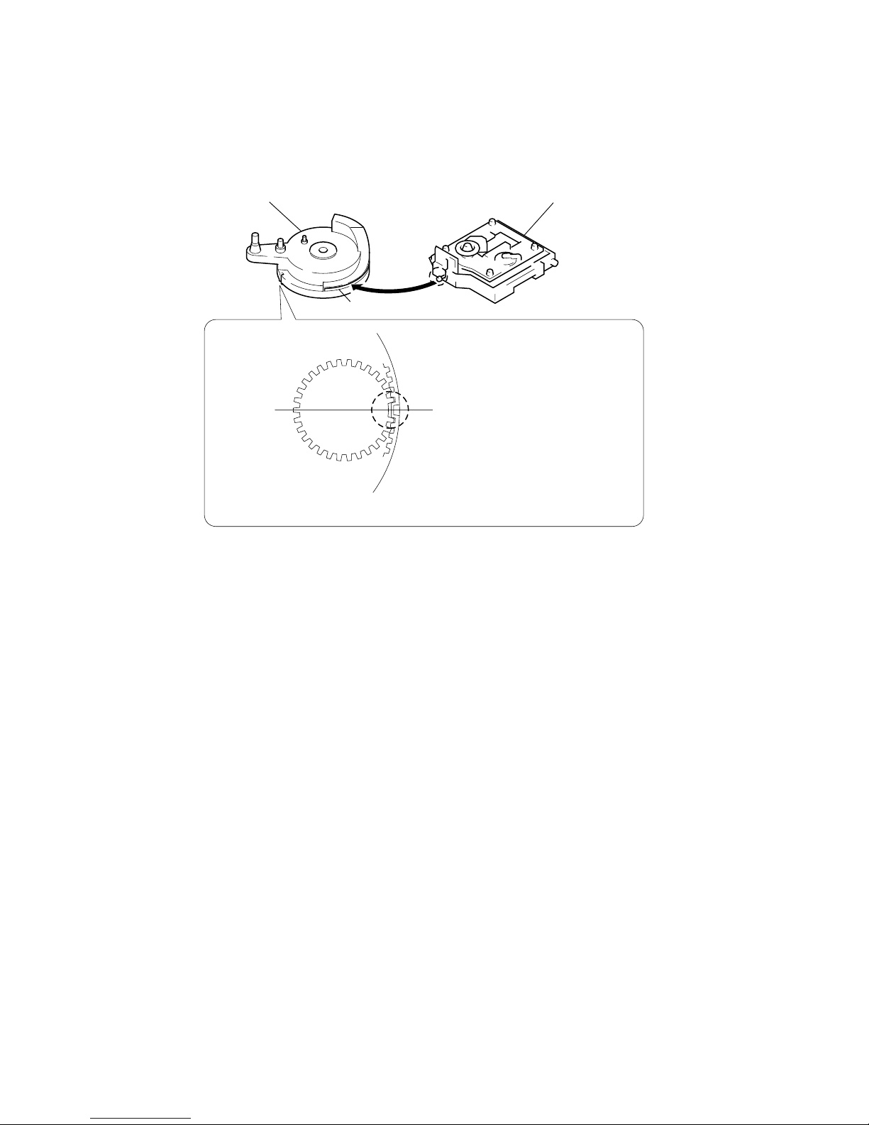
The laser diode in the optical pick-up block may suffer electrostatic
break-down because of the potential difference generated by the
charged electrostatic load, etc. on clothing and the human body.
During repair, pay attention to electrostatic break-down and also
use the procedure in the printed matter which is included in the
repair parts.
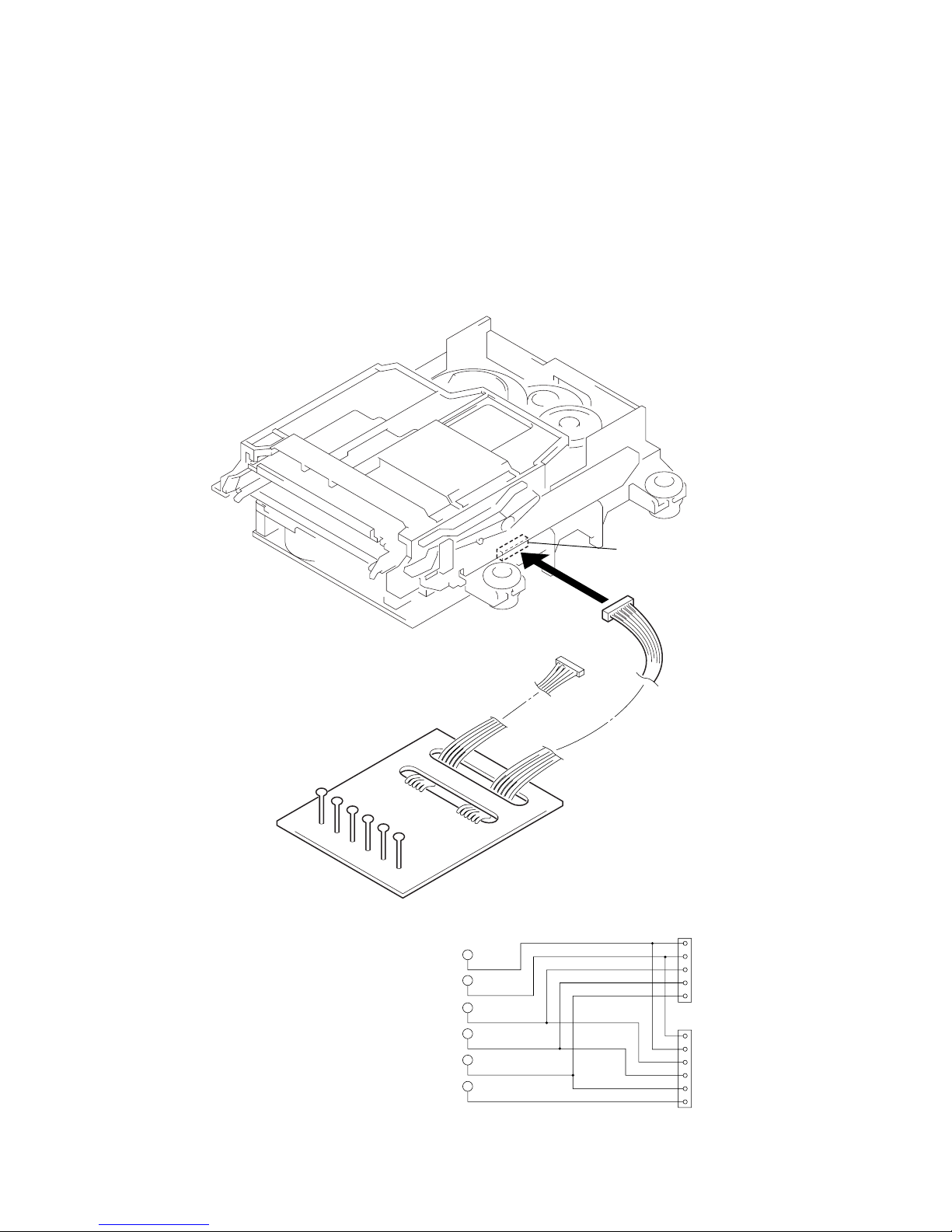
The flexible board is easily damaged and should be handled with
care.
NOTES ON LASER DIODE EMISSION CHECK
The laser beam on this model is concentrated so as to be focused on
the disc reflective surface by the objective lens in the optical pick-
up block. Therefore, when checking the laser diode emission,
observe from more than 30 cm away from the objective lens.
Notes on chip component replacement
•Never reuse a disconnected chip component.
•Notice that the minus side of a tantalum capacitor may be dam-
aged by heat.
Flexible Circuit Board Repairing
•Keep the temperature of the soldering iron around 270 ˚C dur-
ing repairing.
•Do not touch the soldering iron on the same conductor of the
circuit board (within 3 times).
•Be careful not to apply force on the conductor when soldering
or unsoldering.
NOTES ON HANDLING THE OPTICAL PICK-UP
BLOCK OR BASE UNIT
CAUTION
Use of controls or adjustments or performance of procedures
other than those specified herein may result in hazardous
radiation exposure.
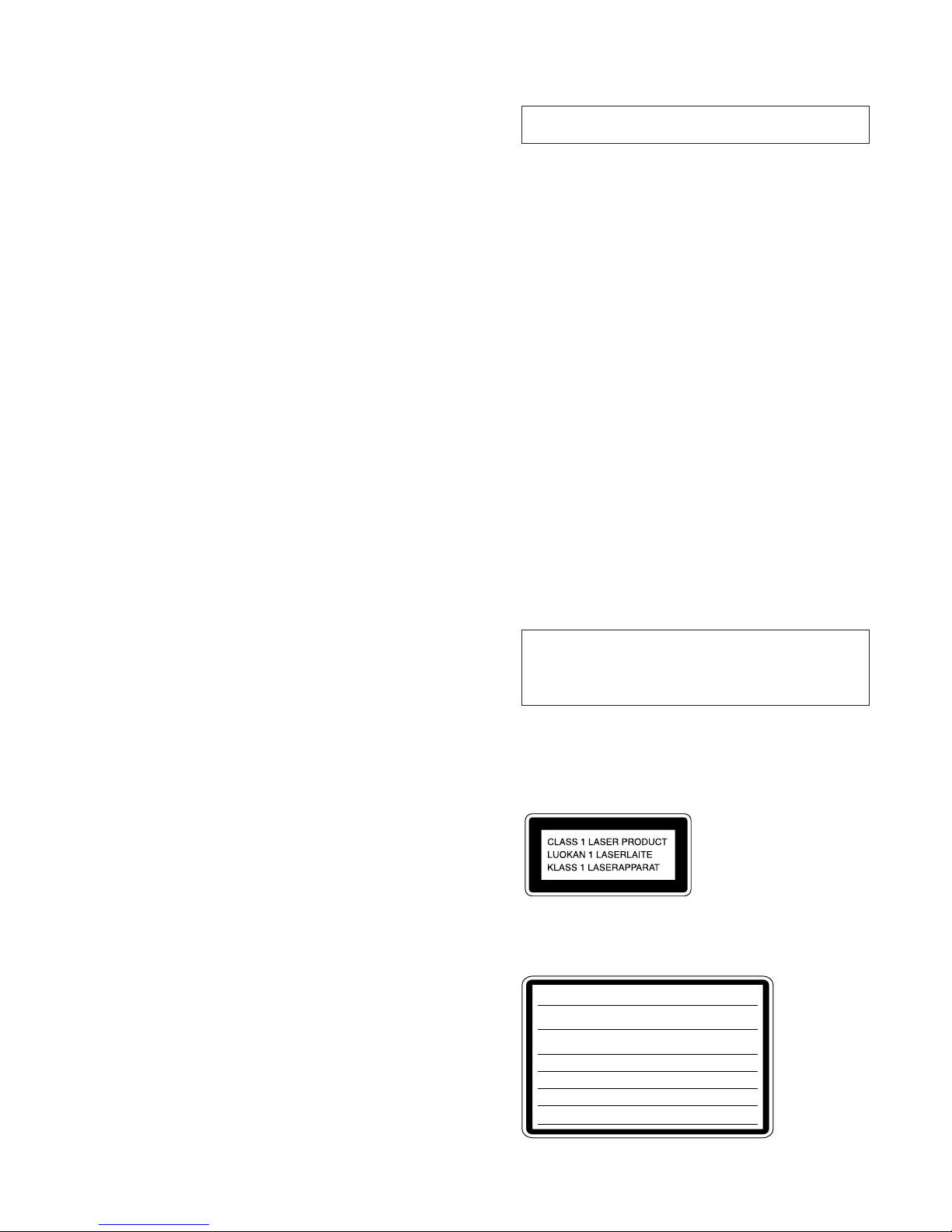
This appliance is classified as a CLASS 1 LASER product.
The CLASS 1 LASER PRODUCT MARKING is located on
the rear exterior.
Laser component in this product is capable of emitting radiation
exceeding the limit for Class 1.
The following caution label is located inside the unit.
CAUTION :
INVISIBLE LASER RADIATION WHEN OPEN AND
INTERLOCKS DEFEATED. AVOID EXPOSURE TO BEAM.
ADVARSEL :
USYNLIG LASERSTRÅLING VED ÅBNING NÅR
SIKKERHEDSAFBRYDERE ER UDE AF FUNKTION. UNDGÅ UDSAETTELSE
FOR STRÅLING.
VORSICHT :
UNSICHTBARE LASERSTRAHLUNG, WENN
ABDECKUNG GEÖFFNET UND SICHERUEITSVERRIEGELUNG
ÜBERBRÜCKT. NICHT DEM STRAHL AUSSETZEN.
VARO!:
AVATTAESSA JA SUOJALUKITUS OHITETTAESSA OLET ALT-
TIINA NÄKYMÄTTÖMÄLLE LASERSÄTEILYLLE. ÄLÄ KATSO SÄTEESEEN.
VARNING :
OSYNLING LASERSTRÅLING NÄR DENNA DEL ÄR ÖPPNAD
OCH SPÄRREN ÄR URKOPPLAD. BETRAKTA EJ STRÅLEN.
ADVERSEL :
USYNLIG LASERSTRÅLING NÅR DEKSEL ÅPNES OG
SIKKERHEDSLÅS BRYTES. UNNGÅ EKSPONERING FOR STRÅLEN.
VIGYAZAT!:
A BURKOLAT NYITÁSAKOR LÁTHATATLAN LÉZERSU-
GÁRVESZÉLY!KERÜLJE A BESUGÁRZÁST!

4
SAFETY-RELATED COMPONENT WARNING!!
COMPONENTS IDENTIFIED BY MARK 0OR DOTTED LINEWITH
MARK 0ON THE SCHEMATIC DIAGRAMS AND IN THE PARTS
LIST ARE CRITICAL TO SAFE OPERATION. REPLACE THESE
COMPONENTS WITH SONY PARTS WHOSE PART NUMBERS
APPEAR AS SHOWN IN THIS MANUAL OR IN SUPPLEMENTS
PUBLISHED BY SONY.
ATTENTION AU COMPOSANT AYANT RAPPORT
ÀLA SÉCURITÉ!
LES COMPOSANTS IDENTIFÉS PAR UNE MARQUE 0SUR LES
DIAGRAMMES SCHÉMATIQUES ET LA LISTE DES PIÈCES SONT
CRITIQUES POUR LA SÉCURITÉDE FONCTIONNEMENT. NE
REMPLACER CES COMPOSANTS QUE PAR DES PIÈSES SONY
DONT LES NUMÉROS SONT DONNÉS DANS CE MANUEL OU
DANS LES SUPPÉMENTS PUBLIÉS PAR SONY.
After correcting the original service problem, perform the
following safety checks before releasing the set to the customer:
Check the antenna terminals, metal trim, “metallized”knobs, screws,
and all other exposed metal parts for AC leakage. Check leakage as
described below.
LEAKAGE
The AC leakage from any exposed metal part to earth ground
and from all exposed metal parts to any exposed metal part having
a return to chassis, must not exceed 0.5 mA (500 microamperes).
Leakage current can be measured by any one of three methods.
1. A commercial leakage tester, such as the Simpson 229 or RCA
WT-540A. Follow the manufacturers’instructions to use these
instruments.
2. A battery-operated AC milliammeter. The Data Precision 245
digital multimeter is suitable for this job.
3. Measuring the voltage drop across a resistor by means of a
VOM or battery-operated AC voltmeter. The “limit”indication
is 0.75 V, so analog meters must have an accurate low-voltage
scale. The Simpson 250 and Sanwa SH-63Trd are examples of
a passive VOM that is suitable. Nearly all battery operated
digital multimeters that have a 2V AC range are suitable. (See
Fig. A)
SAFETY CHECK-OUT
To Exposed Metal
Parts on Set
0.15 µF1.5 kΩ
AC
Voltmeter
(0.75 V)
Earth Ground
Fig. A. Using an AC voltmeter to check AC leakage.
MODEL IDENTIFICATION
–Back Panel –
Power Voltage
Indication
VOLTAGE
SELECTOR Switch
(E, AR, HK, MY,
SP, TW, JE, KR,
model)
Power Voltage
Incdication
AC: 120 V 60 Hz 75 W
AC: 230 V 50 Hz 75 W
AC: 220 –240V 50/60 Hz 75 W
AC: 110 –120/
220 –240 V 50/60 Hz 75 W
Model
US, CND models
AEP, UK, AED models
AUS, TH models
E, AR, HK, MY, SP,
TW, JE, KR models
• Abbreviation
AUS : Australian model.
SP : Singapore model.
MY : Malaysia model.
TW : Taiwan model.
HK : Hong Kong model.
AR : Argentine model.
CND : Canadian model.
AED : North European model.
KR : Korean model.
TH : Thai model.
JE : Tourist model.

5
CD-TEXT
This unit is provided with a simple CD-TEXT display function.
The CD-TEXT contents of 50 tracks are displayed on the fluorescent display tube.
Since the function is simple, some special characters may not be displayed, or may be displayed as other characters.
SECTION 1
SERVICING NOTE
NOTE FOR INSTALLATION (ROTARY ENCODER)
BU cam
Groove
Section A
Note:When attaching the Base unit, Insert the
section A into the groove of BU cam.
Note:When attaching the BU cam,
engage the Rotary encoder
switch as shown in the figure.

6
JIG FOR CHECKING BD BOARD WAVEFORM
The special jig (J-2501-149-A) is useful for checking the waveform of the BD board. The names of terminals and the checking items to be
performed are shown as follows.
GND : Ground
I+3V : For measuring IOP (Check the deterioration of the optical pick-up laser)
IOP : For measuring IOP (Check the deterioration of the optical pick-up laser)
TEO : TRK error signal (Traverse adjustment)
VC : Reference level for checking the signal
RF : RF signal (Check jitter)
RF
VC
TEO For MDM-
3
For MDM-
5
IOP
I-3V
VC
RF
TEO
IOP
I+3V
GND
VC
RF
TEO
IOP
I+3V
GND
1
5
1
6
CN110
RF
5P connector
6P connecto
r
VC
TEO
IOP
I+3V
GND
Mechanism deck

7
Ver 1.1 2001. 08
IOP Data Recording and Display When optical Pick-up and Non-volatile Memory (IC171 of BD board) are
Replaced
The IOP value labeled on the optical pick-up can be recorded in the non-volatile memory. By recording the value, it will eliminate the need
to look at the value on the label of the optical pick-up. When replacing the optical pick-up or non-volatile memory (IC171 of BD board),
record the IOP value on the optical pick-up according to the following procedure.
Record Precedure:
1. With the power ON, press the CD xbutton while pressing the MD REC zand MD xbuttons together.
2. Press the .(R) , >(R) button to display “Service”, and press the ENTER/YES (R) button.
3. Press the .(R) , >(R) button to display “Iop Write”, and press the ENTER/YES (R) button.
4. The display changes to “Ref=@@@.@”(@ is an arbitrary number) and the digits which can be changed, blink.
5. Input the IOP value labeled on the optical pick-up.
To select the value : Press the .(R) , >(R) button.
6. When the ENTER/YES (R) button is pressed, the display changes to “Measu=###.#”(# is an arbitrary number).
7. The adjustment value that is obtained by the adjustment described in separate section of Manual, can be saved in this set up. However,
leave the value as it is and press the ENTER/YES (R) button.
8. “Complete!!”will be displayed momentarily. The value will be recorded in the non-volatile memory and the display will change to “Iop
Write”.
Display Precedure:
1. With the power ON, press the CD xbutton while pressing the MD REC zand MD xbuttons together.
2. Press the .(R) , >(R) button to display “Service”, and press the ENTER/YES (R) button.
3. Press the .(R) , >(R) button to display “Iop Read”, and press the ENTER/YES (R) button.
4. “@@.@/##.#”is displayed and the recorded contents are displayed.
@@.@ : indicates the Iop value labeled on the pick-up.
##.# : indicates the Iop value after adjustment
5. To end, press MENU/NO (R) button to display “Iop Read”.

8
•0.9 mW power
Specified value : 0.84 to 0.92 mW
•7.0 mW power
Specified value : 6.8 to 7.2 mW
lop (at 7mW)
•Labeled on the optical pickup
Iop value ± 10mA
•Traverse waveform
Specified value : Below 10% offset
•Error rate check
Specified value : For points a, b, and c
C1 error : Below 220
AD error : Below 2
•Error rate check
Specified value:
a.When using test disc (MDW-74/AU-1)
C1 error : Below 80
AD error : Below 2
b.When using check disc (TDYS-1)
C1 error : Below 50
•CPLAY error rate check
Specified value:
C1 error : Below 80
AD error : Below 2
•Unsatisfactory if displayed as T=@@ (##) NG
NG
(@@, ## are both arbitrary numbers)
Checks Prior to Parts Replacement and Adjustments
Before performing repairs, perform the following checks to determine the faulty locations up to a certain extent.
Details of the procedures are described in “6 Electrical Adjustments”.
Laser power check
Traverse check
Focus bias check
C PLAY check
Self-recording/playback
check
(REC/PLAY)
TEMP check
(Temperature
compensation
offset check)
Criteria for Determination
(Unsatisfactory if specified value is not satisfied)
•Clean the optical pick-up
•Adjust again
•Replace the optical pick-up
If always unsatisfactory:
•Replace the overwrite head
•Check for disconnection of the circuits around the
overwrite head
If occasionally unsatisfactory:
•Check if the overwrite head is distorted
•Check the mechanism around the sled
•Check for disconnection of the circuits around D101
(BD board)
•Check the signals around IC101, IC121, CN102, CN103
(BD board)
Measure if unsatisfactory:
Note:
The criteria for determination above is intended merely to determine if satisfactory or not, and does not serve as the specified value for
adjustments.
When performing adjustments, use the specified values for adjustments.

9
Reading the Display:
Convert the hexadecimal display into binary display. If more than two causes, they will be added.
Example
When 42 is displayed:
Higher bit : 4 = 0100 nb6
Lower bit : 2 = 0010 nb1
In this case, the retry cause is combined of “CLV unlock”and “ader5”.
When A2 is displayed:
Higher bit : A = 1010 nb7+b5
Lower bit : 2 = 0010 nb2
The retry cause in this case is combined of “access fault”, “IVR rec error”, and “ader5”.
Retry Cause Display Mode
•In this test mode, the causes for retry of the unit during recording can be displayed on the fluorescent indicator tube. During playback,
the “track mode”for obtaining track information will be set.
This is useful for locating the faulty part of the unit.
•The following will be displayed :
During recording and stop : Retry cause, number of retries, and number of retry errors.
During playback : Information such as type of disc played, part played, copyright.
These are displayed in hexadecimal.
Precedure:
1. Load a recordable disc whose contents can be erased into the unit.
2. Press the FUNCTION button and set the function to “MD”.
3. Press the MENU/NO button. When “Edit/Menu”is displayed on the fluorescent indicator tube, rotate the AMS dial to display “All
Erase?”.
4. Press the ENTER/YES button.
5. “All Erase??”is displayed on the fluorescent indicator tube.
6. Press the ENTER/YES button to display “Complete!!”, and press the xbutton immediately. Wait for about 10 seconds while pressing
the button.
7. When the “TOC”displayed on the fluorescent display tube goes off, release the xbutton.
8. Press the MD REC zbutton to start recording. Then press the MD ubutton and start recording.
9. To check the “track mode”, press the MD ubutton to start play.
10. To exit the test mode, press the ?/1button, and turn OFF the power. When “TOC”disappears, disconnect the power plug from the
outlet. If the test mode cannot be exited, refer to “Forced Reset”on page 8.
} Address (Physical address on disc)
Fig. 1 Reading the Test Mode Display
(During recording and stop)
RTs@@c##c**
Fluorescent display tube display
@@ : Cause of retry
## : Number of retries
** : Number of retry errors
Fig. 2 Reading the Test Mode Display
(During playback)
@@####**$$
Fluorescent display tube display
@@ : Parts No. (name of area named on TOC)
## : Cluster
** : Sector
$$ : Track mode (Track information such as copyright
information of each part)
Reading the Retry Cause Display
Hexadecimal
Bit
Binary
84218421
b7 b6 b5 b4 b3 b2 b1 b0
00000001
00000010
00000100
00001000
00010000
00100000
01000000
10000000
Higher Bits Lower Bits
Hexa-
decimal Cause of Retry Occurring conditions
shock
ader5
Discontinuous adress
DIN unlock
FCS incorrect
IVR rec error
CLV unlock
Access fault
When track jump (shock) is detected
When ADER was counted more than five times
continuously
When ADIP address is not continuous
When DIN unlock is detected
When not in focus
When ABCD signal level exceeds the specified range
When CLV is unlocked
When access operation is not performed normally
01
02
04
08
10
20
40
80

10
Hexadecimal
Bit
Binary
Higher Bits Lower Bits
84218421
b7 b6 b5 b4 b3 b2 b1 b0
00000001
00000010
00000100
00001000
00010000
00100000
01000000
10000000
Hexa-
decimal
Details
01
02
04
08
10
20
40
80
Emphasis OFF
Monaural
This is 2-bit display. Normally 01.
01:Normal audio. Others:Invalid
Audio (Normal)
Original
Copyright
Write prohibited
When 0 When 1
Emphasis ON
Stereo
Invalid
Digital copy
No copyright
Write allowed
Reading the Display:
Convert the hexadecimal display into binary display. If more than two causes, they will be added.
Example When 84 is displayed:
Higher bit : 8 = 1000 nb7
Lower bit : 4 = 0100 nb2
In this case, as b2 and b7 are 1 and others are 0, it can be determined that the retry cause is combined of “emphasis OFF”, “monaural”,
“original”, “copyright exists”, and “write allowed”.
Example When 07 is displayed:
Higher bit : 0 = 1000 nAll 0
Lower bit : 7 = 0111 nb0+b1+b2
In this case, as b0, b1, and b2 are 1 and others are 0, it can be determined that the retry cause is combined of “emphasis ON”, “stereo”,
“original”, “copyright exists”, and “write prohibited”.
Hexadecimal
n
Binary Conversion Table
Hexadecimal Binary Hexadecimal Binary
0
1
2
3
4
5
6
7
0000
0001
0010
0011
0100
0101
0110
0111
1000
1001
1010
1011
1100
1101
1110
1111
Reading the Track Mode Display
8
9
A
B
C
D
E
F

11
SECTION 2
GENERAL
LOCATION OF CONTROLS
•Front View
•Rear View
124
3
5
6
9
q;
qf
qj
qa
qg
qkqlwg
wk
wl
wh
wj
wd
wf
7
8
qh
qd
qs
w;waws
2 1
5
3
4
Photo: US model
1TAPE deck
2Liquid crystal display
3TAPE Ybutton
4TAPE Zbutton
5TAPE xbutton
6TAPE Xbutton
7TAPE REC zbutton
8DSG button and indicator
9VOLUME knob
0MD 6button
!¡ MD xbutton
!™ MD ubutton
!£ MD REC zbutton
!¢ CD 6button
!∞ CD xbutton
!§ CD ubutton
!¶ CD >button
!• CD .button
!ª TUNER/BAND button
@º REPEAT DOLBY NR button and indicator
@¡ PLAY MODE DIRECTION button and indicator
@™ FUNCTION button and indicator
@£ ENTER/START button and indicator
@¢ SYNCHRO REC button and indicator
@∞ PHONES jack
@§ ?/1 button and indicator
@¶ Remote sensor
@• BASS knob
@ª TREBLE knob
1FM ANTENNA terminals
2AM LOOP ANTENNA terminals
3LINE OUT jacks
4VIDEO IN jacks
5SPEAKER terminals

12
This section is extracted from
instruction manual.
Step 2: Setting the time
You must set the time beforehand to use the timer
functions.
The clock is on a 24-hour system for the European
model, and a 12-hour system for other models.
The 24-hour system is used for illustration
purposes.
x
.>
N
`/1
X
M
m
4,6
3,5 3,5
2
1
4
DISPLAY
CURSORT
1Turn on the system.
2Press CLOCK/TIMER SET.
The clock appears and the hour indication
flashes.
3Press .or >to set the hour.
4Press ENTER/YES or CURSORt.
The minute indication flashes.
5Press .or >to set the minute.
6Press ENTER/YES.
The clock starts.
If you made a mistake
Press CURSORTor trepeatedly until the
incorrect item flashes, then set it again.
To change the preset time
You can change the preset time while the system
is off.
1Press DISPLAY to display the clock.
2Press CLOCK/TIMER SET.
3Repeat steps 3 to 6 of “Setting the time.”
Tip
The upper dot of the colon flashes for the first
30 seconds, and the lower dot flashes for the last
30 seconds of each minute.

13
3-1. COVER (UPPER)
3-2. TAPE MECHANISM DECK
Note: Follow the disassembly procedure in the numerical order given.
SECTION 3
DISASSEMBLY
1Two screws
(case3 TP2)
4Cover (upper)
2Four screws
(BTP3 ×8)
3Two screws
(case3 TP2
)
2
Connecto
r
5
Tape
mechanism deck
1
Flat wire (12 core)
3
Two screws
(BTP3
×
8)
4
Two screws
(BTP3
×
8)

14
3-3. FRONT PAENL SECTION
1Connector
(CN303)
2Flat wire
Two claws
5Screw
(KTP3 ×6)
6Front panel section
(There is a claw.)
4Two screws
(BTP3 ×8)
3Screw
(KTP3 ×6)
3-4. MD MECHANISM DECK
1Screw
(BTP3 ×8)
2Screw
(BTP3 ×8)

15
3-5. DIGITAL BOARD
6Two screws
(+PTPWHM 2.6)
3Digital board
7Screw
(+BVTP 3 ×8)
8
8
4
4
5Two screws
(+PTPWHM 2.6)
1Screw
(+BVTP 3 ×8)
2Harness
1Screw
(+BVTP 3 ×8)
MD LID
MD LID TORSION SPRING
3Screw
(BTP3 ×8)
2flat wire (19 core)
(CN805)
1connecto
r
4CD mechanism deck
3-6. CD MECHANISM DECK

16
3-8. TRAY
1
Screw
(+BTP 3
×
8)
2
Upper chassis
4Motor board
3Two screws
(+BTP 2.6 ×6)
2Belt
1Rotate the control cam in
the direction of arrow A
5Pull the tray
A
3-7. UPPER CHASSIS

17
3-9. CAM
3-10. SLIDER (CAM)
1
Two screws (BTP2.6x6)
2
Bracket (Guide L)
3
Leaf spring
5
Bracket (Guide R)
6
Slider (Cam)
4
Two screws (BTP2.6x6)
Set the shaft of Lever (O/C) to
be at the position in the figure.
Set the shaft of Cam gear to
be at the position in the figure.
1
Torsion spring
2
SW lever
3
Pulley
5
Gear
6
Gear
7
Roller
8
Cam
4
Spacer (55)

18
3-11. BASE UNIT (MBU-5A) AND BD (MD) BOARD
3-12. SW BOARD AND LOADING MOTOR (M103)
5
Two screws (BTP2.6x6)
6
SW board
4
Loading motor (M103)
3
Two screws
(PWH1.7x3)
1
Screw (PTPWH M2.6x6)
2
Gear B
1
Three screws
(BTP2.6x6)
2
Base unit (MBU-5A)
3
Remove the solder (Five portion)
4
Screw (M1.7x4)
6
Flexible board
(CN101)
7
BD (MD) board
5
Flexible board
(CN104)

19
SECTION 4
SERVICE MODE
Start
REC pause for 3 seconds
FWD REC
Fast forward
REV Play
REC pause for 3 seconds
REV REC
Rewind
FWD Play Shut off
Shut off
Shut off
Shut off
1 minute
3 minutes
1 minute
3 minutes
Start
Open the disc tray
Close the disc tray
Play the last track
[Panel Test Mode]
Procedure:
1. Set to standby state.
2. Press three buttons of PLAY MODE DIRECTION , CD x,
and DSG simultaneously.
3. Liquid crystal display and LED are all turned on.
4. Pless MD Zto enter the version display mode. (destination,
MC, CD, ST, TC, TA, TM)
5. Press MD u to enter the KEY, VOL, check mode. ( m
.and M >must be pressed for several seconds.)
6. To exit from this mode, press the buttons in the same way as
step 2.
[Tape Deck Aging Mode]
This mode can be used for operation check of tape deck section.
Procedure:
1. Set a tape in the tape deck.
2. Set to standby state.
3. Press three buttons of TAPE x, CD x, (CD), and TAPE
simultaneously.
4. The aging is executed in bellow sequence.
5. To exit from the aging mode, press the ?/1 button to turn the
power OFF.
Aging mode sequence:
[CD Aging Mode]
This mode can be used for operation check of CD section.
Procedure:
1. Load a CD disc.
2. Set to standby state.
3. Press three buttons of TAPE x, CD x, and TUNER
simultaneously.
4. The aging is executed in bellow sequence.
5. To exit from the aging mode, press the ?/1 button to turn the
power OFF.
Aging mode sequence:
[Cold Reset]
Clears all the memories and starts up the machine again.
Procedure:
1. POWEWR ON state is in progress.
2. Press three buttons of CD x, PLAY MODE DIRECTION ,
and MD Z simultaneously.
[Hot Reset]
Starts up the machine again holding the memory data.
Procedure:
1. POWEWR ON state is in progress.
2. Press three buttons of CD x, PLAY MODE DIRECTION ,
and MD u simultaneously.

20
SECTION 5
TEST MODE (MD)
5-1. PRECAUTIONS FOR USE OF TEST MODE
• Use the RM-SJ373 supplied remote control (R).
• As loading related operations will be performed regardless of the test mode operations being performed, be sure to check that the disc
is stopped before setting and removing it.
Even if the MD Zbutton is pressed while the disc is rotating during continuous playback, continuous recording, etc., the disc will not
stop rotating.
Therefore, it will be ejected while rotating.
Be sure to press the MD Zbutton after pressing the MENU/NO (R) button and the rotation of disc is stopped.
5-1-1. Recording laser emission mode and operating buttons
• Continuous recording mode (CREC MODE)
• Laser power check mode (LDPWR CHECK)
• Laser power adjustment mode (LDPWR ADJUST)
• Traverse (MO) check (EF MO CHECK)
• Traverse (MO) adjustment (EF MO ADJUST)
• When pressing the MD REC zbutton.
5-2. SETTING THE TEST MODE
The following are two methods of entering the test mode.
Procedure 1: With the power ON, press the CD xbutton while pressing the MD xand MD REC zbuttons together.
When the test mode is set, “Check” will be displayed. .(R) , > (R) switches between the following four groups;
···Nn Check Nn Adjust Nn Service Nn Develop Nn ···.
Procedure 2: With the power ON, press the CD xbutton while pressing the MD xand SYNCHRO REC buttons together.
When the test mode is set, “TEMP CHECK” will be displayed. By setting the test mode using this procedure, only the “Check”
group of procedure 1 can be executed.
5-3. EXITING THE TEST MODE
Press the button, ?/1
5-4. BASIC OPERATIONS OF THE TEST MODE
All operations are performed using the .(R) , > (R) , ENTER/YES (R) button, and MENU/NO (R) button.
The functions of these buttons are as follows.
Function name
.(R) > (R)
ENTER/YES (R) button
MENU/NO (R) button
Function
Changes parameters and modes
Proceeds onto the next step. Finalizes input.
Returns to previous step. Stops operations.
[MC Cold Reset]
Clears the MD memory.
Procedure:
1. POWEWR ON. FUNCTION MD.
2. Press CD x, MD xand REPEAT simultaneously.
[MD SERVICE END]
Ends the service mode and clears the nonvolatile moemory.
Procedure:
1. The service mode is in progress.
2. Press CD x, MD xand ENTER/START simultaneously.
[MD FLASH UP-DATE]
Writes data in the FLASH ROM from the disk.
Procedure:
1. POWER ON.
2. Press CD x, MD xand ?/1 simultaneously.
Table of contents
Other Sony Stereo System manuals

Sony
Sony LBT-A199 User manual

Sony
Sony CMT-EH10 User manual

Sony
Sony hcd-grx40av User manual

Sony
Sony LBT-G1 User manual

Sony
Sony HCD-EH15 User manual

Sony
Sony MHC-V21 User manual

Sony
Sony CMT-CP101 - Micro Hi Fi Component System User manual

Sony
Sony LBT-D117CD User manual

Sony
Sony HCD-ZT4 User manual

Sony
Sony HCD-GP6V User manual

Sony
Sony FST-GTK11iP User manual

Sony
Sony HTC-VX500 User manual

Sony
Sony Aiwa CX-JN20 User manual

Sony
Sony MHC-VX55 User manual

Sony
Sony HCD-EP414 User manual

Sony
Sony HCD-G2500 User manual

Sony
Sony CMT-CP11 User manual

Sony
Sony PHC-Z10 Primary User manual

Sony
Sony HCD-551 User manual

Sony
Sony HCD-E301 User manual