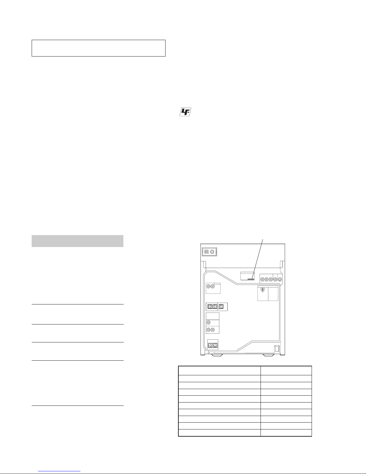
Sony HCD-GNV99D User manual

HCD-GNV99D/
GNV111D
E Model
HCD-GNV99D/GNV111D
Australian Model
HCD-GNV111D
SERVICE MANUAL
MiNi Hi-Fi COMPONENT SYSTEM
Sony Corporation
Audio Group
Published by Sony Engineering Corporation
9-879-585-02
2005E02-1
© 2005.05
SPECIFICATIONS
Ver.1.1 2005.05
– Continued on next page –
•HCD-GNV99D/GNV111D are the Amplifier,
DVD player, tape deck and tuner
section in MHC-GNV99D/GNV111D.
DVD
Model Name Using Similar Mechanism NEW
DVD Mechanism Type CDM74H-DVBU101
Section
Optical Pick-up Name KHM-310CAB/C2NP
TAPE Model Name Using Similar Mechanism NEW
Section Tape Transport Mechanism Type CMAT2E2
Photo : HCD-GNV111D
Inputs
VIDEO INPUT: VIDEO: 1 Vp-p, 75 ohms
(phono jacks) AUDIO L/R: Voltage
250 mV, impedance 47 kilohms
TV/SAT AUDIO IN L/R: voltage 250 mV/450 mV,
(phono jacks) impedance 47 kilohms
MIC 1/2: sensitivity 1 mV,
(phone jack) impedance 10 kilohms
Outputs
AUDIO OUT: Voltage 250 mV
(phono jacks) impedance 1 kilohm
VIDEO OUT: max. output level 1 Vp-p,
(phono jack) unbalanced, Sync.
negative load impedance 75 ohms
COMPONENT VIDEO
OUT: Y: 1 Vp-p, 75 ohms
PB/CB: 0.7 Vp-p, 75 ohms
PR/CR: 0.7 Vp-p, 75 ohms
S VIDEO OUT: Y: 1 Vp-p, unbalanced,
(4-pin/mini-DIN jack) Sync. negative
C: 0.286 Vp-p load impedance 75 ohms
PHONES: accepts headphones of
(stereo mini jack) 8 ohms or more
FRONT SPEAKER: Use only the supplied speakers
SURR SPEAKER: Use only the supplied speakers
CENTER SPEAKER: Use only the supplied speaker
SUBWOOFER OUT: Voltage 250 mV
(phono jack) impedance 1 kilohm
Amplifier section
HCD-GNV111D
The following are measured at AC 120, 127, 220, 240V 50/60 Hz
DIN power output (rated)
Front speaker: 110 W + 110 W
(6 ohms at 1 kHz, DIN)
Center speaker: 50 W
(16 ohms at 1 kHz, DIN)
Surround speaker: 110 W + 110 W
(6 ohms at 1 kHz, DIN)
Continuous RMS power output (reference)
Front speaker: 160 W + 160 W
(6 ohms at 1 kHz, 10% THD)
Center speaker: 80 W
(16 ohms at 1 kHz, 10% THD)
Surround speaker: 160 W + 160 W
(6 ohms at 1 kHz, 10% THD)
HCD-GNV99D
The following are measured at AC 120, 127, 220, 240V 50/60 Hz
DIN power output (rated)
Front speaker: 130 W + 130 W
(6 ohms at 1 kHz, DIN)
Center speaker: 30 W
(8 ohms at 1 kHz, DIN)
Surround speaker: 30 W + 30 W
(8 ohms at 1 kHz, DIN)
Continuous RMS power output (reference)
Front speaker: 180 W + 180 W
(6 ohms at 1 kHz, 10% THD)
Center speaker: 50 W
(8 ohms at 1 kHz, 10% THD)
Surround speaker: 50 W + 50 W
(8 ohms at 1 kHz, 10% THD)

2
HCD-GNV99D/GNV111D
Notes on chip component replacement
•Never reuse a disconnected chip component.
•Notice that the minus side of a tantalum capacitor may be
damaged by heat.
Flexible Circuit Board Repairing
•Keep the temperature of soldering iron around 270˚C
during repairing.
•Do not touch the soldering iron on the same conductor of the
circuit board (within 3 times).
•Be careful not to apply force on the conductor when soldering
or unsoldering.
CAUTION
Use of controls or adjustments or performance of procedures
other than those specified herein may result in hazardous
radiation exposure.
This appliance is classified as
a CLASS 1 LASER product.
This label is located on the rear
exterior.
SAFETY-RELATED COMPONENT WARNING!!
COMPONENTS IDENTIFIED BY MARK 0OR DOTTED LINE WITH
MARK 0ON THE SCHEMATIC DIAGRAMS AND IN THE PARTS
LIST ARE CRITICAL TO SAFE OPERATION. REPLACE THESE
COMPONENTS WITH SONY PARTS WHOSE PART NUMBERS
APPEAR AS SHOWN IN THIS MANUAL OR IN SUPPLEMENTS
PUBLISHED BY SONY.
Disc player section
System Compact disc and digital audio and video
system
Laser Semiconductor laser
(DVD: λ= 650 nm, CD: λ= 790 nm)
Emission duration: continuous
Frequency response DVD (PCM 48 kHz):
2 Hz – 22 kHz (±1dB)
CD: 2 Hz – 20 kHz (±0.5 dB)
Video color system format
NTSC and PAL
Tape deck section
Recording system 4-track 2-channel stereo
Frequency response 50 – 13,000 Hz (±3 dB), using Sony TYPE I
tape
Tuner section
FM stereo, FM/AM superheterodyne tuner
FM tuner section
Tuning range 87.5 – 108.0 MHz (50 kHz step)
Antenna FM lead antenna
Antenna terminals 75 ohms unbalanced
Intermediate frequency 10.7 MHz
AM tuner section
Tuning range
Saudi Arabian model: 531– 1,602 kHz
(with the interval set at 9 kHz)
Other models: 531 – 1,602 kHz
(with the interval set at 9 kHz)
530 – 1,710 kHz
(with the interval set at 10 kHz)
Antenna AM loop antenna
Antenna terminals External antenna terminal
Intermediate frequency 450 kHz
General
Power requirements
Australian model: 230 – 240 V AC, 50/60 Hz
Mexican model: 127 V AC, 60Hz
Saudi Arabian model: 120 – 127 V, 220 V or
230 – 240 V AC, 50/60 Hz
Adjustable with voltage selector
Other models: 120 V, 220 V or
230 – 240 V AC, 50/60 Hz
Adjustable with voltage selector
Power consumption
MHC-GNV111D 380 W
MHC-GNV99D 285 W
Dimensions (w/h/d) (Approx.)
HCD-GNV111D 280 ×371 ×398.5 mm
HCD-GNV99D 280 ×360 ×398.5 mm
Mass (Approx.)
HCD-GNV111D 16.1 kg
HCD-GNV99D 15.2 kg
Design and specifications are subject to change without notice.
Ver. 1.1

3
HCD-GNV99D/GNV111D
1. SERVICING NOTES ................................................ 4
2. GENERAL ................................................................... 6
3. DISASSEMBLY
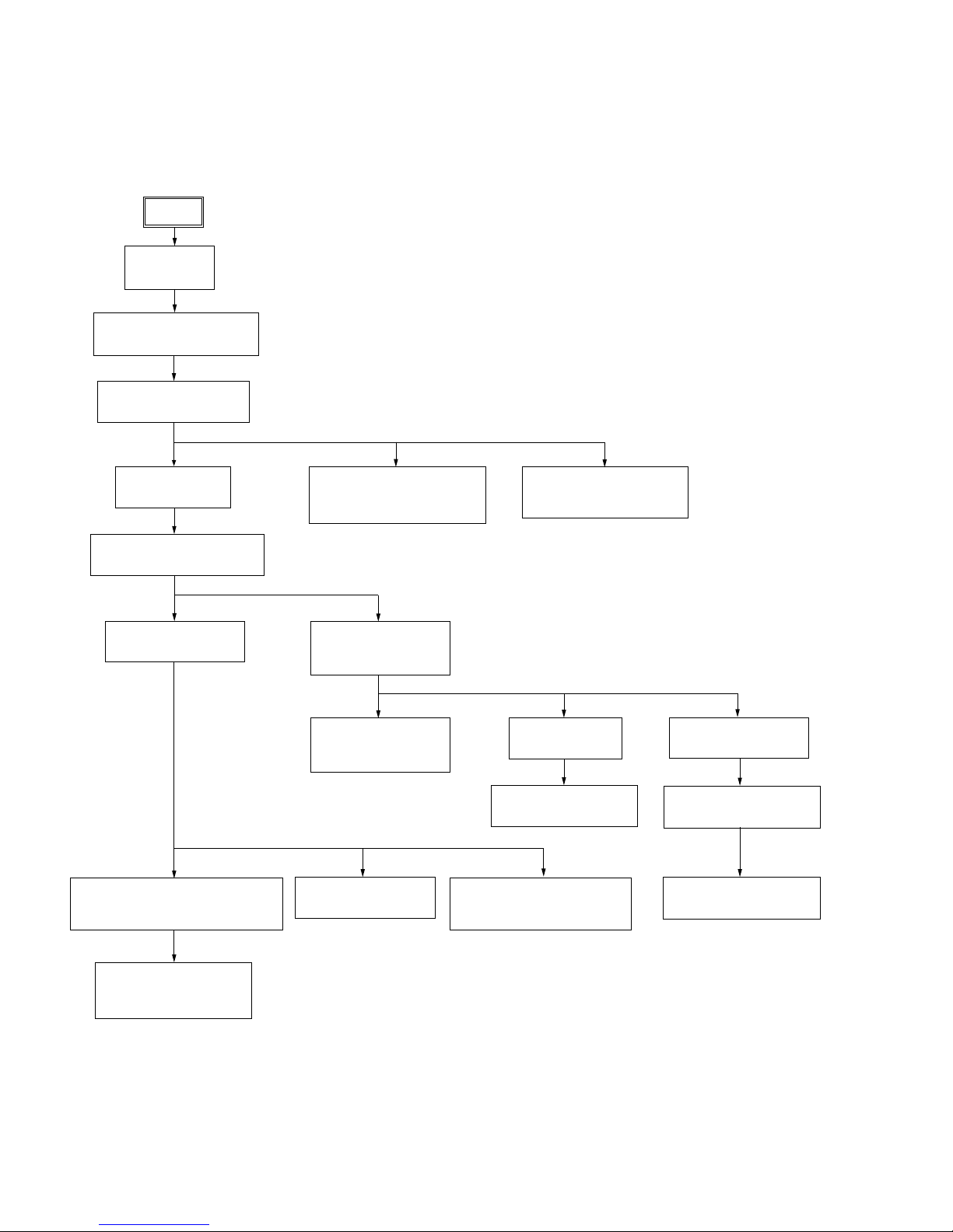
3-1. Disassembly Flow ........................................................... 8
3-2. Case ................................................................................. 9
3-3. Loading Panel Assy ......................................................... 9
3-4. Front Panel Assy .............................................................. 10
3-5. Tuner Pack ....................................................................... 11
3-6. Tape Mechanism Deck, MIC Board ................................ 12
3-7. Panel Board, CD-SW Board ............................................ 13
3-8. DVD Mechanism Deck ................................................... 14
3-9. Video Board, DMB10 Board ........................................... 15
3-10. Back Panel ....................................................................... 16
3-11. Primary Board ................................................................. 16
3-12. Power Amp PC Board Assy, Main Board ........................ 17
3-13. DVD SURR Board, PA Board ......................................... 17
3-14. Power Transformer (T1200) ............................................ 18
3-15. Driver Board, SW Board ................................................. 18
3-16. DVD Assy ........................................................................ 19
3-17. Optical Pick-up ................................................................ 19
3-18. Sensor Board ................................................................... 20
3-19. Motor (TB) Board ........................................................... 20
3-20. Motor (LD) Board ........................................................... 21
4. TEST MODE ............................................................... 22
5. MECHANICAL ADJUSTMENTS......................... 27
6. ELECTRICAL ADJUSTMENTS .......................... 27
TABLE OF CONTENTS
7. DIAGRAMS .......................................................... 29
7-1. Block Diagram – RF Section – ....................................... 30
7-2. Block Diagram – Video Section – ................................... 31
7-3. Block Diagram – Tape/Tuner Section – .......................... 32
7-4. Block Diagram – Main Section – .................................... 33
7-5. Block Diagram – AMP Section – .................................... 34
7-6. Block Diagram – Display/Power Section – ..................... 35
7-7. Printed Wiring Board – DMB10 Board (Side A) – ......... 36
7-8. Printed Wiring Board – DMB10 Board (Side B) – ........ 37
7-9. Schematic Diagram – DMB10 Board (1/4) – ................ 38
7-10. Schematic Diagram – DMB10 Board (2/4) – ................ 39
7-11. Schematic Diagram – DMB10 Board (3/4) – ................ 40
7-12. Schematic Diagram – DMB10 Board (4/4) – ................ 41
7-13. Printed Wiring Boards – CD Mechanism Boards – ....... 42
7-14. Schematic Diagram – CD Mechanism Boards – ........... 43
7-15. Printed Wiring Board – Main Board – ............................ 44
7-16. Schematic Diagram – Main Board (1/5) – ..................... 45
7-17. Schematic Diagram – Main Board (2/5) – ..................... 46
7-18. Schematic Diagram – Main Board (3/5) – ..................... 47
7-19. Schematic Diagram – Main Board (4/5) – ..................... 48
7-20. Schematic Diagram – Main Board (5/5) – ..................... 49
7-21. Printed Wiring Board – Panel Board – ............................ 50
7-22. Schematic Diagram – Panel Board – .............................. 51
7-23. Printed Wiring Boards – CD-SW, JOG
And MIC Boards – .......................................................... 52
7-24. Schematic Diagram – CD-SW, JOG
And MIC Boards – .......................................................... 53
7-25. Printed Wiring Board – PA Board – ................................ 54
7-26. Schematic Diagram – PA Board – .................................. 55
7-27. Printed Wiring Board – DVD SURR Board – ................. 56
7-28. Schematic Diagram – DVD SURR Board – ................... 57
7-29. Printed Wiring Board – Video Board – ........................... 58
7-30. Schematic Diagram – Video Board – ............................. 59
7-31. Printed Wiring Boards – Trans And Primary Boards – ... 60
7-32. Schematic Diagram – Trans And Primary Boards – ....... 61
8. EXPLODED VIEWS
8-1. Case, Rear Panel Section ................................................. 73
8-2. Front Panel Section ......................................................... 74
8-3. Chassis Section ................................................................ 75
8-4. DVD Mechanism Section-1 (CDM74H-DVBU101) ...... 76
8-5. DVD Mechanism Section-2 (CDM74H-DVBU101) ...... 77
9. ELECTRICAL PARTS LIST ....................... 78
Ver. 1.1

4
HCD-GNV99D/GNV111D
SECTION 1
SERVICING NOTES
NOTES ON HANDLING THE OPTICAL PICK-UP BLOCK
OR BASE UNIT
The laser diode in the optical pick-up block may suffer electrostatic
break-down because of the potential difference generated by the
charged electrostatic load, etc. on clothing and the human body.
During repair, pay attention to electrostatic break-down and also
use the procedure in the printed matter which is included in the
repair parts.
The flexible board is easily damaged and should be handled with
care.
NOTES ON LASER DIODE EMISSION CHECK
The laser beam on this model is concentrated so as to be focused on
the disc reflective surface by the objective lens in the optical pick-
up block. Therefore, when checking the laser diode emission,
observe from more than 30 cm away from the objective lens.
LASER DIODE AND FOCUS SEARCH OPERATION
CHECK
Carry out the “S curve check” in “CD section adjustment” and check
that the S curve waveform is output several times.
NOTE ON REPLACEMENT OF DMB10 BOARD
New part of EEPROM (IC103) on the DMB10 board can not be
used. Therefore, if the mounted DMB10 board (A-1099-272-A or
A-1099-344-A or A-1115-347-A) is replaced, exchange new
EEPROM with that used before the replacement.
UNLEADED SOLDER
Boards requiring use of unleaded solder are printed with the lead-
free mark (LF) indicating the solder contains no lead.
(Caution: Some printed circuit boards may not come printed with
the lead free mark due to their particular size)
: LEAD FREE MARK
Unleaded solder has the following characteristics.
•Unleaded solder melts at a temperature about 40 °C higher
than ordinary solder.
Ordinary soldering irons can be used but the iron tip has to be
applied to the solder joint for a slightly longer time.
Soldering irons using a temperature regulator should be set to
about 350 °C.
Caution: The printed pattern (copper foil) may peel away if
the heated tip is applied for too long, so be careful!
•Strong viscosity
Unleaded solder is more viscou-s (sticky, less prone to flow)
than ordinary solder so use caution not to let solder bridges
occur such as on IC pins, etc.
•Usable with ordinary solder
It is best to use only unleaded solder but unleaded solder may
also be added to ordinary solder.
When the self-diagnosis function is activated to
prevent the system from malfunctioning, a 5-
character service number (e.g., C 13 50) with a
combination of a letter and 4 digits appears in
the on-screen display and the front panel
Self-diagnosis Function
(When letters/numbers appear in the
display)
First 3
characters of
the service
number
Cause and/or corrective action
C 13 The disc is dirty.
•Cleanthe disc with a soft cloth
(page xx).
C 31 The disc is not inserted correctly.
•Restartthe system, then re-insert
the disc correctly.
E XX
(xx is a number)
To prevent a malfunction, the
system has performed the self-
diagnosis function.
•Contact your nearest Sony
dealer or local authorized Sony
service facility and give the 5-
character service number.
Example: E 61 10
display. In this case, check the following table.
•MODEL IDENTIFICATION
– Back Panel –
PART No.
MODEL PART No.
GNV99D : E3, E15 models 2-584-723-0[]
GNV111D : E2 model 2-584-724-0[]
GNV99D : EA model 2-596-940-0[]
GNV99D : PH model 2-596-941-0[]
GNV111D : MY, SP models 2-596-943-0[]
GNV111D : EA model 2-596-944-0[]
GNV111D : E3, E15 models 2-596-945-0[]
GNV111D : AUS model 2-596-946-0[]
GNV111D : PH model 2-596-947-0[]

5
HCD-GNV99D/GNV111D
J-2501-102-A
(1mm/13p/L300)
J-2501-086-A
(1mm/19p/L300)
DMB10 board
MAIN boar
d
DVD mechanism deck
CN521
CN520
CN106
CN302
front panel assy
TCM block
CN509
CN508
back panel
PA board
PANEL board
MAIN board DVD SURR board
J-2501-167-A
(1.25mm/17p/L300)
J-2501-077-A
(1.25mm/13p/L300)
• Service Position-1 (DMB10 Board)
• Service Position-2 (PA and DVD SURR Boards)

6
HCD-GNV99D/GNV111D
SECTION 2
GENERAL This section is extracted
from instruction manual.
LOCATING THE CONTROLS
AMP MENU ef
AUTO/MANUAL
*
2
CD SYNC qd
Deck A es
Deck B ws
DIRECTION qk
DISC 1 ~ 3 7
Disc tray 9
DISPLAY rf
Display rg
DVD r;
ECHO LEVEL wf
ENTER wa
EQ BAND qa
EX-CHANGE/DISC SKIP 6
GROOVE ej
ILLUMINATION rd
IR Receptor ra
MASTER VOLUME 8
MIC 1 (jack) wj
MIC 2 (jack) wh
MIC LEVEL wg
OPERATION DIAL e;
PHONES (jack) wl
Power illuminator wd
PRESET +/– qj
PROGRESSIVE q;
REC PAUSE/START qh
SOUND FIELD rh
SOUND FLASH ea
SPEAKERS
*
1
TAPE A/B ek
Tape lid ws es
TUNER/BAND el
TUNING +/– ql
TV/SAT eh
VIDEO INPUT (jacks) wk
VIDEO eg
X-ROUND buttons
*
3
WAVE/FADER/BALANCE/
RANDOM/TWISTER
X-ROUND JOG
*
4
X-ROUND OFF
*
1
?/1 (power) rs
ZOPEN/CLOSE 5
nN (play) qs
.> (go backward/forward)
qj
mM (rewind/fast forward)
ql
SLOW ql
X(pause) qf
x(stop) qg
ZA (Eject A) ed
B Z(Eject B) w;
*MHC-GNV111D only
ALPHABETICAL ORDER
A – D
E – L
M – R
S – Z
SYMBOLS
Top Panel
Front Panel
4
657
123
wk wgwhwj X
qj
qk
ql
w; wz
ws wd
rg
rh
rd
ra
el
ej
eg
wl
e;
ea
es
ed ef
eh
ek
r;
rs
rf
8
0
qa
qs qd
qf
qg
qh
9
Unit
List of button locations and reference pages
How to use page 106 to 108
Use this page to find the location of buttons and other
parts of the unit and remote that are mentioned in the
text.
Ill
us
t
ra
ti
on num
b
er
r
TAPE A/B ek (63–65, 75, 78, 79)
RR
Name of button/part Reference page

7
HCD-GNV99D/GNV111D
This section is extracted
from instruction manual.
Remote control
ADVANCE wd
ALBUM +/– qa
ANGLE q;
AUDIO 8
CLEAR wj
DISC SKIP 3
DISPLAY es
ENTER wg
FM MODE 7
FUNCTION +/– 4
KARAOKE MODE e;
KARAOKE PON wl
KEY CONTROL #/2 ea
MENU qs
Numeric Buttons
1)2)
wk
PICTURE NAVI 6
PRESET + qg
PRESET – ws
REPEAT 7
REPLAY wd
SLEEP ef
SLOW qh
SLOW wa
SOUND FIELD 5
STEP C wd
SUBTITLE 9
THEATRE SYNC 1
TIMER MENU eg
TIME/TEXT ed
TOP MENU wh
TUNING + qh
TUNING – wa
TV
2)
ql
TV CH +
2)
qg
TV CH –
2)
ws
TV/VIDEO
2)
ef
TV VOL +/–
1)2)
qd
TV &/1
2)
2
VOLUME +/–
1)
qd
?/1 (power) 2
x(stop) qj
X(pause) qk
H
1)
(play) w;
>(go forward) qg
.(go backward) ws
M(fast forward) qh
m(rewind) wa
M/m/</,wg
10/0
2)
wk
-/--
2)
wj
ORETURN wf
DISPLAY qf
c STEP wd
1)
The numeric button 5, TV VOL +, VOLUME + and
Hbuttons have a tactile dot. Use the tactile dot as
a reference when operating the system.
2)
This button is used to operate a Sony TV. For
details, see “Operating a Sony TV” on page 12.
ALPHABETICAL ORDER
A – L
M – S
T – Z
NUMBERS AND SYMBOLS
7
5
q;
qg
qh
qj
qk
w;
ws
wd
wg
wh
wj
wk
e;
ea
esed
ef
eg
wl
qf
qd
qs
qa
9
8
6
4
3
1
2
ql
wa
wf
1Press ?/1 to turn on the system.
2Press TIMER MENU.
The hour indication flashes in the display.
3Press Mor m repeatedly to set the hour.
4Press ENTER.
The minute indication flashes in the
display.
5Press Mor mrepeatedly to set the
minute.
6Press ENTER.
The clock starts functioning.
To adjust the clock
1
Press TIMER MENU.
“PLAY SET?” flashes in the display.
2
Press M or m repeatedly to select “CLOCK
SET?”, then press ENTER.
The hour indication flashes in the display.
3
Do the same procedures as step 3 to 6
above.
Notes
The clock settings are canceled when you disconnect
the power cord or if a power failure occurs.
You cannot set the clock in power saving mode .
Setting the clock

8
HCD-GNV99D/GNV111D
SECTION 3
DISASSEMBLY
Note:
• The illustration depicts HCD-GNV111D.
• This set can be disassembled in the order shown below.
3-1. DISASSEMBLY FLOW
3-2. CASE
(Page9)
3-3. LOADING PANEL ASSY
(Page9)
3-4. FRONT PANEL ASSY
(Page10)
3-5. TUNER PACK
(Page11)
3-14. POWER TRANSFORMER
(T1200)
(Page18)
3-12. POWER AMP PC BOARD ASSY,
MAIN BOARD
(Page17)
3-8. DVD MECHANISM DECK
(Page14)
3-7.PANEL BOARD,
CD-SW BOARD
(Page13)
3-6. TAPE MECHANISM DECK,
MIC BOARD
(Page12)
3-9. VIDEO BOARD,
DMB10 BOARD
(Page15)
3-15. DRIVER BOARD,
SW BOARD
(Page18)
3-11. PRIMARY BOARD
(Page16)
3-19. MOTOR (TB) BOARD
(Page20)
3-20. MOTOR (LD) BOARD
(Page21)
3-18. SENSOR BOARD
(Page20)
3-13. DVD SURR BOARD,
PA BOARD
(Page17)
3-10. BACK PANEL
(Page16)
3-16. DVD ASSY
(Page19)
3-17. OPTICAL PICK-UP
(Page19)
SET

9
HCD-GNV99D/GNV111D
1
two screws
(case 3 TP2)
(3
´
8)
2
screw
(case 3 TP2)
(3
´
12)
3
two screws
(case 3 TP2)
(3
´
8)
4
screw
(case 3 TP2)
(3
´
12)
5
three screws
(+BVTP 3
´
10)
6
four screws
(+BVTP 3
´
10
)
6
7
CASE
3-2. CASE
DVD mechanismdeck (CDM74H-DVBU101)
1
Turn the pulley to the arrow direction.
Front side
Pulley
2
Pull out disc tray
3
4
loading panel assy
3-3. LOADING PANEL ASSY

10
HCD-GNV99D/GNV111D
lug
1
two screws
(+BVTP 3
´
10)
2
two screws
(+BVTP 3
´
10)
4
screw
(+BVTP 3
´
10)
5
screw
(+BVTP 3
´
6)
6
front panel assy
3
screw
(+BVTP 3
´
10)
7
connector
(CN1102)
8
connector
(CN504)
9
connector
(CN503)
qs
connector
(CN100)
0
flat wire
(CN508)
qa
flat wire
(CN509)
qd
connector
(CN802)
3-4. FRONT PANEL ASSY

11
HCD-GNV99D/GNV111D
1
two screws
(+BVTP 3
´
6
)
4
cover (tuner)
2
flat wire
3
tuner pack
3-5. TUNER PACK

12
HCD-GNV99D/GNV111D
3-6. TAPE MECHANISM DECK, MIC BOARD
4
screw
(+BVTP2.6 (3CR))
5
tape mechanism deck
6
two screws
(+BVTP2.6 (3CR))
7
bracket (MIC)
9
MIC board
8
knob (MIC)
1
two screws
(+BVTP2.6 (3CR)
)
2
two screws
(+BVTP2.6 (3CR))
3
cover (TCM)

13
HCD-GNV99D/GNV111D
1
knob vol
2
two knobs (AMS)
3
three screws
(+BVTP2.6 (3CR))
4
four screws
(+BVTP2.6 (3CR))
5
two screws
(+BVTP2.6 (3CR))
6
three screws
(+BVTP2.6 (3CR))
7
connector
(CN902)
8
claw
9
PANEL board
0
knob (JOG-X)
qa
screw
(+BVTP2.6 (3CR))
qs
two screws
(+BVTP2.6 (3CR))
qd
two screws
(+BVTP2.6 (3CR))
qf
two screws
(+BVTP2.6 (3CR))
qg
screw
(+BVTP2.6 (3CR))
qh
escutheon (X-ROUND)
qj
CD-SW board
3-7. PANEL BOARD, CD-SW BOARD

14
HCD-GNV99D/GNV111D
3-8. DVD MECHANISM DECK
1
three screws
(+BVTP 3
´
10)
2
screw
(+BVTP 3
´
10
)
3
three screws
(+BVTP 3
´
10)
4
DVD mechanism deck
6
flat wire
19p(CN521)
5
connector
(CN701)
7
flat wire
13p(CN520)
8
connector
(CN401)
9
connector
(CN800)
MAIN board

15
HCD-GNV99D/GNV111D
1
flat wire
13p(CN801)
2
screw
(+BVTP 3
´
10)
3
VIDEO board
4
two screws
(+BVTP 3
´
10)
5
screw
(+BVTP 3
´
10)
6
CDM cover
9
two screws
(+BVTP 3
´
10)
7
connector
(CN201)
8
flat wire
24p(CN101)
0
two screws
(+BVTP 3
´
10)
qa
DMB10 board
qs
bracket (mediatec
)
3-9. VIDEO BOARD, DMB10 BOARD

16
HCD-GNV99D/GNV111D
1
connector
(CN1200)
2
connector
(CN1204)
3
three screws
(+BVTP 3
´
10)
4
screw
(+BVTP 3
´
10
)
6
screw
(+BVTP 3
´
10)
7
screw
(+BVTP 3
´
10)
9
connector
(CN580)
8
back panel
5
two screws
(+BVTP 3
´
10)
1
connector
2
connector
3
screw
(+BVTP 3
´
8)
4
PRIMARY board
3-10. BACK PANEL
3-11. PRIMARY BOARD

17
HCD-GNV99D/GNV111D
1
connector
(CN1213)
2
connector
(CN1212)
3
screw
(+BVTP 3
´
6)
4
two screws
(+BVTP 3
´
6)
5
screw
(+BVTP 3
´
6)
6
screw
(+BVTP 3
´
10)
7
power AMP PC board assy
8
two screws
(+BVTP 3
´
10)
9
screw
(+BVTP 3
´
10)
q;
MAIN board
1
two screw
s
(transistor)
2
screw
(+BVTP 3
´
10)
3
DVD SURR board
4
connector
(CN602)
5
two screws
(+BVTP 3
´
10)
6
holder
7
three screws
(+BVTP 3
´
10)
8
two screws
(transistor)
9
two screws
(+BVTP 3
´
10)
0
heat sink
qa
screw
(+BVTP 3
´
10)
qs
bracket
qd
PA board
3-12. POWER AMP PC BOARD ASSY, MAIN BOARD
3-13. DVD SURR BOARD, PA BOARD

18
HCD-GNV99D/GNV111D
1
connector
(CN1213)
2
connector
(CN1212)
3
two screws
4
screw
5
two screws
6
screw
7
power transfomer (T1200)
TRANS board
3
connector (CN703)
4
DRIVER
board
6
SW board
2
flat wire
5p(CN702)
1
two
screws
(+BTTP (M2.6))
5
screw
(+BTTP (M2.6))
3-14. POWER TRANSFORMER (T1200)
3-15. DRIVER BOARD, SW BOARD

19
HCD-GNV99D/GNV111D
1
floating
screw
(+PTPWH M2.6)
2
DVD
ASS
Y
1
insulator scre
w
6
insulator
2
insulator screw
3
insulator screw
4
insulator screw
7
insulator
5
optical pick-up
(KHM-310CAB/C2NP)
8
insulator
9
insulator
3-16. DVD ASSY
3-17. OPTICAL PICK-UP

20
HCD-GNV99D/GNV111D
2
t
ray
3
b
elt (table)
5
p
ulley (table)
8
s
crew
(+BTTP (M2.6))
0
SENSOR board
7
g
ear (geneva)
9
connector
(
CN731)
1
floating
screw
(+PTPWH M2.6)
6
floating
screw
(+PTPWH M2.6)
4
floating
screw
(+PTPWH M2.6)
6
Remove the two solderings of motor.
8
MOTOR (TB) board
7
t
able motor assy (M741)
5
two
screws
(+BTTP (M2.6))
4
3
flat wire 5p (CN742)
1
stopper
2
stopper
table
3-18. SENSOR BOARD
3-19. MOTOR (TB) BOARD
This manual suits for next models
1
Table of contents
Other Sony Stereo System manuals

Sony
Sony HCD-GN800 User manual

Sony
Sony ZS-YN7L User manual

Sony
Sony LBT-XGR66 User manual

Sony
Sony HCD-EC909iP - Compact Disc Receiver... User manual

Sony
Sony LBT-D260 User manual

Sony
Sony CMT-MX700Ni User manual

Sony
Sony SS-DP1000D User manual

Sony
Sony CMT-MX500i Marketing User manual

Sony
Sony HCD-MD313 User manual

Sony
Sony SRS-ZR5 User manual