Sony HCD-GN800 User manual

SERVICE MANUAL
Model Name Using Similar Mechanism NEW
CD CD Mechanism Type CDM74-K6BD47S
Section Base Unit Name BU-K6BD47S
Optical Pick-up Name KSM-213DCP
TAPE Model Name Using Similar Mechanism HCD-XGR88
Section Tape Transport Mechanism Type CWM43RR23
MiNi Hi-Fi COMPONENT SYSTEM
E Model
HCD-GN800
Ver 1.0 2003.04
9-877-275-01 Sony Corporation
2003D0200-1 Home Audio Company
C2003.04 Published by Sony Engineering Corporation
SPECIFICATIONS
HCD-GN800 is the amplifier, CD player,
tape deck and tuner section in MHC-
GN800.
– Continued on next page –
Amplifier section
The following are measured at AC 127V, 60 Hz
(Mexican model only)
The following are measured at AC 120, 220, 240V
50/60 Hz (except Mexican model)
DIN power output (rated) 170 + 170 watts
(6 ohms at 1 kHz, DIN)
Continuous RMS power output (reference)
220 + 220 watts
(6 ohms at 1 kHz, 10% THD)
Inputs
GAME (VIDEO): 1 Vp-p, 75 ohms
(phono jack)
GAME (AUDIO): Voltage 250 mV,
(phono jacks) impedance 47 kilohms
MD/VIDEO (AUDIO) IN: voltage 450 mV/250 mV,
(phono jacks) impedance 47 kilohms
MIC: sensitivity 1 mV,
(phone jack) impedance 10 kilohms
Outputs
VIDEO OUT: max. output level 1 Vp-p,
(phono jacks) unbalanced, Sync.
negative load impedance 75 ohms
PHONES: accepts headphones of
(stereo mini jack) 8 ohms or more
FRONT SPEAKER: accepts impedance of 6 to 16 ohms
SURROUND SPEAKER: accepts impedance of 24 ohms or more
CD player section
System Compact disc and digital audio system
Laser Semiconductor laser
(λ=795nm)
Laser Output Max. 44.6 µW*
*This output is the value measured at a
distance of 200 mm from the objective
lens surface on the Optical Pick-up
Block with 7 mm aperture.
Frequency response 2 Hz – 20 kHz (±0.5 dB)
Wave length 795 nm
CD OPTICAL DIGITAL OUT
(Square optical connector jack, rear panel)
Wave length 660 nm
Output Level –18 dBm
Tape player section
Recording system 4-track 2-channel stereo
Frequency response 50 – 13,000 Hz (±3 dB), using Sony
TYPE I cassette
w
w
w
.
x
i
a
o
y
u
1
6
3
.
c
o
m
Q
Q
3
7
6
3
1
5
1
5
0
9
9
2
8
9
4
2
9
8
T
E
L
1
3
9
4
2
2
9
6
5
1
3
9
9
2
8
9
4
2
9
8
0
5
1
5
1
3
6
7
3
Q
Q
TEL 13942296513 QQ 376315150 892498299
http://www.xiaoyu163.com

HCD-GN800
2
Notes on chip component replacement
• Never reuse a disconnected chip component.
• Notice that the minus side of a tantalum capacitor may be dam-
aged by heat.
Flexible Circuit Board Repairing
• Keep the temperature of the soldering iron around 270 ˚C dur-
ing repairing.
• Do not touch the soldering iron on the same conductor of the
circuit board (within 3 times).
• Be careful not to apply force on the conductor when soldering
or unsoldering.
CAUTION
Use of controls or adjustments or performance of procedures
other than those specified herein may result in hazardous ra-
diation exposure.
SAFETY-RELATED COMPONENT WARNING!!
COMPONENTS IDENTIFIED BY MARK 0OR DOTTED
LINE WITH MARK 0ON THE SCHEMATIC DIAGRAMS
AND IN THE PARTS LIST ARE CRITICAL TO SAFE
OPERATION. REPLACE THESE COMPONENTS WITH
SONY PARTS WHOSE PART NUMBERS APPEAR AS
SHOWN IN THIS MANUAL OR IN SUPPLEMENTS PUB-
LISHED BY SONY.
This appliance is classified as
a CLASS 1 LASER product.
The CLASS 1 LASER
PRODUCT MARKING is
located on the rear exterior.
Tuner section
FM stereo, FM/AM superheterodyne tuner
FM tuner section
Tuning range 87.5 –108.0 MHz
Antenna FM lead antenna
Antenna terminals 75 ohm unbalanced
Intermediate frequency 10.7 MHz
AM tuner section
Tuning range
Latin Americanmodels: 530 –1,710 kHz
(with the interval set at 10 kHz)
531 –1,710 kHz
(with the interval set at 9 kHz)
Middle Eastern models: 531 –1,602 kHz
(with the interval set at 9 kHz)
Other models: 531 –1,602 kHz
(with the interval set at 9 kHz)
530 –1,710 kHz
(with the interval set at 10 kHz)
Antenna AM loop antenna
Antenna terminals External antenna terminal
Intermediate frequency 450 kHz
General
Power requirements
Mexican models: 120V or 127V AC, 60 Hz
Argentina models: 220 V AC, 50/60 Hz
Other models: 120 V, 220 V or 230 - 240 V AC, 50/60 Hz
Adjustable with voltage selector
Power consumption 250 watts
Dimensions (w/h/d) Approx. 280 x 360 x 386.5 mm
Mass : Approx. 13.6 kg
Design and specifications are subject to change without notice.
w
w
w
.
x
i
a
o
y
u
1
6
3
.
c
o
m
Q
Q
3
7
6
3
1
5
1
5
0
9
9
2
8
9
4
2
9
8
T
E
L
1
3
9
4
2
2
9
6
5
1
3
9
9
2
8
9
4
2
9
8
0
5
1
5
1
3
6
7
3
Q
Q
TEL 13942296513 QQ 376315150 892498299
http://www.xiaoyu163.com

HCD-GN800
3
TABLE OF CONTENTS
1. SERVICING NOTES ................................................ 4
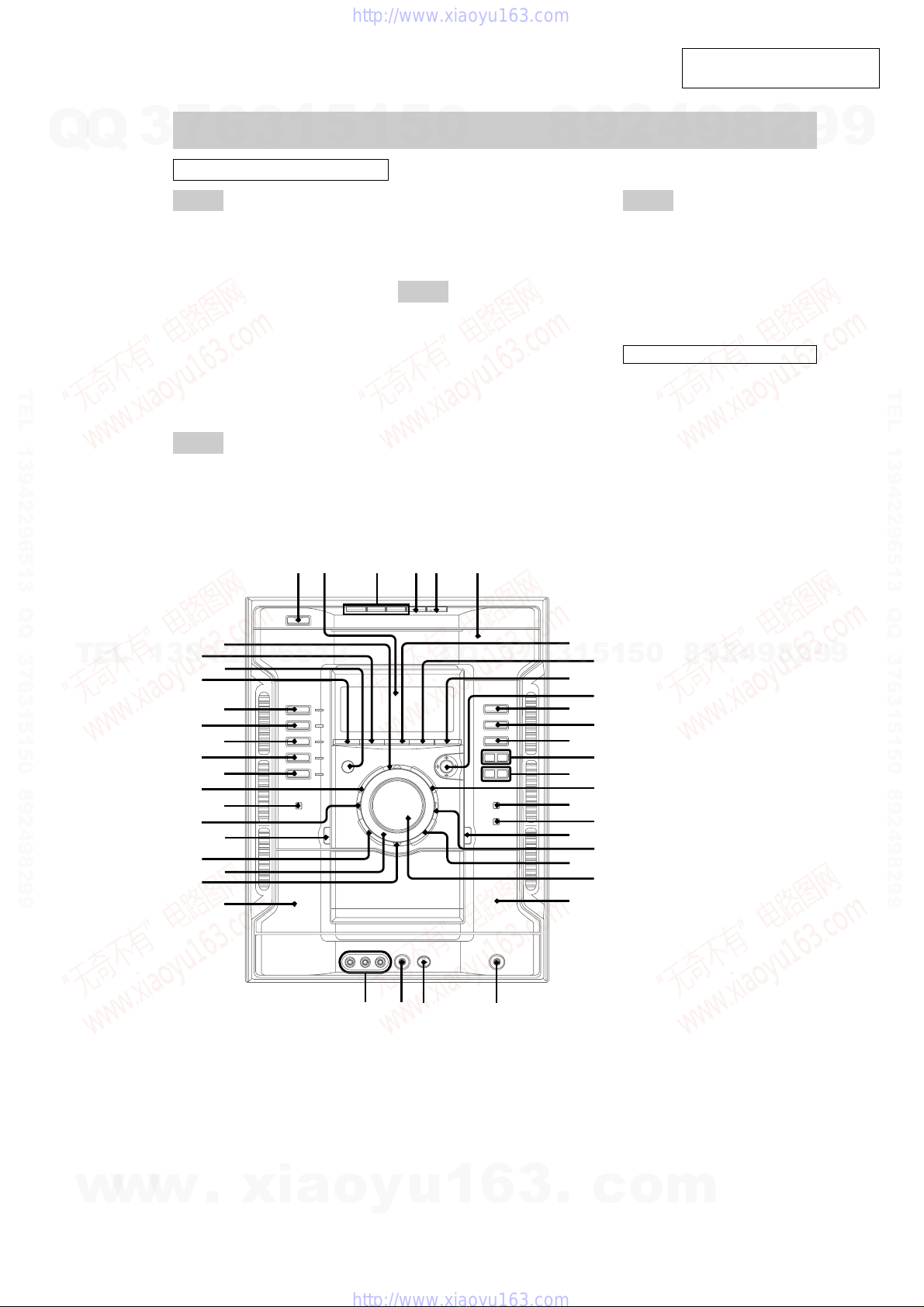
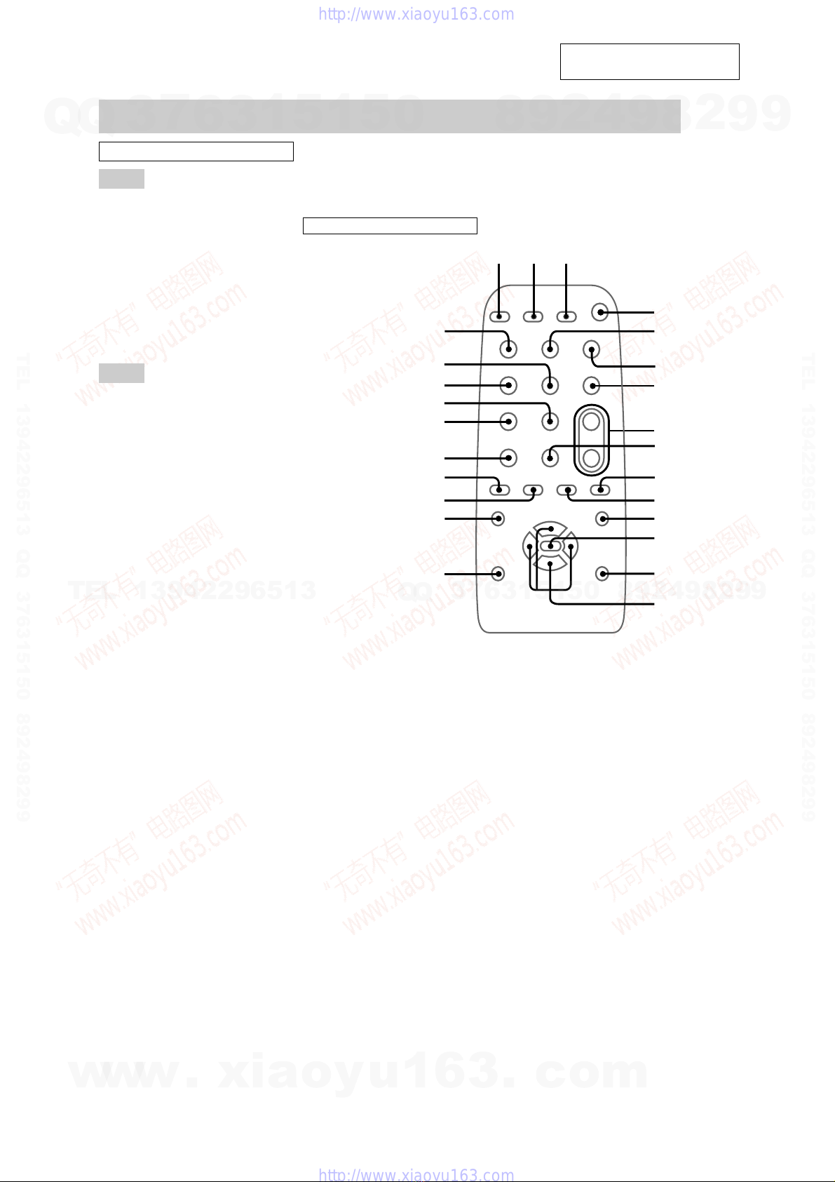
2. GENERAL
Location of Controls ....................................................... 5
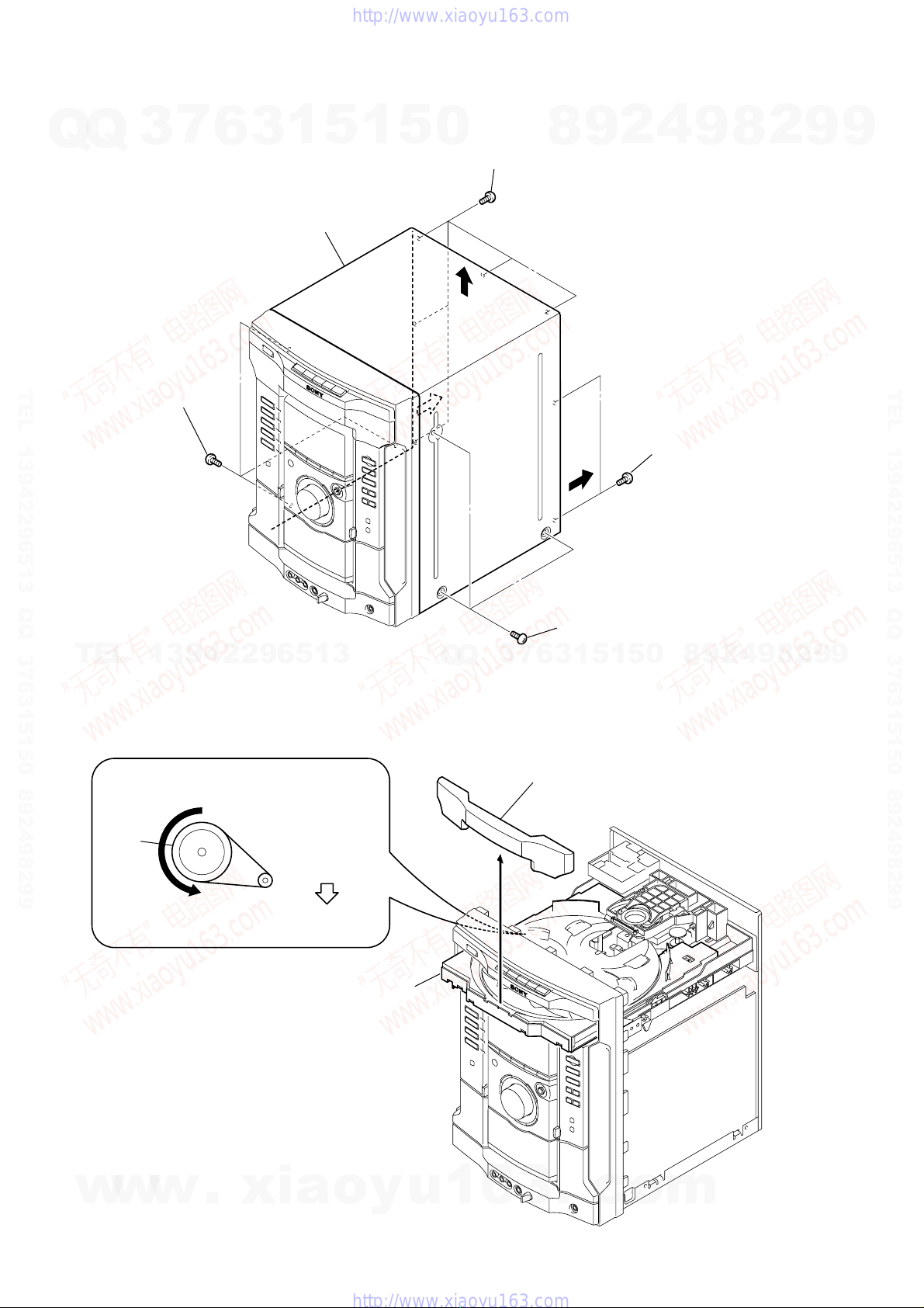
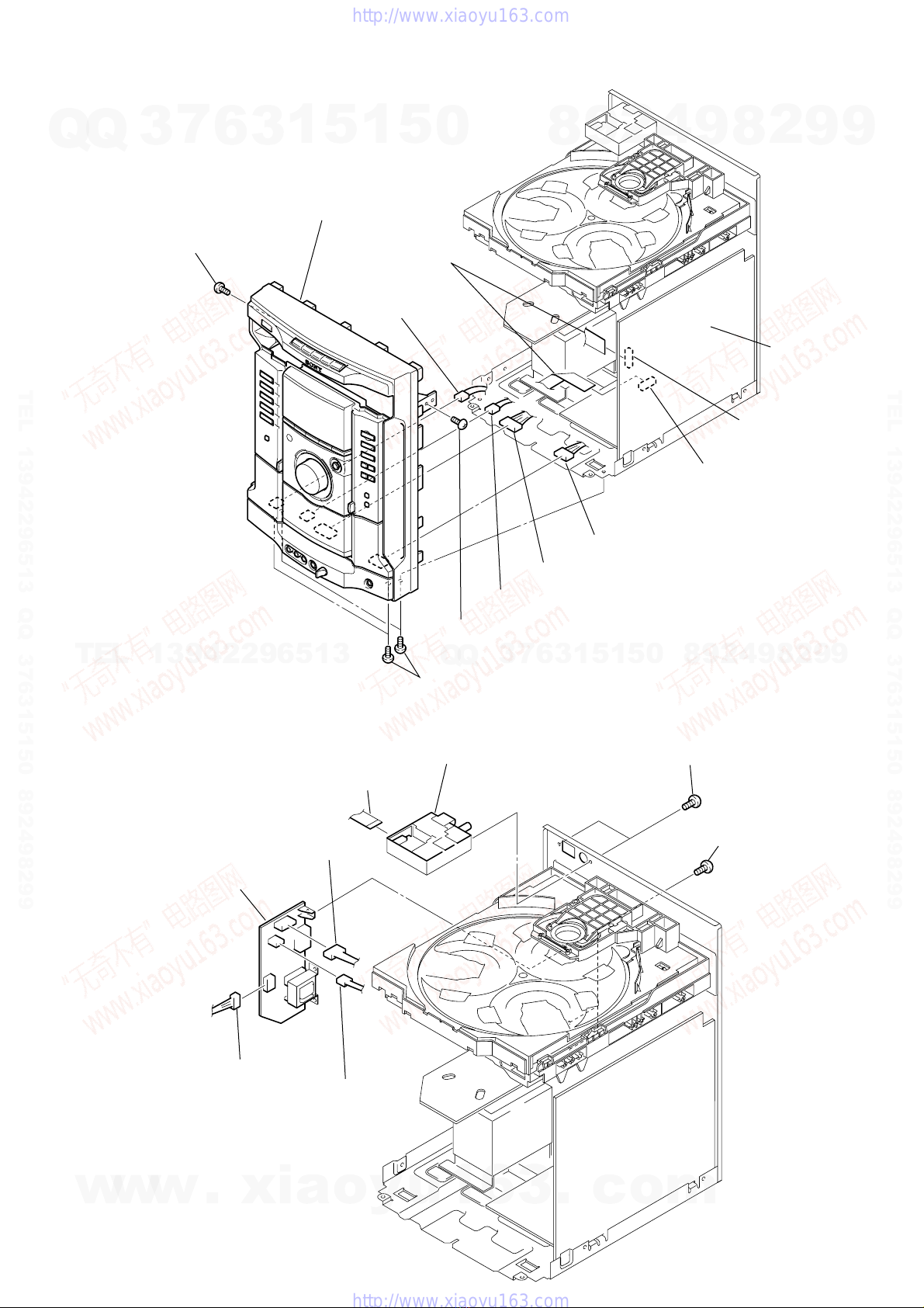
3. DISASSEMBLY
3-1. Case ................................................................................. 8
3-2. Loading (Panel)............................................................... 8
3-3. Front Panel Assy ............................................................. 9
3-4. Tuner Pack, Sub Trans Board ......................................... 9
3-5. CD Mechanism Deck ...................................................... 10
3-6. Game In Board, Tape Mechanism Deck......................... 10
3-7. CD Switch Board, Display Board .................................. 11
3-8. Volume Board.................................................................. 11
3-9. Subwoofer Board, Rear Panel ........................................ 12
3-10. Main Board...................................................................... 12
3-11. Power Amp Board ........................................................... 13
3-12. SW Board, Driver Board................................................. 13
3-13. CD Board, CD Block Assy ............................................. 14
3-14. Sensor Board ................................................................... 14
3-15. Motor (TB) Board ........................................................... 15
3-16. Motor (LD) Board ........................................................... 15
4. TEST MODE.............................................................. 16
5. MECHANICAL ADJUSTMENTS....................... 20
6. ELECTRICAL ADJUSTMENTS
Deck section .................................................................... 20
CD Section ...................................................................... 22
7. DIAGRAMS
7-1. Circuit Board Location ................................................... 26
7-2. Block Diagram –CD Servo Section –........................... 28
Block Diagram –Tuner/Tape Deck Section –............... 29
Block Diagram –Main/Power Section –....................... 30
Block Diagram –Display Section –.............................. 31
7-3. Printed Wiring Board –CD Board –............................. 32
7-4. Schematic Diagram –CD Board –................................ 33
7-5. Printed Wiring Board –CD Mechanism Board –......... 34
7-6. Schematic Diagram –CD Mechanism Board –............ 35
7-7. Printed Wiring Boards –Main Board –......................... 36
7-8. Schematic Diagram –Main Board (1/3) –.................... 37
7-9. Schematic Diagram –Main Board (2/3) –.................... 38
7-10. Schematic Diagram –Main Board (3/3) –.................... 39
7-11. Printed Wiring Boards
–Game In, CD Switch Board –...................................... 40
7-12. Schematic Diagram
–Game In, CD Switch Board –...................................... 41
7-13. Printed Wiring Board –Display Board –...................... 42
7-14. Schematic Diagram –Display Board –......................... 43
7-15. Printed Wiring Board –Power Amp Board –................ 44
7-16. Schematic Diagram –Power Amp Board –.................. 45
7-17. Printed Wiring Board –Subwoofer Board –................. 46
7-18. Schematic Diagram –Subwoofer Board –.................... 47
7-19. Printed Wiring Boards –Trans Board –........................ 48
7-20. Schematic Diagram –Trans Board –............................. 49
7-21. IC Block Diagram ........................................................... 50
7-22. IC Pin Function Description ........................................... 51
8. EXPLODED VIEWS
8-1. Case, Rear Panel Section ................................................ 56
8-2. Front Panel Section ......................................................... 57
8-3. Chassis Section ............................................................... 58
8-4. CD Mechanism Deck Section-1
(CDM74-K6BD47S) ....................................................... 59
8-5. CD Mechanism Deck Section-2
(CDM74-K6BD47S) ....................................................... 60
9. ELECTRICAL PARTS LIST ............................... 61
w
w
w
.
x
i
a
o
y
u
1
6
3
.
c
o
m
Q
Q
3
7
6
3
1
5
1
5
0
9
9
2
8
9
4
2
9
8
T
E
L
1
3
9
4
2
2
9
6
5
1
3
9
9
2
8
9
4
2
9
8
0
5
1
5
1
3
6
7
3
Q
Q
TEL 13942296513 QQ 376315150 892498299
http://www.xiaoyu163.com

4
HCD-GN800
SECTION 1
SERVICING NOTES
NOTES ON HANDLING THE OPTICAL PICK-UP
BLOCK OR BASE UNIT
The laser diode in the optical pick-up block may suffer electro-
static break-down because of the potential difference generated
by the charged electrostatic load, etc. on clothing and the human
body.
During repair, pay attention to electrostatic break-down and also
use the procedure in the printed matter which is included in the
repair parts.
The flexible board is easily damaged and should be handled with
care.
NOTES ON LASER DIODE EMISSION CHECK
The laser beam on this model is concentrated so as to be focused
on the disc reflective surface by the objective lens in the optical
pick-up block. Therefore, when checking the laser diode emis-
sion, observe from more than 30 cm away from the objective lens.
LASER DIODE AND FOCUS SEARCH OPERATION
CHECK
Carry out the “S curve check” in “CD section adjustment” and
check that the S curve waveforms is output three times.
•MODEL IDENTIFICATION
– Back Panel –
MODEL PART No.
E2, E3models 4-244-107-0[]
E51 model 4-244-107-1[]
Mexican model 4-244-107-2[]
Argentina model 4-244-107-3[]
•Abbreviation
E2 : 120 V AC Area in E model
E3 : 240 V AC Area in E model
E51 : Chilean and Peruvian model
PA R T No.
w
w
w
.
x
i
a
o
y
u
1
6
3
.
c
o
m
Q
Q
3
7
6
3
1
5
1
5
0
9
9
2
8
9
4
2
9
8
T
E
L
1
3
9
4
2
2
9
6
5
1
3
9
9
2
8
9
4
2
9
8
0
5
1
5
1
3
6
7
3
Q
Q
TEL 13942296513 QQ 376315150 892498299
http://www.xiaoyu163.com

5
HCD-GN800
SECTION 2
GENERAL
ALBUM+/- qg
AMP MENU rd
CD r;
CD SYNC qj
DECK A wk
DECK B wd
DIRECTION 9
DISC 1~3 3
DISCSKIPEX-CHANGE4
Disc tray 6
DISPLAY ra
Display 2
EDIT9
EFFECT ON/OFFrf
FM MODE 8
GAME eh
GAME EQ ea
GAME INPUT (jacks)wj
GAME MIXING ef
GROOVEed
IR (receptor) rs
ILLUMINATION wl
MD (VIDEO) ej
MIC(jack) wh
MICLEVELwg
MOVIE EQ qh
MUSIC EQ eg
OPEN/CLOSE Z5
P FILEwa
PHONES (jack) wf
PLAY MODE 7
Power illuminatore;
PUSH ENTERq;
REC PAUSE/START qk
REPEAT 8
SURROUND SPEAKER MODE w;
TAPE A/B ek
TUNER/BAND el
TUNER MEMORY 7
VOLUME ws
SYMBOLS
@/1 (power) 1
hH (play)qa
x(stop) qs
X(pause) qd
-.(go backward)qf
> + (go forward) qf
m(rewind) qg
M(fast forward)qg
V/v/B/bq;
AA (Eject A)es
AB (Eject B)ql
ALPHABETICAL ORDER
A - D
M - Q
wk
e
k
wl
e
l
e;
ea
es
eg
ed
ef
ej
eh
r
d
r;
r
a
r
s
rf
wfwgwh
wj
qs
qd
qf
qg
qh
qj
q
l
qk
w;
wa
ws
wd
0
qa
4 5 612 3
7
8
9
Mainunit
E - L
R - Z
This section is extracted from
instruction manual.
w
w
w
.
x
i
a
o
y
u
1
6
3
.
c
o
m
Q
Q
3
7
6
3
1
5
1
5
0
9
9
2
8
9
4
2
9
8
T
E
L
1
3
9
4
2
2
9
6
5
1
3
9
9
2
8
9
4
2
9
8
0
5
1
5
1
3
6
7
3
Q
Q
TEL 13942296513 QQ 376315150 892498299
http://www.xiaoyu163.com

6
HCD-GN800
RemoteControl
4
5
qk
ql
w;
wa
ws
123
wg
wf
wd
qh
qj
qa
qs
qd
qf
7
q;
qg
8
9
6
CD ql
CLEAR 7
CLOCK/TIMER SELECT 2
CLOCK/TIMER SET 3
D.SKIP 9
ENTER qd
EFFECT ON/OFFqf
GAME w;
MD (VIDEO) q;
PRESET - wd
PRESET + wf
PRESET EQ qj
P FILE qh
SURROUND SPEAKER MODE qs
SLEEP 1
TAPE A/B qa
TUNER/BAND qk
TUNING - wa
TUNING + ws
VOL +/- 8
SYMBOLS
@/1 (power) 4
nN (play) wg
X(pause) 5
x(stop) 6
.(go backward)wd
>(go forward) wf
m(rewind) wa
M(fast forward)ws
M/m/</,qg
A - M
P - Z
ALPHABETICAL ORDER
This section is extracted from
instruction manual.
w
w
w
.
x
i
a
o
y
u
1
6
3
.
c
o
m
Q
Q
3
7
6
3
1
5
1
5
0
9
9
2
8
9
4
2
9
8
T
E
L
1
3
9
4
2
2
9
6
5
1
3
9
9
2
8
9
4
2
9
8
0
5
1
5
1
3
6
7
3
Q
Q
TEL 13942296513 QQ 376315150 892498299
http://www.xiaoyu163.com

7
HCD-GN800
• This set can be disassembled in the order shown below.
SECTION 3
DISASSEMBLY
CASE
LOADING (PANEL)
SET
FRONT PANEL ASSY
CD SWITCH BOARD,
DISPLAY BOARD
CD BOARD,
CD BLOCK ASSY
OPTICAL PICK-UP
(KSS-213DCP)
VOLUME BOARD
SW BOARD,
DRIVER BOARD MOTOR (TB) BOARD
CD MECHANISM DECK GAME IN BOARD,
TAPE MECHANISM DECK
TUNER PACK,
SUB TRANS BOARD
MOTOR (LD) BOARD
SENSOR BOARD
SUBWOOFER BOARD
REAR PANEL
MAIN BOARD
POWER AMP BOARD
w
w
w
.
x
i
a
o
y
u
1
6
3
.
c
o
m
Q
Q
3
7
6
3
1
5
1
5
0
9
9
2
8
9
4
2
9
8
T
E
L
1
3
9
4
2
2
9
6
5
1
3
9
9
2
8
9
4
2
9
8
0
5
1
5
1
3
6
7
3
Q
Q
TEL 13942296513 QQ 376315150 892498299
http://www.xiaoyu163.com

8
HCD-GN800
Note: Follow the disassembly procedure in the numerical order given.
3-1. CASE
3-2. LOADING (PANEL)
1
Three screws
(case 3 TP2)
2
Five screws
(+BVTT3 x 6)
6
Case
5
4
1
Three screws
(case 3 TP2)
3
Two screws
(+BVTT3 x 6
)
CD mechanismdeck (CDM74-K6BD47S)
1
Turn the pulley to the arrow direction.
Front side
Pulley
4
Loading (panel)
3
2
Pull out disc tray
w
w
w
.
x
i
a
o
y
u
1
6
3
.
c
o
m
Q
Q
3
7
6
3
1
5
1
5
0
9
9
2
8
9
4
2
9
8
T
E
L
1
3
9
4
2
2
9
6
5
1
3
9
9
2
8
9
4
2
9
8
0
5
1
5
1
3
6
7
3
Q
Q
TEL 13942296513 QQ 376315150 892498299
http://www.xiaoyu163.com

9
HCD-GN800
3-3. FRONT PANEL ASSY
3-4.TUNER PACK, SUBTRANS BOARD
3
Screw (BVTP3 x 10)
2
Four screws (BVTP3 x 10)
8
Front panel ASSY
5
From CN606 on Game in board
4
From deck B head
CN402
CN304
6
From deck A head
7
From CN607 on
Game in board
1
Two wires
(flat type)
3
Screw (BVTP3 x 10)
MAIN boar
d
8
Sub trans board
4
CN971
5
CN974
6
CN976
1
Wire (flat type)
(11 core)
3
Tuner pack
2
Two screw (BVTP3 x 10)
7
Three screws
(BVTP3 x 10)
w
w
w
.
x
i
a
o
y
u
1
6
3
.
c
o
m
Q
Q
3
7
6
3
1
5
1
5
0
9
9
2
8
9
4
2
9
8
T
E
L
1
3
9
4
2
2
9
6
5
1
3
9
9
2
8
9
4
2
9
8
0
5
1
5
1
3
6
7
3
Q
Q
TEL 13942296513 QQ 376315150 892498299
http://www.xiaoyu163.com

10
HCD-GN800
3-5. CD MECHANISM DECK
3-6. GAME IN BOARD,TAPE MECHANISM DECK
4
CD mechanism deck
2
Wire (flat type) (31 core)
1
Two screws (BVTP3 x 10
)
3
CN701
MAIN board
CN201
8
Tape mechanism deck
7
Three screws
(+BVTP2.6 x 8)
Shield plate (GHX)
2
Screw (+PTT2 x 4)
2
Screw (+PTT2 x 4)
4
Two screws (+BVTP2.6 x 8)
3
Two screws
(+BVTP2.6 x 8
)
5
Two screws
(+BVTP2.6 x 8)
6
GAME IN board
1
Knob (MIC)
w
w
w
.
x
i
a
o
y
u
1
6
3
.
c
o
m
Q
Q
3
7
6
3
1
5
1
5
0
9
9
2
8
9
4
2
9
8
T
E
L
1
3
9
4
2
2
9
6
5
1
3
9
9
2
8
9
4
2
9
8
0
5
1
5
1
3
6
7
3
Q
Q
TEL 13942296513 QQ 376315150 892498299
http://www.xiaoyu163.com

11
HCD-GN800
3-7. CD SWITCH BOARD, DISPLAY BOARD
3-8.VOLUME BOARD
1
Six screws
(+BVTP2.6 x 8)
4
Five screws
(+BVTP2.6 x 8
)
3
Wire (flat type) (17 core)
from CN604
5
DISPLAY board
4
Five screws
(+BVTP2.6 x 8)
2
CD SWITCH board
1
Knob (VOL)
5
VOLUME board
3
Three screws
(+BVTP2.6 x 8)
3
Three screws
(+BVTP2.6 x 8
)
4
Four claws
2
Hexagonal nut
w
w
w
.
x
i
a
o
y
u
1
6
3
.
c
o
m
Q
Q
3
7
6
3
1
5
1
5
0
9
9
2
8
9
4
2
9
8
T
E
L
1
3
9
4
2
2
9
6
5
1
3
9
9
2
8
9
4
2
9
8
0
5
1
5
1
3
6
7
3
Q
Q
TEL 13942296513 QQ 376315150 892498299
http://www.xiaoyu163.com

12
HCD-GN800
3-9. SUBWOOFER BOARD, REAR PANEL
3-10. MAIN BOARD
3
Three screws
(+BVTP3 x 10
)
2
Two screws
(+BVTP3 x 10
)
1
Two screws
(+BVTT3 x 6)
4
Three screws
(+BVTP3 x 10)
5
Connector
CN851
MAIN board
qd
Rear panel
with fan
0
Screw
(+BVTP3 x 10)
6
Connector
8
Connector
CN303
CN305
7
Connector
qs
SUBWOOFER board
qa
Bracket (IC)
9
Two screws
(+BVTP3 x 16)
CN1803
3
Two screws
(+BVTP3 x 10)
2
Screw
(+BVTP3 x 10)
1
Connector
6
MAIN boar
d
MAIN board
(CN901, 902)
POWER AMP board
(CN503, 504)
5
4
CN998
TRAN board
w
w
w
.
x
i
a
o
y
u
1
6
3
.
c
o
m
Q
Q
3
7
6
3
1
5
1
5
0
9
9
2
8
9
4
2
9
8
T
E
L
1
3
9
4
2
2
9
6
5
1
3
9
9
2
8
9
4
2
9
8
0
5
1
5
1
3
6
7
3
Q
Q
TEL 13942296513 QQ 376315150 892498299
http://www.xiaoyu163.com

13
HCD-GN800
3-11. POWER AMP BOARD
2
Two screws
(+BVTP3 x 10)
3
Bracket (HS)
6
Two screws
(+BVTP3 x 10)
4
Two screws
(+BVTP3 x 10)
5
Three screws
(+BVTP3 x 10)
7
POWER AMP boar
d
1
Connector
from CN997
3-12. SW BOARD, DRIVER BOARD
6
DRIVER boar
d
2
SW board
3
CN704
4
CN703
7
CN702 (flat type)
5
Two
screws
(+BTTP (M2.6))
1
Screw
(+BTTP (M2.6))
w
w
w
.
x
i
a
o
y
u
1
6
3
.
c
o
m
Q
Q
3
7
6
3
1
5
1
5
0
9
9
2
8
9
4
2
9
8
T
E
L
1
3
9
4
2
2
9
6
5
1
3
9
9
2
8
9
4
2
9
8
0
5
1
5
1
3
6
7
3
Q
Q
TEL 13942296513 QQ 376315150 892498299
http://www.xiaoyu163.com

14
HCD-GN800
3-13. CD BOARD, CD BLOCK ASSY
3-14. SENSOR BOARD
qa
5
Two
coil springs
(insulator)
9
Two
coil springs
(insulator)
6
Two
insulators
0
Two
insulators
qs
Screw (+BTP 2.6x 8)
7
Two screws
(BVTT M2.6)
2
Holder (213) ASSY
8
Two stoppers (BU)
qd
Remove the four solderings of motor.
qf
CN708 (flat type)
qg
CD board
qh
CD block ASSY
3
Floating
screw
(+PTPWH M2.6)
1
Floating
screw
(+PTPWH M2.6)
4
Two floating
screws
(+PTPWH M2.6)
2
Tray
3
Belt (table)
5
Pulley (table)
8
Screw
(+BTTP (M2.6))
9
SENSOR board
7
Gear (geneva)
0
CN731
1
Floating
screw
(+PTPWH M2.6)
6
Floating
screw
(+PTPWH M2.6)
4
Foating
screw
(+PTPWH M2.6)
w
w
w
.
x
i
a
o
y
u
1
6
3
.
c
o
m
Q
Q
3
7
6
3
1
5
1
5
0
9
9
2
8
9
4
2
9
8
T
E
L
1
3
9
4
2
2
9
6
5
1
3
9
9
2
8
9
4
2
9
8
0
5
1
5
1
3
6
7
3
Q
Q
TEL 13942296513 QQ 376315150 892498299
http://www.xiaoyu163.com

15
HCD-GN800
3-15. MOTOR (TB) BOARD
3-16. MOTOR (LD) BOARD
5
Remove the two solderings of motor.
4
MOTOR (TB) board
2
CN742 (flat type)
6
Table motor ASSY (M741)
3
Two
screws
(+BTTP (M2.6))
1
4
Remove the two solderings of motor.
3
MOTOR (LD) board
1
Belt (loading)
5
Loading motor ASSY (M751)
2
Two
screws
(+BTTP (M2.6))
w
w
w
.
x
i
a
o
y
u
1
6
3
.
c
o
m
Q
Q
3
7
6
3
1
5
1
5
0
9
9
2
8
9
4
2
9
8
T
E
L
1
3
9
4
2
2
9
6
5
1
3
9
9
2
8
9
4
2
9
8
0
5
1
5
1
3
6
7
3
Q
Q
TEL 13942296513 QQ 376315150 892498299
http://www.xiaoyu163.com

16
HCD-GN800 SECTION 4
TEST MODE
[GCTEST MODE]
• This mode is used to check the fluorescent indicator tube, LED,
model, destination, software version, volume, key and VACS
level.
Procedure:
1. Press xbutton, [AMP MENU]button and [DISC 2] button
simultaneously.
2. All LEDs and segments in fluorescent indicator tube are lighted
up.
3. When you want to enter the software version display mode,
press[DISC 1] button. The model and destination are displayed.
4. Each time [DISC 1] button is pressed, the display changes from
MC version, GC version, CD version, CDDM version, CDMA
version,CDMB version, BDA version,BDB version,ST version,
TA version,TM versionand TC version in thisorder,and returns
to the MC version display.
5. When [DISC 3] button is pressed while the version numbers
are being displayed except model and destination, the date of
the software creation appear. When [DISC 3] button is pressed
again, the display returns to the software version display. When
[DISC 1] buttonis pressed whilethe date ofthe software creation
is being displayed, the date of the software creation is displayed
in the same order of software version display.
6. Press [DISC 2] button, the key check mode is activated.
7. In the key check mode, the fluorescent indicator tube displays
“K 0 V 0”.
Each time a button is pressed, “K” value increases. However,
once a button has been pressed, it is no longer taken into account.
“V” value increases in the manner of 0,1, 2, 3 ... if [VOLUME]
knob is turned clockwise, or it decreases in the manner of 0, 9,
8,7 ... if [VOLUME] knob is turned counter-clockwise.
8. When [DISC 3] button is pressed after all LEDs and segments
in fluorescent indicator tube light up, the fluorescent indicator
tube displays “VACS A + B”. A isVACS level which is trigger
bysignal level while B isVACSlevel whichistrigger by thermal.
Total VACS value would be the sum of A and B.
9. When [DISC SKIP/EX-CHANGE] button is pressed after all
LEDs and segments in fluorescent indicator tube light up,
alternate segments in fluorescent indicator tube would light up.
If you press [DISC SKIP/EX-CHANGE] button again, another
half of alternate segments in fluorescent indicator tube would
light up. Pressing [DISC SKIP/EX-CHANGE] button again
would case all segments lights up.
10. To release this mode, press three buttons in the same manner as
step 1, or disconnect the power cord.
[MC TEST MODE]
• This mode is used to check operations of the respective sections
of Amplifier, Tuner, and Tape.
Procedure:
* To enter MC Test Mode
1. Press xbutton, [AMP MENU] button and [DISC 3] button
simultaneously.
2. The TAPE A and TAPE B segments flash on the fluorescent
indicator tube. The function is changed toVIDEO.
* Check of Amplifier
1. When Vbutton is pressed, GEQ increases to its maximum and
a message “GEQ MAX” appears on the fluorescent indicator
tube.
2. When vbutton is pressed, GEQ decreases to its minimum and
a message “GEQ MIN” appears on the fluorescent indicator
tube.
3. When Bbutton or bbutton is pressed, GEQ is set to flat and
a message “GEQ FLAT” appears on the fluorescent indicator
tube.
4. When the [VOLUME] knob is turned clockwise even slightly,
the sound volume increases to its maximum and a message
“VOLUME MAX” appears for two seconds, then the display
returns to the original display.
5. When the [VOLUME] knob is turned counter-clockwise even
slightly, the sound volume decreases to its minimum and a
message “VOLUME MIN” appears for two seconds, then the
display returns to the original display.
* Check of clock frequency
1. To check the frequency of clock used to run the clock of the
system, the clock output is available at IC501 pin ek (CLOCK-
OUT) on the MAIN board during MC test mode.
2. The frequency is 32.768 kHz.
* Tape function
1. When a tape is inserted in Deck B and recording is started, the
function is changed toVIDEO automatically.When [CD SYNC]
button is pressed during recording in function,ALC (Automatic
Logic Control) is turned on.
2. After recording is stopped by pressing xbutton, press m
button will change the function to TAPE B and rewind Tape B
until the recording start position and playback of Tape B is
started. If the [REC PAUSE/ START] button is pressed for a
pause and pressed again to resume recording during recording
time, when tape deck B is rewind, tape deck B will be rewind
until the position where the pause is applied.
* AMS Test Mode
1. Select the function “TAPE A”or “TAPE B”.
2. Select Loop or Relay direction mode by pressing the
[DIRECTION] button. Insert a test tape AMS-110A or AMS-
120 to selected tape deck.
3. Press the [AMP MENU] button to enter the AMS test mode.
4. After the test tape is rewind to the beginning of the tape, the
AMS+ is checked, and the mechanism is shut off after detecting
the AMS signal twice.
5. Then the AMS- is checked and the mechanism is shut off after
detecting the AMS signal twice.
6. When the check is complete, a message of either OK or NG
appears.
* To release MC Test mode.
1. To release this mode, press ?/1 button.
2. The cold reset is enforced at the same time.
w
w
w
.
x
i
a
o
y
u
1
6
3
.
c
o
m
Q
Q
3
7
6
3
1
5
1
5
0
9
9
2
8
9
4
2
9
8
T
E
L
1
3
9
4
2
2
9
6
5
1
3
9
9
2
8
9
4
2
9
8
0
5
1
5
1
3
6
7
3
Q
Q
TEL 13942296513 QQ 376315150 892498299
http://www.xiaoyu163.com

17
HCD-GN800
[COLD RESET]
•The cold reset clears all data including preset data stored in the
RAM to initial conditions. Execute this mode when returning
the set to the customer.
Procedure:
1. Press xbutton, [AMP MENU] button, and ?/1 button
simultaneously.
2. The fluorescent indicator tube becomes blank for a while, and
the set is reset.
[VACS ON/OFF]
•This mode is used to switch ON and OFF the VACS (Variable
Attenuation Control System).
Procedure:
1. Press ?/1 button to turn the set ON.
2. Press [AMP MENU] button and [GAME MIXING] button
simultaneously. The message “VACS OFF”or “VACS ON”
appears.
[TUNER STEP CHANGE]
•The step interval ofAM channels can be toggled between 9 kHz
and 10 kHz.
Procedure:
1. Press ?/1 button to turn the set ON.
2. Press [TUNER/BAND] button to select the “AM”.
3. Press ?/1 button to turn the set OFF.
4. Press [AMP MENU] button and ?/1 button simultaneously.
The system will turn ON automatically. The message “AM 9k
STEP”or AM 10k STEP”appears and thus the channel step is
changed.
[CD SERVICE MODE]
•This mode let you move the CD sled motor freely. Use this mode
when you want to clean the optical pick-up.
Procedure:
1. Press ?/1 button to turn the set ON.
2. Select CD function.
3. Press x, [AMP MENU] button,and
Z
OPEN/CLOSE
button
simultaneously.
4. The CD service mode is activated. The message “SERVICE
MODE”appears.
5. With the CD in stop status, press Mbutton to move the
opticalpick-up to outside track,orpress mbuttonto move
to inside track. The message “SLED OUT”or “SLED IN”
appears.
6. To release this mode, press ?/1 button.
[AGING MODE]
This mode can be used for operation check of CD section.
•If an error occurs, the aging operation would stops and the status
is displayed.
•If there are no error occurs, the aging operation would continues
repeatedly.
Procedure:
1. Press ?/1 button to turn the set ON
2. Select CD function.
3. Load three discs on the disc tray.
4. Press [PLAY MODE] button to select the “ALL DISCS”mode,
andpress the [REPEAT] button to select “REPEAT OFF”mode.
5. Press xbutton, [AMP MENU] button, and [DISC SKIP/ EX-
CHANGE] button simultaneously.
6. Aging operation is started.
7. To release this mode, press ?/1 button or disconnect the
power cord to turn the power OFF.
Aging mode sequence:
Start (from disc 1)
Disc chucking
TOC reading
Play first track for 2 seconds
Play last track for 2 seconds
EX-CHANGE open/close
Open the disc tray
Disc skip
Close the disk tray
Change the next disc.
w
w
w
.
x
i
a
o
y
u
1
6
3
.
c
o
m
Q
Q
3
7
6
3
1
5
1
5
0
9
9
2
8
9
4
2
9
8
T
E
L
1
3
9
4
2
2
9
6
5
1
3
9
9
2
8
9
4
2
9
8
0
5
1
5
1
3
6
7
3
Q
Q
TEL 13942296513 QQ 376315150 892498299
http://www.xiaoyu163.com

18
HCD-GN800
•Display when an error occurred (CD Error Code Mode)
Procedure:
1. Press xbutton, [AMP MENU] button and [DISC 1] button
simultaneously to enter the error code display mode.
2. The fluorescent indicator tubedisplays the number oftotal error.
3. Each time Mbutton or mbutton is pressed, display
change as below
Display of total error
M+
Button
–m
Button
Display of Mechanical errors
M+
Button
–m
Button
Display of no disc errors
4. To clear the error record, operate the cold reset. (Refer to the
“MC COLD RESET”)
5. To release this mode, press the ?/1 button or disconnect the
power plug to turn the power OFF.
1) Display of total error
EMC**: The number of mechanical errors.
EDC**: The number of no disc errors after chucking the disc.
2) Display of mechanical errors
M*: The number of mechanical error (“00”is latest one)
(Press >button or
.
button to display next error)
$$: Not used
%%: Loading related error (Second figure is not used)
D: Stop by the problem other than mechanical problem while
closing.
E: Stop by the problem other than mechanical problem while
opening.
C: Stop by the problem other than mechanical problem while
chucking up.
F: Stop by the problem other than mechanical problem while
chucking down.
&&: Emerging error
01: Stop while chucking up.
02: Stop while chucking up.
03: Time-out of EX-CHANGE open.
05: Time-out of EX-CHANGE close.
##: Not used
3) Display of no disc errors
D*: The number of mechanical error (“00”is latest one)
(Press
>
button or
.
button to display next error)
$$: Error type
01: Focus error
02: GFS error
03: Setup error
%%: Not used
&&:
00: No disc judgment without chucking retry.
01: No disc judgment after chucking retry.
##: The state when judged as no disc
01: Stop
02: Setup
03: TOC reading
04: Access
05: Playback
06: Pause
07: Manual search (Play)
08: Manual search (Pause)
[CD REPEAT 5 LIMIT OFF MODE]
•The number of repeat for CD playback is 5 times when the repeat
mode is “REPEAT ALL”. This mode enables CD to repeat
playback for limitless times.
Procedure:
1. Press ?/1 button to turn the set ON.
2. Select CD function.
3. Press xbutton, [REPEAT] button and [CD] button
simultaneously to enter the CD repeat 5 limit off mode and the
fluorescent indicator tube displays “LIMIT OFF”.
3. To release this mode, operate the cold reset. (Refer to the “MC
COLD RESET”)
[CD SHIP MODE (WITH MEMORY CLEAR)]
•This mode moves the optical pick-up to the position durable to
vibration and clears all data including preset data stored in the
RAM to initial conditions. Use this mode when returning the
set to the customer after repair.
Procedure:
1. Press ?/1 button to turn the set ON.
2. Select CD function.
3. Press xbutton, [AMP MENU] button and [GAME] button
simultaneously. The set will power off automatically.
4. After the “STANDBY”blinking display finish, a message
“LOCK”is displayed on the fluorescent indicator tube and the
CD ship mode is set.
Display
EMC**EDC**
Display
M*$$%%&&##00
Display
D*$$%%&&##00
w
w
w
.
x
i
a
o
y
u
1
6
3
.
c
o
m
Q
Q
3
7
6
3
1
5
1
5
0
9
9
2
8
9
4
2
9
8
T
E
L
1
3
9
4
2
2
9
6
5
1
3
9
9
2
8
9
4
2
9
8
0
5
1
5
1
3
6
7
3
Q
Q
TEL 13942296513 QQ 376315150 892498299
http://www.xiaoyu163.com

19
HCD-GN800
[CD SHIP MODE (WITHOUT MEMORY CLEAR)]
•This mode moves the optical pick-up to the position durable to
vibration. Use this mode when returning the set to the customer
after repair.
Procedure:
1. Press ?/1 button to turn the set ON.
2. Select CD function.
3. Press [CD] button and ?/1 button simultaneously. The set
will power off automatically.
4. After the “STANDBY”blinking display finish, a message
“LOCK”is displayed on the fluorescent indicator tube and the
CD ship mode is set.
[CD POWER MANAGE]
•This mode let you switch on or off power supply to the BU
during TUNER function.
•When CD POWER is set to OFF, the power supply to the BU is
cut off during TUNER function. It will increase the time taken
to access CD when function change from TUNER to CD but it
will improve tuner reception.
•When CD POWER is set to ON, the power supply to the BU is
not cut off duringTUNER function. It will reduce the time taken
to access CD when function change from TUNER to CD but it
will decrease tuner reception performance.
Procedure:
1. Press ?/1 button to turn the set ON.
2. Select CD function.
3. Press ?/1 button to turn the set OFF.
4. Press xbutton and ?/1 button simultaneously. The set will
power on automatically.
5. The message “CD POWER ON”or “CD POWER OFF”will
be displayed on the fluorescent indicator tube.
[CDTRAY LOCK MODE]
•This mode let you lock the disc trays. When this mode is
activated, the disc tray will not open when
Z
OPEN/CLOSE
button or [DISC SKIP/EX-CHANGE] button is pressed. The
message “LOCKED”will be displayed in the will be displayed
on the fluorescent indicator tube.
Procedure:
1. Press ?/1 button to turn the set ON.
2. Select CD function.
3. Press xbutton and
ZOPEN/CLOSE
button simultaneously
and hold down until “LOCKED”or “UNLOCKED”displayed
on the fluorescent indicator tube (around 5 seconds).
[MD/VIDEO SWITCHING]
•This mode let you switch from MD to VIDEO and vice-versa.
Procedure:
1. Press ?/1 button to turn the set ON.
2. Select MD function.
3. Press [MD $VIDEO%] button and ?/1 button simultaneously.
The function will change to VIDEO. Press the same buttons
again to change from VIDEO to MD.
w
w
w
.
x
i
a
o
y
u
1
6
3
.
c
o
m
Q
Q
3
7
6
3
1
5
1
5
0
9
9
2
8
9
4
2
9
8
T
E
L
1
3
9
4
2
2
9
6
5
1
3
9
9
2
8
9
4
2
9
8
0
5
1
5
1
3
6
7
3
Q
Q
TEL 13942296513 QQ 376315150 892498299
http://www.xiaoyu163.com

20
HCD-GN800
SECTION 5
MECHANICAL ADJUSTMENTS
SECTION 6
ELECTRICAL ADJUSTMENTS
Precaution
1. Clean the following parts with a denatured alcohol-moistened
swab:
record/playback heads pinch rollers
erase head rubber belts
capstan idlers
2. Demagnetize the record/playback head with a head
demagnetizer.
3. Do not use a magnetized screwdriver for the adjustments.
4. After the adjustments, apply suitable locking compound to the
parts adjusted.
5. The adjustments should be performed with the rated power
supply voltage unless otherwise noted.
Torque Measurement
3.06 N • m to 6.96 N • m
31 to 71 g • cm
(0.43 – 0.98 oz • inch)
0.19 N • m to 0.58 N • m
2 to 6 g • cm
(0.02 – 0.08 oz • inch)
3.06 N • m to 6.96 N • m
31 to 71 g • cm
(0.43 – 0.98 oz • inch)
0.19 N • m to 0.58 N • m
2 to 6 g • cm
(0.02 – 0.08 oz • inch)
6.96 N • m to 14.02 N • m
71 to 143 g • cm
(0.98 – 1.99 oz • inch)
9.80 N • m
100 g or more
(3.53 oz or more)
9.80 N • m
100 g or more
(3.53 oz or more)
Mode Torque meter
CQ-102C
CQ-102C
CQ-102RC
CQ-102RC
CQ-201B
CQ-403A
CQ-403R
Meter reading
FWD
FWD
back tension
REV
REV
back tension
FF/REW
FWD tension
REV tension
0 dB=0.775 V
DECK SECTION
1. Demagnetize the record/playback head with a head
demagnetizer.
2. Do not use a magnetized screwdriver for the adjustments.
3. After the adjustments, apply suitable locking compound to the
parts adjust.
4. The adjustments should be performed with the rated power
supply voltage unless otherwise noted.
5. The adjustments should be performed in the order given in this
service manual. (As a general rule, playback circuit adjustment
should be completed before performing recording circuit
adjustment.)
6. The adjustments should be performed for both L-CH and R-
CH.
7. Switches and controls should be set as follows unless otherwise
specified.
•Test Tape
RECORD/PLAYBACK HEAD AZIMUTH ADJUST-
MENT
DECK A DECK B
Note: Perform this adjustments for both decks
Procedure:
1. Mode: Playback
Tape Signal Used for
P-4-A100 10 kHz, –10 dB Azimuth Adjustment
set
MAIN board
CN301
Pin
1
(L-CH)
Pin
3
(R-CH)
MAIN board
CN301
Pin
2
(GND)
+
–
level meter
test tape
P-4-A100
(10 kHz, –10 dB)
w
w
w
.
x
i
a
o
y
u
1
6
3
.
c
o
m
Q
Q
3
7
6
3
1
5
1
5
0
9
9
2
8
9
4
2
9
8
T
E
L
1
3
9
4
2
2
9
6
5
1
3
9
9
2
8
9
4
2
9
8
0
5
1
5
1
3
6
7
3
Q
Q
TEL 13942296513 QQ 376315150 892498299
http://www.xiaoyu163.com
Other manuals for HCD-GN800
1
Table of contents
Other Sony Stereo System manuals

Sony
Sony CMT-CP100 User manual

Sony
Sony RDH-GTK33iP User manual

Sony
Sony HCD-EC55 - Receiver System User manual

Sony
Sony CMT-V10iP User manual

Sony
Sony LBT-D260 User manual

Sony
Sony HCD-D790 User manual

Sony
Sony CMT-SP55TC User manual

Sony
Sony SRS-X9 User manual

Sony
Sony 4548736019614 User manual

Sony
Sony WX-GT90BT User manual

Sony
Sony HCD-CPZ1 User manual

Sony
Sony HCD-GNX780 User manual

Sony
Sony MHC-DX6AV User manual

Sony
Sony ZS-PS30CP User manual

Sony
Sony CHC-TB20 User manual

Sony
Sony CHC-CL1 - Compact Hi Fi Component System User manual

Sony
Sony HTC-W555 User manual

Sony
Sony SRS-X33 User manual

Sony
Sony ICF-C11iP User manual

Sony
Sony MHC-DX30 User manual