Sony HCD-HP7 - Hi Fi Components User manual

HCD-HP7
US Model
Canadian Model
AEP Model
UK Model
E Model
Australian Model
SERVICE MANUAL
MICRO HI-FI COMPONENT SYSTEM
Sony Corporation
Home Audio Company
Published by Sony Engineering Corporation
9-877-349-02
2003K16-1
© 2003.11
HCD-HP7 is the Amplifier, CD player, Tape
Deck and Tuner section in CMT-HP7.
SPECIFICATIONS
Ver 1.1 2003. 11
CD player section
System Compact disc and digital
audio system
LaserSemiconductor laser
(λ=780 nm)
Emission duration:
continuous
Frequency response 2 Hz – 20 kHz (±0.5 dB)
Wavelength 780 – 790 nm
Signal-to-noise ratio More than 90 dB
Dynamic range More than 90 dB
Tape deck section
Recording system 4-track 2-channel, stereo
Frequency response 50 – 13,000 Hz (±3 dB),
using Sony TYPE I
cassettes
Main unit
AUDIO POWER SPECIFICATIONS
POWER OUTPUT AND TOTAL HARMONIC
DISTORTION:
With 6 ohm loads, both channels driven, from
120 – 10,000 Hz: rated 60 watts per channel
minimum RMS power, with no more than 10%
total harmonic distortion from 250 milliwatts to
rated output.
Amplifier section
North American model:
Continuous RMS power output (reference):
60 + 60 watts (6 ohms at 1
kHz, 10% THD)
Total harmonic distortion less than0.7%(6 ohmsat 1
kHz, 30 W)
European and Russian models:
DIN power output (rated): 60 + 60 watts (6 ohms at 1
kHz, DIN)
Continuous RMS power output (reference):
60 + 60 watts (6 ohms at 1
kHz, 10% THD)
Music power output (reference):
120 + 120 watts (6 ohms at
1 kHz, 10% THD)
Other models:
The following measured at AC 120, 127, 220, 240 V
50/60 Hz
DIN power output (rated): 60 + 60 watts (6 ohms at 1
kHz, DIN)
Continuous RMS power output (reference):
60 + 60 watts (6 ohms at 1
kHz, 10% THD)
Inputs
MD IN (phono jacks): Sensitivity 250 mV,
impedance 47 kilohms
Outputs
PHONES (stereo minijack):
accepts headphones of 8
ohms or more
OPTICAL CD DIGITAL OUT (Supported sampling
frequency: 44.1 kHz)
SPEAKER: accepts impedance of 6 to
16 ohms.
Model Name Using Similar Mechanism NEW
CD CD Mechanism Type CDM69CH-K6BD71C
Section Base Unit Name BU-K6BD71C
Optical Pick-up Name KSM-213D
TAPE Model Name Using Similar Mechanism HCD-EP515
Section Tape Transport Mechanism Type CMAL1Z234A

2
HCD-HP7
SAFETY-RELATED COMPONENTWARNING!!
COMPONENTS IDENTIFIED BY MARK 0OR DOTTED LINEWITH
MARK 0ON THE SCHEMATIC DIAGRAMS AND INTHE PARTS
LIST ARE CRITICAL TO SAFE OPERATION. REPLACE THESE
COMPONENTS WITH SONY PARTS WHOSE PART NUMBERS
APPEAR AS SHOWN IN THIS MANUAL OR IN SUPPLEMENTS
PUBLISHED BY SONY.
ATTENTION AU COMPOSANT AYANT RAPPORT
À LA SÉCURITÉ!
LES COMPOSANTS IDENTIFÉS PAR UNE MARQUE 0SUR LES
DIAGRAMMES SCHÉMATIQUES ET LA LISTE DES PIÈCES SONT
CRITIQUES POUR LA SÉCURITÉ DE FONCTIONNEMENT. NE
REMPLACER CES COMPOSANTS QUE PAR DES PIÈSES SONY
DONT LES NUMÉROS SONT DONNÉS DANS CE MANUEL OU
DANS LES SUPPÉMENTS PUBLIÉS PAR SONY.
General
Power requirements
North American model: 120 V AC, 60 Hz
European and Russian models:
230 V AC, 50/60 Hz
Australian model: 230 – 240 V AC, 50/60 Hz
Mexican model: 120 V AC, 60 Hz
Other models: 120 V, 220 V or 230 – 240
V AC, 50/60 Hz
Adjustable with voltage
selector
Power consumption
European and Russian models:
100 watts
0.35 watts (at the Power
Saving Mode)
Other models: 100 watts
Dimensions (w/h/d) Approx. 199 252 400
mm
Mass Approx. 7.0 kg
Supplied accessories: Remote Commander (1)
Batteries (2)
AM loop antenna (1)
FM lead antenna (1)
Speaker pads (8)
Design and specifications are subject to change
without notice.
Tuner section
FM stereo, FM/AM superheterodyne tuner
FM tuner section
Tuning range
Russian model: 65.0 – 74.0 MHz
(There is no stereo effect)
87.5 – 108.0 MHz
Other models: 87.5 – 108.0 MHz
Antenna FM lead antenna
Antenna terminals 75 ohms unbalanced
Intermediate frequency 10.7 MHz
AM tuner section
Tuning range
Pan-American model: 530 – 1,710 kHz
(with the tuning interval
set at 10 kHz)
531 – 1,710 kHz
(with the tuning interval
set at 9 kHz)
European, Russian, Middle Eastern models:
531 – 1,602 kHz
(with the tuning interval
set at 9 kHz)
Other models: 530 – 1,710 kHz
(with the tuning interval
set at 10 kHz)
531 – 1,602 kHz
(with the tuning interval
set at 9 kHz)
Antenna AM loop antenna
Antenna terminals External antenna terminal
Intermediate frequency 450 kHz

3
HCD-HP7
1. SERVICING NOTES ······················································· 4
2. GENERAL ·········································································· 6
3. DISASSEMBLY
3-1. Case (Side-L)(Side-R),
Tape Mechanism Deck (CMAL1Z234A)······················ 9
3-2. Front Panel Section ······················································· 9
3-3. Panel Board ································································· 10
3-4. Back Panel Section ······················································ 10
3-5. MAIN Board ······························································· 11
3-6. PWR AMP Board, Power Transformer ······················· 11
3-7. CD Mechanism Deck (CDM69CH-K6BD71C)·········· 12
3-8. Base Unit Section ························································ 12
3-9. Base Unit (BU-K6BD71C) ········································· 13
3-10.BD Board····································································· 13
3-12.SW Board, Bracket (Top) Assy ··································· 14
3-13.CONNECTOR Board ·················································· 15
3-14.Motor (Stocker) Assy (Stocker)(M761) ······················ 15
3-15.Motor (Roller) Assy (Roller)(M781)··························· 16
3-16.Motor (Mode) Assy (Mode)(M771) ···························· 16
3-17.Rubber Roller (Slider) Assy ········································ 17
3-18.Timing Belt (Front/Rear)············································· 17
3-19.Cam (Gear) ·································································· 18
3-20.SENSOR Board ··························································· 18
4. ASSEMBLY
4-1. How to Install the Cam (Eject Lock) ···························· 18
4-2. How to Install the Cam (GEAR)··································· 18
4-3. How to Install the Gear (MODE C) ······························ 19
4-4. How to Install the Gear (MODE CAM) ······················· 19
4-5. How to Install the Rotary Encoder (S702),
Gear (STOCKER COMMUNICATION) ····················· 20
4-6. How to Install the Stocker Assy···································· 20
5. TEST MODE···································································· 22
6. MECHANICAL ADJUSTMENTS ····························· 23
7. ELECTRICAL ADJUSTMENTS ······························· 24
8. DIAGRAMS······································································ 26
8-1. Block Diagram ···························································· 28
8-2. Printed Wiring Boards — BD Board —······················29
8-3. Schematic Diagram — BD Board — ·························· 30
8-4. Printed Wiring Boards — Changer Section — ··········· 31
8-5. Schematic Diagram — Changer Section —················ 32
8-6. Printed Wiring Boards — Main Section —················· 33
8-7. Schematic Diagram — Main Section —····················· 34
8-8. Printed Wiring Boards — Front Section — ················ 35
8-9. Schematic Diagram — Front Section —····················· 36
8-10.Printed Wiring Boards
— PWR AMP/Power Section —································· 37
8-11.Schematic Diagram
— PWR AMP/Power Section —································· 38
8-12.IC Block Diagrams ······················································39
8-13. IC Pin Function Description ······································· 42
9. EXPLODED VIEWS
9-1. Case, Top Panel Section ·············································· 44
9-2. Front Panel Section ····················································· 45
9-3. Chassis Section-1 ························································ 46
9-4. Chassis Section-2 ························································ 47
9-5. CD Mechanism Section-1 (CDM69CH-K6BD71C)··· 48
9-6. CD Mechanism Section-2 (CDM69CH-K6BD71C)··· 49
9-7. CD Mechanism Section-3 (CDM69CH-K6BD71C)··· 50
9-8. CD Mechanism Section-4 (CDM69CH-K6BD71C)··· 51
9-9. CD Mechanism Section-5 (CDM69CH-K6BD71C)··· 52
9-10.CD Mechanism Section-6 (CDM69CH-K6BD71C)··· 53
9-11.Optical Pick-up Section (KSM-213D) ························ 54
10.ELECTRICAL PARTS LIST······································· 55
TABLE OF CONTENTS
Ver 1.1 2003.11

4
HCD-HP7 SECTION 1
SERVICING NOTES
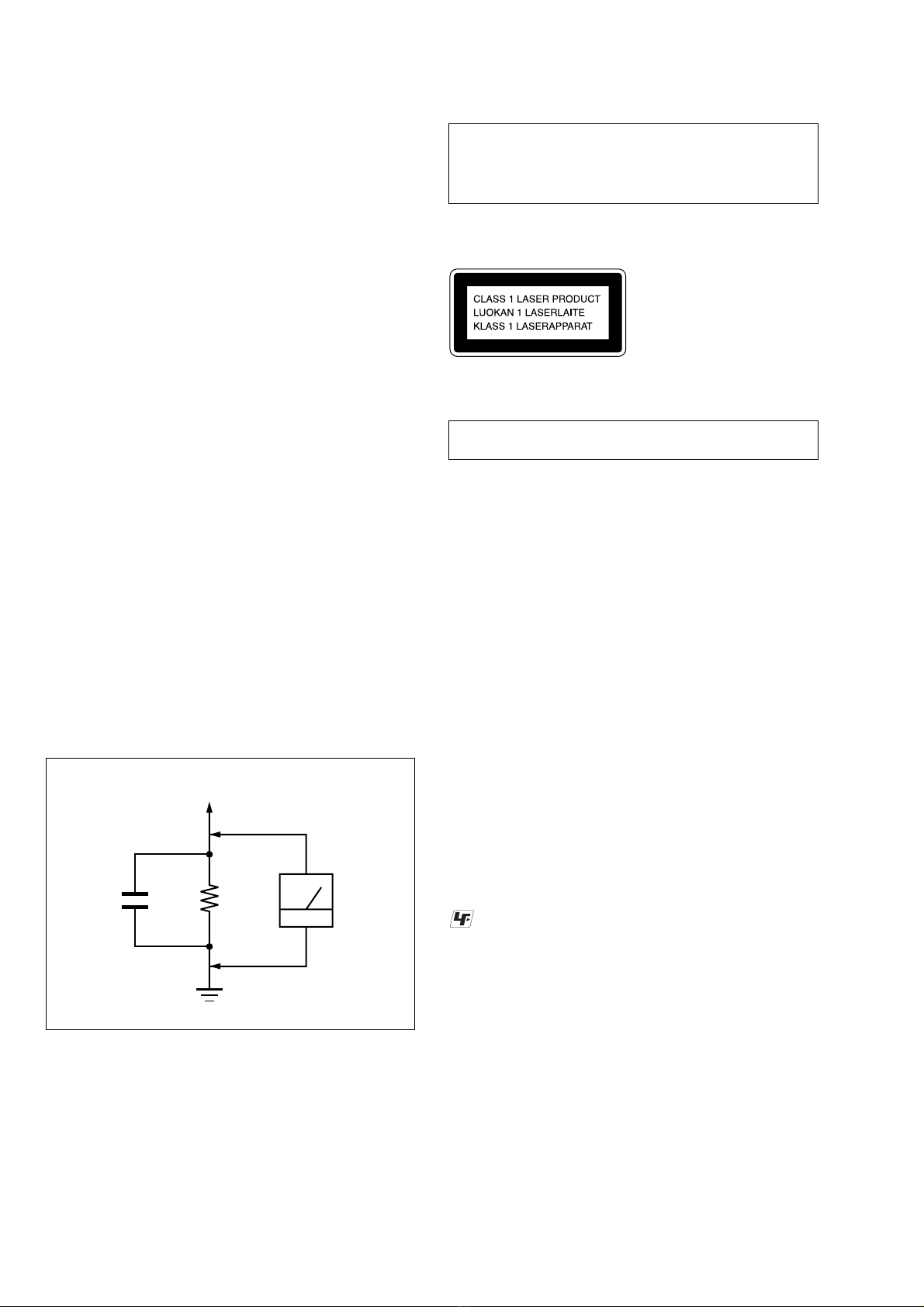
Fig. A. Using an AC voltmeter to check AC leakage.
1.5 k
Ω
0.15
µ
FAC
voltmete
r
(0.75 V)
To Exposed Metal
Parts on Set
Earth Ground
CAUTION
Use of controls or adjustments or performance of procedures
other than those specified herein may result in hazardous
radiation exposure.
Notes on chip component replacement
•Never reuse a disconnected chip component.
•Notice that the minus side of a tantalum capacitor may be dam-
aged by heat.
Flexible Circuit Board Repairing
•Keep the temperature of the soldering iron around 270 ˚C during
repairing.
•Do not touch the soldering iron on the same conductor of the
circuit board (within 3 times).
•Be careful not to apply force on the conductor when soldering or
unsoldering.
SAFETY CHECK-OUT
After correcting the original service problem,perform the following
safety check before releasing the set to the customer:
Check the antenna terminals, metal trim, “metallized” knobs, screws,
and all other exposed metal parts for AC leakage.
Check leakage as described below.
LEAKAGE TEST
The AC leakage from any exposed metal part to earth ground and
from all exposed metal parts to any exposed metal part having a
return to chassis, must not exceed 0.5 mA (500 microamperes.).
Leakage current can be measured by any one of three methods.
1. A commercial leakage tester, such as the Simpson 229 or RCA
WT-540A. Follow the manufacturers’instructions to use these
instruments.
2. A battery-operated AC milliammeter. The Data Precision 245
digital multimeter is suitable for this job.
3. Measuring the voltagedrop across a resistor bymeansof aVOM
or battery-operatedAC voltmeter. The “limit” indication is 0.75
V, so analog meters must have an accurate low-voltage scale.
The Simpson 250 and Sanwa SH-63Trd are examples of a
passiveVOM that is suitable. Nearly all battery operated digital
multimeters that have a 2VAC range are suitable. (See Fig.A)
This appliance is classified as a CLASS 1 LASER product.
This label is located on the rear exterior.
Laser component in this product is capable of emitting radiation
exceeding the limit for Class 1.
The laser diode in the optical pick-up block may suffer electrostatic
break-down because of the potential difference generated by the
charged electrostatic load, etc. on clothing and the human body.
During repair, pay attention to electrostatic break-down and also
use the procedure in the printed matter which is included in the
repair parts.
The flexible board is easily damaged and should be handled with
care.
NOTES ON LASER DIODE EMISSION CHECK
The laser beam on this model is concentrated so as to be focused on
the disc reflective surface by the objective lens in the optical pick-
up block. Therefore, when checking the laser diode emission,
observe from more than 30 cm away from the objective lens.
LASER DIODE AND FOCUS SEARCH OPERATION
CHECK
Carry out the “S curve check” in “CD section adjustment”andcheck
that the S curve waveforms is output three times.
UNLEADED SOLDER
Boards requiring use of unleaded solder are printed with the lead-
free mark (LF) indicating the solder contains no lead.
(Caution: Some printed circuit boards may not come printed with
the lead free mark due to their particular size)
: LEAD FREE MARK
Unleaded solder has the following characteristics.
•Unleaded solder melts at a temperature about 40 ˚C higher than
ordinary solder.
Ordinary soldering irons can be used but the iron tip has to be
applied to the solder joint for a slightly longer time.
Soldering irons using a temperature regulator should be set to
about 350 ˚C .
Caution: The printed pattern (copper foil) may peel away if the
heated tip is applied for too long, so be careful!
•Strong viscosity
Unleaded solder is more viscous (sticky, less prone to flow) than
ordinary solder so use caution not to let solder bridges occur such
as on IC pins, etc.
•Usable with ordinary solder
It is best to use only unleaded solder but unleaded solder may
also be added to ordinary solder.
NOTES ON HANDLING THE OPTICAL PICK-UP
BLOCK OR BASE UNIT

5
HCD-HP7
Service Position of theTape Cassette Mechanism Deck
Service Position of the CD Mechanism Deck
Connect jig (extension cable J-2501-248-A)
to the MAIN board (CN302) and CONNECTOR board (CN701).
Connect jig (extension cable J-2501-011-B)
to the MAIN board (CN301) and BD board (CN710).

6
HCD-HP7 SECTION 2
GENERAL This section is extracted
from instruction manual.
Main unit
CD SYNC 9(17)
DIMMER ql (23)
DISC 1 – 5 qs (9, 10, 11, 29)
Disc slot qf
DISPLAY 6(15, 22, 23, 29)
Display window 3
FUNCTION w; (9, 11, 16, 17, 25)
GROOVE qj (18)
PHONES jack qd
PLAY MODE 7(9, 11, 16, 17,
21)
PRESET EQ qk (18)
PRESET/ALBUM +/– wa (10,
11, 13, 14)
REC PAUSE/START 0(17)
Remote sensor 2
REPEAT 8(11)
Tape deck 4
TUNER/BAND 5(13, 14, 17)
TUNING +/– qa (13, 14)
VOLUME qh (20)
?/1 (power) 1(7, 8, 14, 20, 21,
29)
m/M (rewind/fast forward)
qa (10, 16)
./> (go back/go forward)
qa (8, 10, 11,16, 20, 21)
x(stop) 5(10, 16, 17, 21, 29)
X(pause) 5(10, 16)
CD N(play) 5(10, 12)
TAPE nN (play) 5(16, 17,
21)
DISC 1 Z– DISC 5 Z(eject) qg
(9, 10)
List of button locations and reference pages
ALPHABETICAL ORDER
A – G P – Z
BUTTON DESCRIPTIONS

7
HCD-HP7
Remote control
ALBUM +/– qf (10, 11)
CD ql (9, 11, 17)
CLEAR 5(12)
CLOCK/TIMER SELECT 2
(21, 22)
CLOCK/TIMER SET 3(8, 20,
21)
DISPLAY 6(15, 22, 23, 29)
D. SKIP 7(10, 11)
ENTER qh (8, 11, 13, 20, 21)
GAME (MD)*1q; (17, 25)
GROOVE qd (18)
ILLUMINATION*2qg
PLAY MODE w; (9, 11, 16, 17,
21)
PRESET EQ qj (18)
PRESET +/– 5(13, 14)
REPEAT/FM MODE wa (11, 14)
SLEEP 1(20)
SURROUND qa (19)
TAPE A/B*39(16, 17)
TUNER BAND qk (13, 14, 17)
TUNER MEMORY 8(13)
TUNING +/– 5(13, 14)
VOL +/– qs (20)
?/1 (power) 4(7, 8, 20, 21, 29)
m/M (rewind/fast forward)
5(10, 16)
./> (go back/go forward)
5(8, 10, 11, 16, 20, 21)
x(stop) 5(10, 16, 17, 21, 29)
X(pause) 5(10, 16)
N(play) 5(10, 12, 16)
*1 This button is used to switch
to MD function.
*2 This button cannot be used in
this system.
*3 This button is used to switch
to TAPE function.
ALPHABETICAL ORDER
A – G I – Z
BUTTON DESCRIPTIONS
12 34
5
6
7
8
9
q;
qa
qs
qd
qf
qg
qh
qj
qk
ql
w;
wa
Use buttons on the remote for the operation.
1Press ?/1 to turn on the system.
2Press CLOCK/TIMER SET.
3Press ./> repeatedly to set the
hour.
4Press ENTER.
5Press ./> repeatedly to set the
minute.
6Press ENTER.
The clock starts working.
To adjust the clock
1Press CLOCK/TIMER SET.
2Press ./> to select “CLOCK SET”,
then press ENTER.
3Do the same procedures as step 3 to 6
above.
Note
The clock settings are canceled when you disconnect
the power cord or if a power failure occurs.
Setting the clock

8
HCD-HP7 SECTION 3
DISASSEMBLY
• This set can be disassembled in the order shown below.
CD MECHANISM DECK
(CDM69CH-K6BD71C)
PWR AMP BOARD,
POWER TRANSFORMER
FRONT PANEL SECTION
BACK PANEL SECTION
PANEL BOARD
MAIN BOARD
BASE UNIT SECTION
CASE (SIDE-L) (SIDE-R),
TAPE MECHANISM DECK
(CMAL1Z234A))
RUBBER ROLLER
(SLIDER) ASSY
TIMING BELT
(FRONT/REAR) CAM (GEAR)
SENSOR BOARD
SW BOARD,
BRACKET (TOP) ASSY
BASE UNIT
(BU-K6BD71C) MOTOR (MODE)
ASSY (MODE) (M771)
MOTOR (ROLLER)
ASSY (ROLLER) (M781)
MOTOR (STOCKER) ASSY
(STOCKER) (M761) CONNECTOR BOARD
SET
BD BOARD
Ver 1.1 2003.11

9
HCD-HP7
Note: Follow the disassembly procedure in the numerical order given.
3-1. Case (Side-L)(Side-R),Tape Mechanism Deck (CMAL1Z234A)
3-2. Front Panel Section
9
connector
(6p)
2
two screws
(BVTP3
×
16
)
qa
four screws
(BVTP2.6
×
8)
qs
shield plate (case)
qd
tape mechanism deck
(CMAL1Z234A)
8
top panel section
3
case (side-R)
1
four screws
(case3 TP2)
4
four screws
(case3 TP2)
6
case (side-L)
5
two screws
(BVTP3
×
16
)
7
two screws
(BVTP3
×
16
)
q;
w
ire (flat type) 8p
3
connector
(CN305)
1
screw
(BVTP3
×
8
)
5
two screws
(BVTP3
×
8)
2
w
ire (flat type)
9p (CN303)
4
w
ire (flat type)
37p (CN402)
6
front panel section

10
HCD-HP7
3-3. Panel Board
3-4. Back Panel Section
2
ten screws
(BVTP2.6
×
8
)
1
knob
(VOL)
3
six claws
4
PANEL board
8
back panel section
3
two screws
(BVTP3
×
8)
2
four screws
(BVTP3
×
10
)
6
connector
(CN908)
5
connector
(CN905)
7
connector
(CN904)
4
connector
(CN503)
1
w
ire (flat type)
11p (CN101)

11
HCD-HP7
3-5. MAIN Board
3-6. PWR AMP Board, PowerTransformer
3
connector
(CN404)
2
two screws
(BVTP3
×
8
)
9
MAIN board
6
w
ire (flat type)
19p (CN301)
7
w
ire (flat type)
27p (CN302)
1
connector
(CN907)
5
w
ire (flat type)
9p (CN303)
4
w
ire (flat type)
37p (CN402)
8
connector
(CN305)
2
screw
(BVTP3
×
8)
1
connector
(CN902)
3
four screws
(BVTP3
×
8)
4
PWR AMP boar
d
5
four screws
(BVTT4
×
8)
6
power transformer

12
HCD-HP7
3-7. CD Mechanism Deck (CDM69CH-K6BD71C)
3-8. Base Unit Section
4
four screws
(BVTP3
×
8
)
7
CD mechanism deck
(CDM69CH-K6BD71C)
2
two screws
(BVTP3
×
8
)
1
two screws
(BVTP3
×
8
)
6
w
ire (flat type)
19p (CN710)
5
w
ire (flat type)
27p (CN701)
3
blacket (TR)
4
boss
6
boss
3
boss
5
boss
1
floating
screw
(+PTPWHM2.6)
2
screw
(DIA. 12)
7
base unit section

13
HCD-HP7
3-9. Base Unit (BU-K6BD71C)
3-10. BD Board
q;
base unit (BU-K6BD71C)
4
floating screw
(+PTPWHM2.6)
7
insulator (213)
2
floating screw
(+PTPWHM2.6)
9
insulator (213)
3
floating screw
(+PTPWHM2.6)
8
insulator (213)
1
floating screw
(+PTPWHM2.6)
6
insulator (213)
5
2
Remove the solder
(four portions).
4
BD board
3
wire (flat type)
(16core)
1
screw
(BVTP2.6
×
8)

15
HCD-HP7
3-13. CONNECTOR Board
3-14. Motor (Stocker) Assy (Stocker)(M761)
3
1
Remove five solders.
– bottom view –
CONNECTOR board
2
four screws
(BVTP2.6
×
8)
4
connector
(CN710)
6
connector
(CN703)
5
connector
(CN702)
7
CONNECTOR board
4
5
STOCKER MOTOR
board
3
two screws
(BVTP2.6
×
8)
2
Remove two solder
s
6
motor (stocker) assy
(stocker) (M761)
1
belt (mode)

16
HCD-HP7
3-15. Motor (Roller) Assy (Roller)(M781)
3-16. Motor (Mode) Assy (Mode)(M771)
1
belt (roller V)
4
ROLLER MOTOR
boar
d
2
Remove two solders.
3
two screws
5
motor (roller) assy
(roller)(M781)
1
Remove five solders
of rotary encoder.
2
Remove two solders
of motor (M771)
MODE MOTOR
board
3
two screws
(BVTP2.6
×
8)
4
MODE MOTOR board
5
belt (mode V)
6
motor (mode) assy
(mode) (M771)

17
HCD-HP7
3-17. Rubber Roller (Slider) Assy
3-18. Timing Belt (Front/Rear)
qg
sub chassis
qf
screw
(BVTP2.6
×
8)
8
step screw
qs
step screw
5
step screw
9
tension
spring
(slider 2)
6
tension spring
(base slider 4)
0
rubber roller
(slider 1) assy
7
rubber roller
(slider 1) assy
qa
rubber roller
(slider 2) assy
qd
rubber roller
(slider 4) assy
3
tension spring
(base slider 5
)
1
step screw
4
rubber roller
(slider 5) assy
2
rubber roller
(slider S) assy
Note: Refer to assembly (Section 4)
2
gear (mode cam)
: Note
1
screw
(PTPWH2.6
×
8)
3
slider (mode cam) assy
5
two gears
(center)
7
two gears (center)
8
timing belt (rear)
9
timing belt (rear)
4
gear
(timing)
6
timing belt
(front)
timing belt
(rear)
When install three timing belts,
its pass under each claws.
timing belt
(rear)
timing belt (front)
claw
claw
claw
claw

18
HCD-HP7
3-19. Cam (Gear)
3-20. SENSOR Board
qf
cam (gear)
: Note
qs
gear(mode cam)
0
gear
(mode C)
:Note
4
gear (mode 5)
8
gear (mode D)
6
gear (mode 5)
1
screw(PTPWH2.6
×
8)
7
screw (PTPWH2.6
×
8)
9
screw
(PTPWH2.6
×
8)
qa
screw
(PTPWH2.6
×
8)
3
screw (PTPWH2.6
×
8)
5
screw (PTPWH2.6
×
8
)
2
pulley
(mode deceleration)
qd
screw
Note: Refer to assembly
(Section 4).
ql
harness
qd
gear (eject lock)
q;
cam (eject lock)
: Note
qh
two claws
qj
rotary encode
r
(S771)
qf
gear
(mode B)
w;
screw
(BVTP2.6
×
8)
qg
screw
(PTPWH2.6
×
8)
wa
SENSOR board
8
shaft
(shutter)
7
compression spring
(shutter)
qs
cam (BU U/D)
qa
screw
(PTPWH2.6
×
8)
3
screw
(BVTP2.6
×
8)
1
screw
(PTPWH2.6
×
8)
4
two screws
(BVTP2.6
×
8)
2
lever shutter (A)
5
base (shutter) block
6
gear (mode A)
9
screw
(PTPWH2.6
×
8)
qk
claw
Note: Refer to assembly (Section 4).

19
HCD-HP7
• This set can be assembled in the order shown below.
4-1. How to Install the Cam (Eject Lock)
SECTION 4
ASSEMBLY
4-2. How to Install the Cam (Gear)
mark
cam (BU U/D)
cam (eject lock)
– bottom view • front –
gear (eject lock)
1
Rotate the cam (BU U/D) fully in the direction of arrow.
2
Engage the gear (eject lock) and the gear of the cam (eject lock)
aligning the mark with the center of the gear (eject lock).
boss
cam (gear)
mark
cam (BU U/D)
– bottom view • front –
1
Check that the cam (BU U/D) can not be rotated in the direction of arrow.
2
Align the mark on the cam (gear) with the boss as shown in the figure
and install the cam (gear).

20
HCD-HP7
4-3. How to Install the Gear (Mode C)
4-4. How to Install the Gear (Mode Cam)
1
Align the mark on the rotary encoder (S771) with the projection of the assy.
2
Check that the cam (BU U/D) can not be rotated in the direction of arrow.
3
Install the gear (mode C)
– bottom view • front –
gear (mode C)
rotary encoder
(S771) cam (BU U/D)
mark projection chassis
mark
B
slider (mode cam) assy
shaft
mark
A
mark
D
gear (mode cam)
cam (gear)
mark
C
1
Slide the shaft in the direction of arrow.
2
Align mark
A
on the gear (mode cam) with mark
B
on the slider (mode cam) assy,
then install the gear (mode cam).
3
Check that mark
C
on the gear (mode cam) is in alignment with mark
D
on the cam (gear).
– bottom view • front –
Table of contents
Other Sony Stereo System manuals

Sony
Sony ZS-PS55B User manual

Sony
Sony CMT-FX300i Marketing User manual

Sony
Sony WHG-SLK1i - Audio System Component Setup guide

Sony
Sony SRS-BTS50 User manual

Sony
Sony ICF-CS15iPN User manual

Sony
Sony HCD-VX3A User manual

Sony
Sony CDP-M11C User manual

Sony
Sony CHC-CL3 User manual

Sony
Sony MHC-M500AV User manual

Sony
Sony CMT-CP100K User manual

Sony
Sony CMT-SPZ50 User manual

Sony
Sony HCD-DX60AV User manual

Sony
Sony MHC-RXD3 - 3 Ch Mini System User manual

Sony
Sony HCD-H505 User manual

Sony
Sony MHC-V41D User manual

Sony
Sony CMT-DX400A User manual

Sony
Sony MHC-GR8 User manual

Sony
Sony FH-211W User manual

Sony
Sony FST-ZX6 User manual

Sony
Sony HCD-GRX30 User manual