manuals.online logo
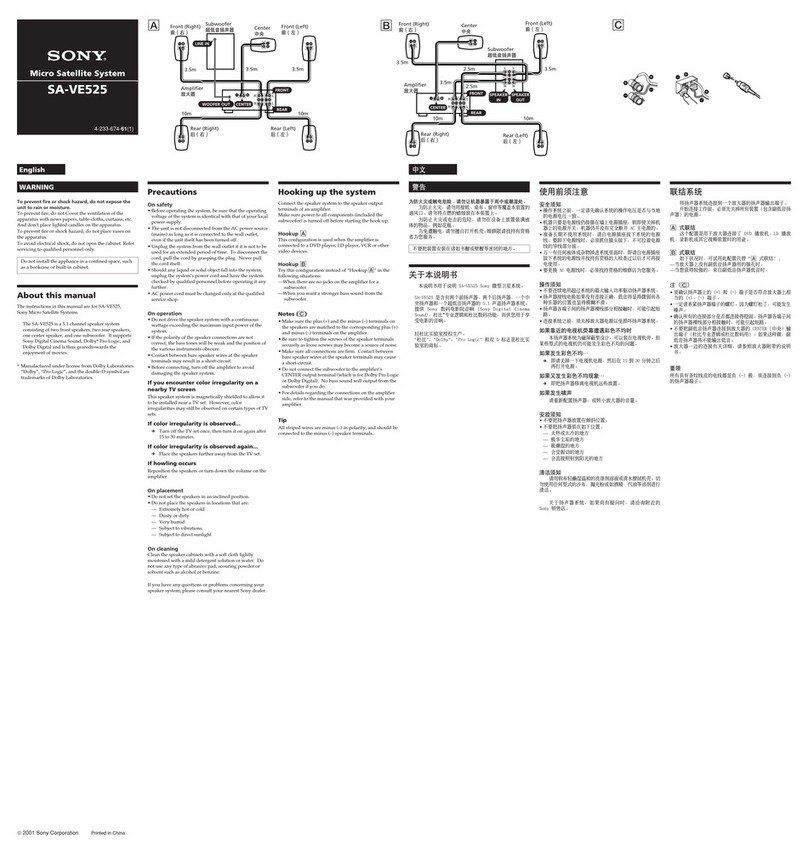
Brands
  1. Home
  2. •
  3. Brands
  4. •
  5. Sony
  6. •
  7. Stereo System
  8. •
  9. Sony FH-215R User manual

Sony FH-215R User manual

Other manuals for FH-215R

1

This manual suits for next models

1

Other Sony Stereo System manuals

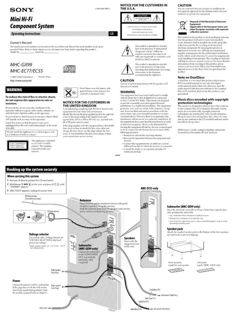
Sony MHC-GX570XM User manual

Sony

Sony MHC-GX570XM User manual

Sony HCD-GTR6 User manual

Sony

Sony HCD-GTR6 User manual

Sony HCD-GRX7 User manual

Sony

Sony HCD-GRX7 User manual

Sony HCD-RG40 User manual

Sony

Sony HCD-RG40 User manual

Sony HCD-XGV11AV User manual

Sony

Sony HCD-XGV11AV User manual

Sony MHC-V90DW User manual

Sony

Sony MHC-V90DW User manual

Sony HCD-N555AVK User manual

Sony

Sony HCD-N555AVK User manual

Sony HCD-RG190 User manual

Sony

Sony HCD-RG190 User manual

Sony HCD-GX750 - System Components User manual

Sony

Sony HCD-GX750 - System Components User manual

Sony MHC-GX99 User manual

Sony

Sony MHC-GX99 User manual

Sony CMT-SBT300W User manual

Sony

Sony CMT-SBT300W User manual

Sony MHC-V800 User manual

Sony

Sony MHC-V800 User manual

Sony MHC-991AV User manual

Sony

Sony MHC-991AV User manual

Sony SRS-X9 Installation and maintenance instructions

Sony

Sony SRS-X9 Installation and maintenance instructions

Sony SRS-BTX500 User manual

Sony

Sony SRS-BTX500 User manual

Sony SRS-XB2 User manual

Sony

Sony SRS-XB2 User manual
Sony CMT-L1 - Micro Hi Fi Component System User manual
Sony

Sony CMT-L1 - Micro Hi Fi Component System User manual
Sony XO-D301 User manual

Sony

Sony XO-D301 User manual

Sony HCD-GNX600 Building instructions

Sony

Sony HCD-GNX600 Building instructions

Sony MHC-RG595 User manual

Sony

Sony MHC-RG595 User manual

Sony AIR-SW10TI - Wireless Audio Transmitter... User manual

Sony

Sony AIR-SW10TI - Wireless Audio Transmitter... User manual

Sony MHC-RXD3/GRX20 User manual

Sony

Sony MHC-RXD3/GRX20 User manual

Sony HCD-DX90 User manual

Sony

Sony HCD-DX90 User manual

Sony HCD-VX77 User manual

Sony

Sony HCD-VX77 User manual

Popular Stereo System manuals by other brands

Philips MCM398D/12 user manual

Philips

Philips MCM398D/12 user manual

LG OM4560 owner's manual

LG

LG OM4560 owner's manual

JVC UX-G3 instructions

JVC

JVC UX-G3 instructions

Odys ODYS - LOOP instruction manual

Odys

Odys ODYS - LOOP instruction manual

Aiwa NSX-AJ700 Service manual

Aiwa

Aiwa NSX-AJ700 Service manual

Panasonic SC-AK100 operating instructions

Panasonic

Panasonic SC-AK100 operating instructions

Sharp CD-G10000V Operation manual

Sharp

Sharp CD-G10000V Operation manual

Bogen NEARSCAPES 4.1 manual

Bogen

Bogen NEARSCAPES 4.1 manual

Panasonic SCPM29 - MINI HES W/CD PLAYER operating instructions

Panasonic

Panasonic SCPM29 - MINI HES W/CD PLAYER operating instructions

Meyer LD-3 operating instructions

Meyer

Meyer LD-3 operating instructions

THOMSON MIC302U manual

THOMSON

THOMSON MIC302U manual

Philips MCM530 Service manual

Philips

Philips MCM530 Service manual

Cetacea Sound CVS-II user guide

Cetacea Sound

Cetacea Sound CVS-II user guide

Denon UCD-250 Service manual

Denon

Denon UCD-250 Service manual

Exibel BDX600-UK user manual

Exibel

Exibel BDX600-UK user manual

Sanyo DC-F320 Service manual

Sanyo

Sanyo DC-F320 Service manual

Philips FWM583X Specifications

Philips

Philips FWM583X Specifications

Onkyo CBX 300 - CD / MP3 Clock Radio instruction manual

Onkyo

Onkyo CBX 300 - CD / MP3 Clock Radio instruction manual

manuals.online logo
manuals.online logoBrands
  • About & Mission
  • Contact us
  • Privacy Policy
  • Terms and Conditions

Copyright 2025 Manuals.Online. All Rights Reserved.

SERVICE
MANUAL
=
vee
ais
FH-1215CD:
UK
Model
‘Dolby’
and
the
double-D
symbo!
are
the
trade
marks
of
Dolby
laboratories
Licensing
Corporation.
Noise
reduction
e
FH-215R
consists
of
ST-215,
TA-215,
TC-215R,
APM-215.
system
manufactured
under
license
from
Dolby
Laboratories
@FH-1215CD
consists
of
ST-215,
TA-215,
TC-215R,
CDP-
Licensing
Corporation.
17F.
CONTENTS
FH-215R/1215CD
ST-215|
(AEP,
UK
Model)
Page
Page
MODEL
IDENTIFICATIONS
............
3
NOTE
ON
LITHIUM
BATTERY
SPECIFICATION
............00
000s
4
NOTE
ON
CERAMIC
FILTER
(CF101,
102)
FEATURES:
sics
iod
Scene
8%
Bod are
eee
de
5
REPLACEMENT
AND
DIODE
D314,
315
NOTE
ON
LITHIUM
BATTERY
.........
5
CONNECTION
...........
00
ce
eee
ST-1
CONNECTOR’S
SIGNAL
ASSIGNMENT
...
6
SECTION
1
ADJUSTMENTS
...........
ST-2
FUNCTION
OF
CONTROLS
............
7
SECTION
2
DIAGRAMS
..............
ST-5
EXPLODED
VIEW
AND
PARTS
LIST
.....
10
2-1.
MOUNTING
DIAGRAM......
ST-5
2-2.
SCHEMATIC
DIAGRAM
.....
ST-7
SECTION
3
EXPLODED
VIEW
AND
See
CDP-17F
SERVICE
MANUAL
Separately
PARTS
LIST
............
ST-11
issued
for
the
information
of
CDP-17F.
~—
Continued
on
page
2
—
SAFETY-RELATED
COMPONENT
WARNING!!
COMPONENTS
IDENTIFIED
BY
SHADING
AND
MARK
A
ON
THE
SCHEMATIC
DIAGRAMS
AND
IN
THE
PARTS
LIST
ARE
CRITICAL
TO
SAFE
OPERATION.
REPLACE
THESE
COMPONENTS
WITH
SONY
PARTS
COMPACT
HI-DENSITY
WHOSE
PART
NUMBERS
APPEAR
AS
SHOWN
IN
THIS
MANUAL
OR
IN
SUPPLEMENTS
PUBLISHED
BY
SONY.
COM
P
0
N
F
NT
SYSTEM
of
Ld
guess
eel
:
MICROFILM
FH-215R/1215CD
ST-215|
(E
Model)
_Page
NOTE
ON
CERAMIC
FILTER
(CF101,
102)
REPLACEMENT
AND
DIODE
D314,
315
CONNECTION
............
00200000
ST-1
SECTION
1
ADJUSTMENTS
...........
ST-3
SECTION
2
DIAGRAMS
..............
ST-7
2-1.
MOUNTING
DIAGRAM
......
ST-7
2-2.
SCHEMATIC
DIAGRAM
.....
ST-9
SECTION
3
EXPLODED
VIEW
AND
PARTS
LIST
............
ST-13
TA-215
Page
1.
MOUNTING
DIAGRAM............
TA-5
2.
SCHEMATIC
DIAGRAM
...........
TA-9
3.
EXPLODED
VIEW
AND
PARTS:
LIST.
ces
oho
ie
tet
ok
TA-13
SECTION
1
SECTION
2
2-1.
2-2.
SECTION
3
3-1.
3-2.
SECTION
4
SECTION
5
1.
DISASSEMBLY
2.
WIRING
DIAGRAM
Page
SERVICING
PRECAUTION
..
TC-2
ADJUSTMENTS
...........
TC-3
MECHANICAL
ADJUSTMENT
.
TC-3
ELECTRICAL
ADJUSTMENT.
.
TC-4
DIAGRAMS
..............
TC-8
MOUNTING
DIAGRAM
......
TC-8
SCHEMATIC
DIAGRAM
....
TC-11
EXPLODED
VIEW
AND
PARTS
LIST
............
TC-15
ELECTRICAL
PARTS
LIST...
TC-20
3.
EXPLODED
VIEW
AND
PARTS
LIST
|
FH-215R/1215CD
MODEL
IDENTIFICATION
—
Specification
Label
—
TA-215.......
E,
Saudi
Arabia,
AEP,
UK
Model
Ye
arene
are
E2
Model
FH-215R
.....
G-AEP
Model
BLANK
......
E3,
Saudi
Arabia,
AEP,
UK
Model
SONY.
MODEL
NO.
APM-215
SPEAKER
SYSTEM
IMPEDANCE:
622
POWER
HANDLING
CAPACITY:
120/220/240
V
~
50/60Hz110W.....
E,
Saudi
Arabia
Model
jusic90WDIN.....
AEP,
UK
Model
220V
~
SO/60Hz110W
...........
AEP
Model
BLANK
.........
E2,
E3,
Saudi
Arabia
Model
240V~50Hz220W
.............
UK
Model
SONY:
MODEL
NO.
ST-215
FM
STEREO/FM-AM
TUNER
FREQUENCY
RANGE
4
E,
Saudi
Arabia
Model
FM:
87.5—108MHz
MW:
522-161
Hz
cae
LW:
144-288
kHz
Model
FM:
87.5—108MHz
SW,:
9.5—21.75MHz
}
SW.
:
3.2
—
7.3
MHz
MW:
531
—
1,602
kHz
FH-215R/1215CD
SPECIFICATIONS
ST-215
Tuner
System
FM
stereo,
FM/AM
superheterodyne
tuner
Quartz-locked
PLL
digital
synthesizer
system
FM
tuner
section
Tuning
range
87.5
-
108
MHz
Antenna
Telescopic
antenna
Antenna
terminals
75
ohms
unbalanced
intermediate
frequency
10.7
MHz
Usable
sensitivity
2.3yuV
(S/N
=
30
dB/75
ohms)
Signal-to-noise
ratio
78
dB
(mono)
70
dB
(stereo)
Harmonic
distortion
at
1
kHz
0.2%
(mono)
0.5%
(stereo)
Separation
at1
kHz
40dB
Selectivity
at
400
kHz
55
dB
MW/LW
tuner
section
(for
AEP,
UK
model)
MW
LW
Tuning
range
522
-
1,611
kHz
144
-
288
kHz
Antenna
Built-in
ferrite
bar
antenna
External
antenna
terminal
a
Intermediate
frequency
450
kHz
Built-in
ferrite
bar
250
pV/m
(999
kHz}
antenna
Usable
sensitivity
500
pV/m
(230
kHz)
150
pV
(230
kHz)
52
dB
(50
mV/m)
External
antenna
100
pV
(999
kHz)
Signal-to-noise
ratio
Harmonic
distortion
0.3%
(50
mV/m,
400
Hz)
SW/MW
tuner
section
(for
E
mode!)
9.5
-
21.75
MHz
§31
-
1,602
KHz
(at
9
kHz
step)
530
-
1,610
kHz
(at
10
kHz
step)
Tuning
range
MHz
Antenna
Telescopic
antenna
Built-in
ferrite
bar
antenna
External
antenna
terminal
Intermediate
frequency
450
kHz
Usable
sensitivity
Built-in
ferrite
bar
-
antenna
250
pVim
(999
or
1,000
kHz)
€xternal
antenna
30
uv
100
uV
(15
MHz)
(999
or
1,000
kHz)
52
dB
(50
mVim)
Signal-to-noise
ratio
50
dB
(5
mV)
Harmonic
distortion
0.3%
0.3%
(5
mV,
400
Hz)
|
(50
mV/m,
400
Hz)
General
Dimensions
Approx.
215
x
55
x
240
mm
(wih/d)
(B42
x
24a
x
94/2
Inches)
incl.
projecting
parts
and
controls
Weight
Approx.
0.9
kg
(2
Ib)
net
TC-215R
Cassette
deck
Recording
system
4-track
2-channel
stereo
Frequency
response
DOLBY
NR
OFF
(DIN)
With
TYPE
IV
cassettes
(Sony
METAL-S)
50
-
15,000
Hz
(+3
dB)
With
TYPE
It
cassettes
(Sony
UCX)
50
-
14,000
Hz
(+3
dB)
With
TYPE
|
cassettes
(Sony
HF-S)
50
-
13,000
Hz
(+3
dB)
0.07%
WRMS
(NAB)
+0.2%
(DIN)
Approx.
215
x
120
x
250
mm
(wihid)
(B42
x
43/4
x
97/e
inches)
incl.
projecting
parts
and
controls
Weight
Approx.
2.1
kg
(4
Ib
11
02)
net
TA-215
Amplifier
Continuous
RMS
power
output
(AEP,
UK
model)
45
+
45
watts
(6
ohms,
at
1
kHz,
5%
THD)
35
+
35
watts
(6
ohms,
40
Hz
-
20kHz,
1%
THD)
Music
power
output
160
W
{6
ohms)
(AEP
model)
Peak
music
power
output
380
W
(6
ohms)
(E
model)
Wow
and
flutter
Dimensions
Inputs
Sensitivity
Impedance
PHONO
(phono
jacks)
50
kilohms
CD/AUX
(phono
jacks)
50
kilohms
MIC
(stereo
minijack)
Outputs
HEADPHONES
(stereo
Accepts
headphones
of
8
ohms
or
minijack)
more
SPEAKER
Accepts
speakers
of
6
to
16
ohms
Frequency
response
PHONO:
RIAA
curve
+
0.5
dB
CD/AUX:
40
Hz
-
30
kHz
*
3
dB
MIC:
100
Hz
-
10
kHz
*$
dB
Approx.
215
x
120
x
280
mm
(wi/h/d)
(B42
x
43/6
x
11/2
inches)
incl.
projecting
parts
and
controls
Weight
Approx.
4
kg
(8
ib
14
oz)
net
10-pin
DC
output
connector
of
TA-215
to
ST-215
Oimensions
+3V
-12V
+12V
2uA
150
MA
150
mA
Oomsceocooogo
10-pin
DC
output
connector
of
TA-215
to
TC-215R
OOOOCEBDOD
PLAY
ty
~~
PLAY
REC
REC
+16V
R
t
L
R
|
APM-215
Speaker
{for
AEP,
E
model)
Speaker
system
3
way
speaker
system
Speaker
units
Woofer:
134
cm?
APM
type
Tweeter:
5
cm
dia,
cone
type
Super
tweeter:
3.5
cm
dia,
ceramic
type
Enclosure
type
Bass
reflex
Frequency
range
60
Hz
-
20
kHz
Sensitivity
90
dBAWim
impedance
6
ohms
Dimensions
Approx.
175
x
290
x
220
mm
(wih/d)}
(7
x
1142
x
8/4
inches)
Weight
Approx.
3.3
kg
{7
Ib
5
0z)
net
per
speaker
General
Power
requirements
AEP
model:
220
V
AC,
50/60
Hz
UK
model:
240
V
AC,
50
Hz
E
model:
120,
220
or
240
V
AC
adjustable,
50/60
Hz
Power
consumption
AEP,
E
model:
110
watts
UK
model:
220
watts
Dimensions
Approx.
585
x
355
x
280
mm
(w/h/d)
(231/s
x
14
x
111/,
inches)
Incl.
projecting
parts
and
controls
Weight
AEP,
E
model
Approx.
14.3
kg
(31
Ib
9
oz)
net
Approx.
15.8
kg
(34
Ib
14.02)
in
shipping
carton
UK
model
Approx.
10
kg
(22
Ib
1
oz)
net
Approx.
120
kg
(26
Ib
8
02)
in
shipping
carton
FEATURES
Tuner
section
©
Preset
function
stores
a
total
of
20
(for
AEP,
UK
model),
or
15
(for
E
model)
stations
in
memory.
©
Preset-station-scanning
helps
you
search
for
a
desired
program.
Amplifier
section
®
Electronic
7-band
graphic
equalizer
allows
you
to
memorize
a
total
of
3
equalizer
settings.
©
Power
output
of
45W
+
45W
(for
AEP,
UK
model).
©
Peak
music
power
output
of
380W
(for
E
model).
Cassette
deck
@
Automatic
Music
Sensor
function
locates
the
beginning
of
the
selection
being
played
back
or
the
next
selection.
®
Auto
play
function
starts
playback
automatically
after
fast
winding.
Remote
control
@
A
CD
player
equipped
with
the
CONTROLS
IN
connector
such
as
the
CDP-17F
can
be
controlled
as
well
as
this
system.
FH-215R/1215CD
NOTE
ON
LITHIUM
BATTERY
WARNING
!!
ADVARSEL!
Lithiumbatteri—Eksplosionsfare
Udskiftning
ma
kun
foretages
af
en
sagkyndig,
og
som
beskrevet
i
servicemanualen.
LITHIUM
BATTERY
SHOULD
ONLY
BE
CHANGED
BY
TECHNICAL
PERSONNEL.
THERE
IS
A
RISK
FOR
EXPLOSION
AT
A
WRONG
HANDLING.
“Batteriet
ma
kun
udskiftes
med
et
batteri
af
samme
fabrikat
og
type”’.
Because
of
the
risk
for
explosion
the
battery
must
be
replaced
with
the
same
type
and
manufacture.
FH-215R/1215CD
CONNECTOR’S
SIGNAL
ASSIGNMENT
(13
F31q)
OND
(AG
+00)
dn
yoeg
(AGT-90)
NI-@
(AZT
+90)
NI+8
(HO-a)
ENO
YANNL
(HO-T)
ENO
YaNNL
€
(BT
euy)
GN
|
2
|
I
SOLIS
Ea
ees
ic!
anal
i
rs]
ae ci
a
yl
Oo
[3]
iy
<s]
=
il
co
wy
“”
<
Oo
(AT-90)
LN0-8
|
¢
(A@T+90)
LN0+8
(HO-a)
NI
MaNAL
(207
ey)
OND
(HO-T)NI
aaNNd
By
T
(H3-8)
LN
ad
(807
euy)
OND
;
(oy
euy)
ana
+|
“T1
|
to-w.sn0
a8
:
(ACT+9@)
LNO+E
L
en)
(A8T+O@)
1NO+d
|
OT
(HO-1T)
LNO
ad
(HO-T)NI
99a
(HO-M)
NI
Odd
SOIT
ie)
(A8T
+00)
NI+E
AMPLIFIER
TA-215
FUNCTION
OF
CONTROLS
TUNER
REMOTE
SENSOR
Receives
the
infrared
ray
command
transmitted
from
the
supplied
remote
commander.
2|
Display
window
O
BAND
indicator
©
FREQUENCY
indicator
@
TUNED
indicator
Appears
when
a
signal
is
tuned
in.
©
MUTING
indicator
Appears
when
the
STEREO/MUTING
switch
is
pressed.
©
MEMORY
indicator
Appears
when
the
MEMORY
button
is
pressed.
@
PRESET
(preset
station)
indicator
STEREO
indicator
Lights
up
when
an
FM
stereo
program
of
sufficient
signal
strength
is
tuned
in.
es]
=
PRESET
(10-key
station
preset)
selectors
Used
for
quick
tuning
of
frequently
used
radio
stations.
Telescopic
antenna
STEREO/MUTING
switch
Normally
keep
this
switch
engaged
to
eliminate
FM
interstation
noise
when
manually
tuning.
When
receiving
anoisy
FM
stereo
program
or
a
very
weak
station,
disengage
the
switch
for
better
reception.
(The
sound
will
be
monaural
instead.)
FH-215R/1215CD
(7}
BAND
selector
Each
time
the
button
is
pressed,
the
band
changes
in
the
following
sequence.
AEP,
UK
model:
FM>MW->LW
ey)
E
model:
FM>SW2>SW1-MW
[8]
TUNING
+
and
—
buttons
Use
to
change
radio
stations.
+:
Press
to
move
to
a
higher
frequency
station.
—:
Press
to
move
to
a
lower
frequency
station.
Hold
the
button
down
for
continuous
frequency
change.
[3]
MEMORY
SCAN
button
Press
to
scan
the
preset
stations.
MEMORY
button
[1]
ENTER
button
Completes
preset
station
selections.
[1]
PHONES
(headphones)
jack
(stereo
minijack)
[2]
Graphic
equalizer
band
selectors
Press
to
select
the
frequency
band
to
equalize.
[3]
Display
window
FH-215R/1215CD
O
SPECTRUM
ANALYZER/GRAPHIC
EQUALIZER
display
Usually
displays
the
SPECTRUM
ANALYZER.
When
the
DISPLAY
button
or
any
other
button
or
switch
controlling
the
equalizer
is
pressed,
it
changes
to
the
GRAPHIC
EQUALIZER
display.
SPECTRUM
The
sound
level
in
7
bands
is
ANALYZER
displayed.
GRAPHIC
The
equalizer
adjustment
setting
EQUALIZER
is
displayed.
©
MEMORY
indicator
Appears
when
the
EQ
MEMORY
button
is
pressed.
©
Equalizer
preset
number
indicator
Shows
the
selected
preset
number
of
the
graphic
equalizer
setting.
=
VOL
LEVEL
(volume
level)
indicator
EQ
PRESET
(equalizer
preset)
selector
Press
to
select
the
preset
number
of
the
graphic
equalizer
setting.
DISPLAY
button
Selects
the
display
function;
spectrum
analyzer
or
graphic
equalizer
display.
~
EQ
MEMORY
(equalization
memory)
button
Press
to
memorize
a
graphic
equalizer
setting.
'§]
EQ
FLAT
(flat
equalization)
switch
Press
to
listen
without
equalization.
EQ
LEVEL
(equalization
level)
contro!
buttons
Press
+
to
increase,
or
—
to
decrease
the
sound
level
in
the
selected
band
during
both
listening
and
recording.
S|
POWER
switch
DBFB
(Dynamic
Bass Feed
Back)
button
and
indicator
(for
AEP/UK
model)
SAT
(Super
Acoustic
Turbo)
button
and
indicator
(for
E
model)
Depress
to
reinforce
bass
sound
in
playback.
To
disengage
the
button,
press
it
again.
—
2|
FUNCTION
select
buttons
and
indicators
TAPE:
Press
to
listen
to
tapes.
CD:
Press
to
listen
to
or
to
record
from
compact
discs
or
auxiliary
sources.
TUNER:
Press
to
listen
to
or
to
record
radio
programs.
PHONO:
Press
to
listen
to
or
to
record
from
phonograph
records.
=
pr)
MUTING
switch
and
indicator
Press
to
momentarily
mute
the
sound
by
20
dB.
To
disengage
the
button,
press
it
again.
a
BALANCE
control
Changes
relative
strength
of
right
and
left
speaker
output.
Use
to
correct
stereo
imaging,
especially
when
the
speaker
position
is
not
symmetrical.
[15]
VOLUME
control
buttons
MIC
LEVEL
(microphone
level)
control
Slide
toward
MAX
to
increase
the
microphone
input
!evel,
and
towards
MIN
to
decrease
it.
[17]
MIC
(microphone)
jack
(stereo
minijack)
CASSETTE
DECK
|
ose
IES
eee
ee
a
=
ee
ES
TAPE
COUNTER
and
RESET
button
Use
the
counter
to
index
and
quickly
locate
desired
points
on
a
tape.
The
RESET
button
returns
the
counter
to
000.
[2]
&
EJECT
button
[3]
Tape
operation
buttons
<4
(leftward
fastwinding)
<4
(reverse
play)
®
(forward
play)
bP
(rightward
fastwinding)
@
(record)
@
(stop)
If
(pause)
O
(record
muting)
({4]
DIRECTION
MODE
selector
[5]
DOLBY
NR
*
(Noise
Reduction)
switch
*
Doiby
noise
reduction
manufactured
under
license
from
Dolby
Laboratories
Licensing
Corporation.
“DOLBY”
and
the
double-D
symbol!
DO
are
trademarks
of
Dolby
Laboratories
Licensing
Corporation.
[6]
MODE
indicators
<@
REV
(reverse):
Lights
up
when
the
reverse
side
of
the
cassette
is
being
played
back
or
recorded.
mm
PLAY:
Lights
up
during
playback
or
recording.
pm
FWD
(forward):
Lights
up
when
the
front
side
of
the
cassette
is
being
played
back
or
recorded.
as
AMS:
Lights
up
during
AMS
operation.
@
REC:
Lights
up
during
recording.
i
PAUSE:
Lights
up
while
the
tape
is in
pause.
REMOTE
COMMANDER
|
(RM-215R)
FH-215R/1215CD
The
functions
of
the
buttons
1,
2,
3
and
7
are
the
same
as
those
of
the
FH-215R
system.
Battery
installation
[1]
MUTING
switch
[2]
FUNCTION
buttons
[3]
TAPE
operation
buttons
(4]
CDTUNER
switch
Selects
the
function
of
the
numeric
buttons.
[5]
CD
player
operation
buttons
>
(play)
k@<
(previous
selection)
bP
(forward
selection)
@
(stop)
[6]
Numeric
buttons
For
the
CD
player
equipped
with
20-key
music
selector
:
Press
to
select
the
desired
selection.
For
the
tuner
:
Press
to
select
the
preset
station
number.
(7]
VOLUME
control
buttons
Before
remote
control
operation,
turn
on
the
POWER
switch
of
the
amplifier.
Battery
life
About
half
a
year
of
normal
operation
can
be
expected
when
using
the
Sony
SUM-3(NS)
batteries.
When
the
batteries
become
exhausted,
the
commander
does
not
operate.
In
this
case,
replace
both
batteries
with
new
ones.
When
the
commander
is
not
to
be
used
for
a
long
period
of
time,
remove
the
batteries
to
avoid
damage
caused
by
battery
leakage
and
corrosion.
To
control
the
FH-215R
system
Point
the
head
of
the
commander
towards
the
REMOTE
SENSOR
of
this
system.
To
control
a
CD
player
Connect
the
CONTROL
S
OUT
jack
of
the
FH-215R
system
to
the
CONTROL
S
IN
jack
of
the
CD
player,
using
the
4-pin
CD
player
connecting
cord
supplied
with
this
system.
FH-215R/1215CD
EXPLODED
VIEW
AND
PARTS
LIST
0.
Part
No.
4~920-120-01
X-4910-086-1
7-685-247-19
2-249-402-21
X-4919-631-1
OPWNrr
4-884-803-12
4-902-942-03
4-884-805-21
4-910-361-11
4-884-801-11
an
OoOuvOoann
APM-215
Description
Remarks
PLATE
(A),
SIDE
SCREW
ASSY,
SIDE
PLATE
SCREW
+KTP
3X10
TYPE2
SLIT
HANDLE
PLATE,
SEESAW
ASS’Y
6
PUSH
BUTTON
SPRING,
LEAF
SHAFT
HOLDER,
HANDLE
NUT,
PLATE
ACCESSORY
&
PACKING
MATERIAL
Part
No.
1-463-847-11
1-558-233-11
1-558-787-11
1-559-162-11
2-249-402-21
3-701-613-00
3-701-630-00
3-764-747-01
3-764-748-01
3-765-908-11
3-765-908-41
3-765-977-11
4-920-122-01
4-920-123-01
4-920-124-01
4-920-127-01
4-920-128-01
9-911-842-XX
Description
REMOTE
COMMANDER
(RM-215R)
CORD
(WITH
CONNECTOR)
(SIRCS)
4P
(UK)...CORD,
CONNECTION
CORD
(WITH
CONNECTOR)
HANDLE
BAG,
POLYETHYLENE
BAG,
POLYETHYLENE
(E2,E3).....
++++eINSTRUCTION
(CATALOGUE
}
(Saudi
Arabia)...
INSTRUCTION
(CATALOGUE
}
MANUAL,
INSTRUCTION
(AEP)...MANUAL
,
INSTRUCTION
(UK)....MANUAL,
INSTRUCTION
CUE)
620802
INDIVIDUAL
CARTON
(AEP).......
INDIVIDUAL
CARTON
(E2,E3,Saudi
Arabia)...INDIVIDUAL
CARTON
CUSHION,
UPPER
CUSHION,
LOWER
CUSHION
(F)
—
Oo—
ST-215
PACKING
MATERIAL
4-884-884-00
SHEET,
PROTECTION
TA-215
PACKING
MATERIAL
4-910-323-01
SHEET,
PROTECTION
TC-215R
PACKING
MATERIAL
3-881-664-00
SHEET,
PROTECTION
APM-215
PACKING
MATERIAL
4-920-121-01
CUSHION
4-920-151-01
SHEET,
PROTECTION