– 2 –
TABLE OF CONTENTS
1. SERVICING NOTES.............................................. 3
2. GENERAL .................................................................. 6
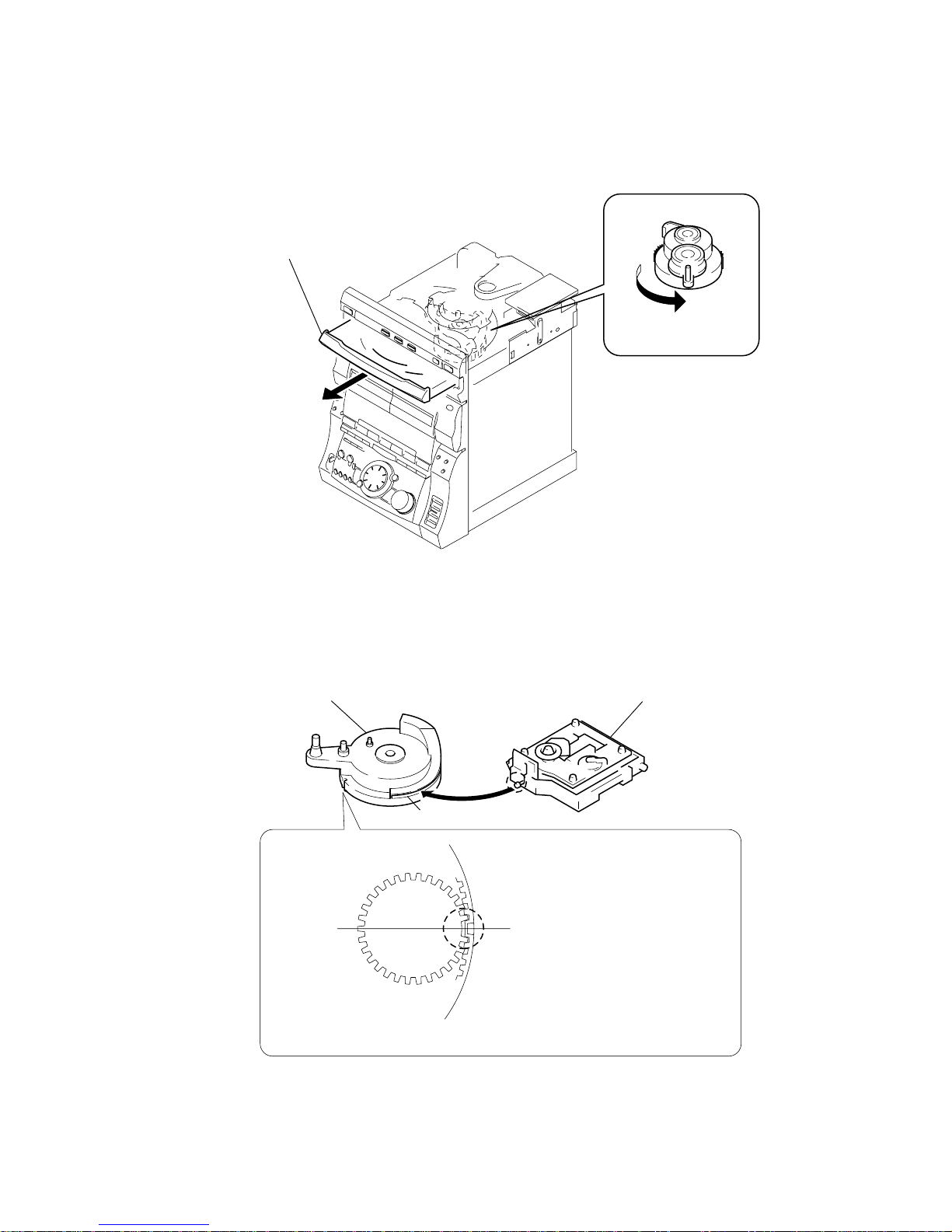
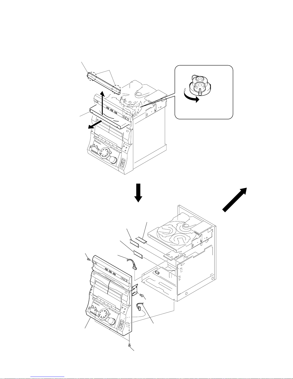
3. DISASSEMBLY ........................................................ 10
4. TEST MODE............................................................. 13
5. MECHANICAL ADJUSTMENTS...................... 16
6. ELECTRICAL ADJUSTMENTS
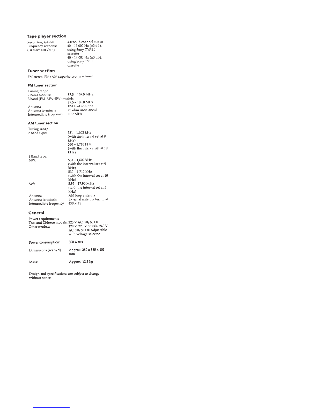
DECK Section................................................................ 16
CD Section ..................................................................... 19
VIDEO Section .............................................................. 21
7. DIAGRAMS
7-1. Block Diagram – SERVO Section –............................. 23
7-2. Block Diagram – AUDIO/VIDEO CD Section – ........ 25
7-3. Block Diagram – TAPE DECK Section – .................... 27
7-4. Block Diagram – MAIN Section (1/2) –...................... 29
7-5. Block Diagram – MAIN Section (2/2) –...................... 31
7-6. Block Diagram – DISPLAY/KEY CONTROL/
POWER SUPPLY Section – .......................................... 33
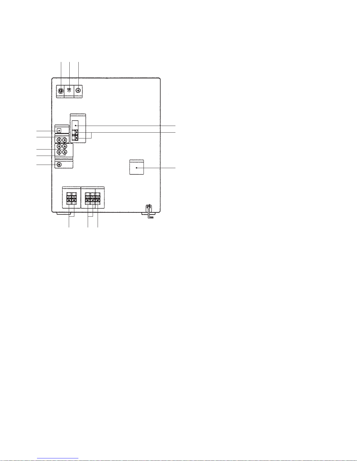
7-7. Note for Printed Wiring Boards and
Schematic Diagrams ...................................................... 36
7-8. Printed Wiring Board – BD Section – .......................... 37
7-9. Schematic Diagram – BD Section –............................ 39
7-10. Printed Wiring Board – VIDEO Section – ................... 41
7-11. Schematic Diagram – VIDEO Section (1/2) – ............ 43
7-12. Schematic Diagram – VIDEO Section (2/2) –............ 45
7-13. Printed Wiring Boards – CD MOTOR Section –......... 47
7-14. Schematic Diagram – CD MOTOR Section – ............ 49
7-15. Printed Wiring Board – TAPE DECK Section –.......... 51
7-16. Schematic Diagram – TAPE DECK Section –............ 53
7-17. Printed Wiring Board – LEAF SW Section – .............. 55
7-18. Schematic Diagram – LEAF SW Section – ................ 55
7-19. Printed Wiring Board – MAIN Section –..................... 57
7-20. Schematic Diagram – MAIN Section (1/4) –.............. 59
7-21. Schematic Diagram – MAIN Section (2/4) –............... 61
7-22. Schematic Diagram – MAIN Section (3/4) –............... 63
7-23. Schematic Diagram – MAIN Section (4/4) –............... 65
7-24. Printed Wiring Board – PANEL Section – ................... 67
7-25. Schematic Diagram – PANEL Section – ...................... 69
7-26. Printed Wiring Boards – DISPLAY Section – ............. 71
7-27. Schematic Diagram – DISPLAY Section –................. 73
7-28. Schematic Diagram
– MIC/HEADPHONE Section – ................................... 75
7-29. Printed Wiring Boards
– MIC/HEADPHONE Section – ................................... 76
7-30. Printed Wiring Board – POWER AMP Section – ........ 77
7-31. Schematic Diagram – POWER AMP Section – ........... 79
7-32. Schematic Diagram
– TRANSFORMER Section –....................................... 81
7-33. Printed Wiring Board
– TRANSFORMER Section –....................................... 83
7-34. Printed Wiring Board – SURROUND Section – ......... 84
7-35. Schematic Diagram – SURROUND Section – ............ 85
7-36. IC Pin Function Description .......................................... 94
8. EXPLODED VIEWS............................................... 106
9. ELECTRICAL PARTS LIST .............................. 114