MEX-BT4000E/BT4000P/BT4000U/BT4050U/BT4054U
9
SECTION 2
GENERAL This section is extracted
from instruction manual.
(MEX-BT4000P)
REAR
AUDIO OUT
FRONT
AUDIO OUT
SUB OUT (MONO)
SIRIUSXM
IN
REMOTE
IN*2
MIC IN*4
Notes on the control and power supply leads
REM OUT lead (blue/white striped) supplies +12 V DC when you turn
on the unit.
When your car has built-in FM/AM antenna (aerial) in the rear/side
glass, connect REM OUT lead (blue/white striped) or the accessory
power supply lead (red) to the power terminal of the existing antenna
(aerial) booster. For details, consult your dealer.
A power antenna (aerial) without a relay box cannot be used with this
unit.
Memory hold connection
When the yellow power supply lead is connected, power will always be
supplied to the memory circuit even when the ignition switch is turned
o.
Notes on speaker connection
Before connecting the speakers, turn the unit o.
Use speakers with an impedance of 4 to 8 ohms, and with adequate
power handling capacities to avoid its damage.
Do not connect the speaker terminals to the car chassis, or connect the
terminals of the right speakers with those of the left speaker.
Do not connect the ground (earth) lead of this unit to the negative (–)
terminal of the speaker.
Do not attempt to connect the speakers in parallel.
Connect only passive speakers. Connecting active speakers (with
built-in ampliers) to the speaker terminals may damage the unit.
To avoid a malfunction, do not use the built-in speaker leads installed
in your car if the unit shares a common negative (–) lead for the right
and left speakers.
Do not connect the unit’s speaker leads to each other.
Note on connection
If speaker and amplier are not connected correctly, “FAILURE” appears
in the display. In this case, make sure the speaker and amplier are
connected correctly.
Cautions
Be sure to install this unit in the dashboard of the car
as the rear side of the unit becomes hot during use.
is unit is designed for negative ground (earth) 12 V
DC operation only.
Do not get the leads under a screw, or caught in moving
parts (e.g. seat railing).
Before making connections, turn the car ignition off to
avoid short circuits.
Connect the yellow and red power supply leads only
after all other leads have been connected.
Run all ground (earth) leads to a common ground
(earth) point.
Be sure to insulate any loose unconnected leads with
electrical tape for safety.
e use of optical instruments with this product will
increase eye hazard.
Notes on the power supply lead (yellow)
When connecting this unit in combination with other
stereo components, the connected car circuit’s rating
must be higher than the sum of each component’s fuse.
When no car circuits are rated high enough, connect
the unit directly to the battery.
Précautions
Installez cet appareil sur le tableau de bord de la voiture,
car l’arrière de l’appareil chaue en cours d’utilisation.
Cet appareil est exclusivement conçu pour fonctionner
sur une tension de 12 V CC avec masse négative.
Évitez de xer des vis sur les câbles ou de coincer ceux-ci
dans des pièces mobiles (par exemple, armature de siège).
Avant d’eectuer les raccordements, coupez le moteur
pour éviter un court-circuit.
Raccordez les câbles d’alimentation jaune et rouge
seulement après avoir terminé tous les autres
raccordements.
Rassemblez tous les câbles de mise à la masse en
un point de masse commun.
Pour des raisons de sécurité, veillez à isoler avec du
ruban isolant tout câble libre non raccordé.
L’utilisation d’instruments optiques avec ce produit
augmente les risques pour les yeux.
Remarques sur le câble d’alimentation (jaune)
Lorsque cet appareil est raccordé à d’autres éléments
stéréo, la valeur nominale du circuit de la voiture
raccordé doit être supérieure à la somme des fusibles de
chaque élément.
Si aucun circuit de la voiture n’est assez puissant,
raccordez directement l’appareil à la batterie.
Connection example
Notes (-A)
Be sure to connect the ground (earth) lead before connecting the
amplier.
The alarm will only sound if the built-in amplier is used.
Connection diagram
To a metal surface of the car
First connect the black ground (earth) lead, then connect the yellow
and red power supply leads.
To a car’s illumination signal
Be sure to connect the black ground (earth) lead to a metal surface
of the car rst.
To the power antenna (aerial) control lead or
power supply lead of antenna (aerial) booster
Notes
It is not necessary to connect this lead if there is no power
antenna (aerial) or antenna (aerial) booster, or with a
manually-operated telescopic antenna (aerial).
When your car has a built-in FM/AM antenna (aerial) in the rear/
side glass, see “Notes on the control and power supply leads.”
To AMP REMOTE IN of an optional power
amplier
This connection is only for ampliers. Connecting any other system
may damage the unit.
To the interface cable of a car telephone
To the +12V power terminal which is energized
in the accessory position of the ignition switch
Notes
If there is no accessory position, connect to the +12 V power
(battery) terminal which is energized at all times.
Be sure to connect the black ground (earth) lead to a metal
surface of the car rst.
When your car has a built-in FM/AM antenna (aerial) in the rear/
side glass, see “Notes on the control and power supply leads.”
To the +12V power terminal which is energized
at all times
Be sure to connect the black ground (earth) lead to a metal surface
of the car rst.
A
SIRIUSXM IN
Satellite radio tuner
(SiriusXM)*
Syntoniseur radio satellite
(SiriusXM)*
* not supplied
non fourni
B
Exemple de raccordement
Remarques (-A)
Raccordez d’abord le câble de mise à la masse avant de raccorder
l’amplicateur.
L’alarme est émise uniquement lorsque l’amplicateur intégré est
utilisé.
Schéma de raccordement
À un point métallique de la voiture
Branchez d’abord le câble de mise à la masse noir et, ensuite, les
câbles d’alimentation jaune et rouge.
Vers le connecteur du signal d’éclairage de la
voiture
Raccordez d’abord le câble de mise à la masse noir à un point
métallique du véhicule.
Au câble de commande d’antenne électrique ou
au câble d’alimentation de l’amplicateur
d’antenne
Remarques
Il n’est pas nécessaire de raccorder ce câble s’il n’y a pas d’antenne
électrique ni d’amplicateur d’antenne, ou avec une antenne
télescopique manuelle.
Si votre voiture est équipée d’une antenne FM/AM intégrée dans
la vitre arrière/latérale, voir « Remarques sur les câbles de
commande et d’alimentation ».
Au niveau de AMP REMOTE IN de l’amplicateur
de puissance en option
Ce raccordement s’applique uniquement aux amplicateurs. Le
branchement de tout autre système risque d’endommager
l’appareil.
Vers le câble de liaison d’un téléphone de
voiture
À la borne d’alimentation +12 V qui est
alimentée quand la clé de contact est sur la
position accessoires
Remarques
S’il n’ya pas de position accessoires, raccordez la borne
d’alimentation (batterie) +12 V qui est alimentée en permanence.
Raccordez d’abord le câble de mise à la masse noir à un point
métallique du véhicule.
Si votre voiture est équipée d’une antenne FM/AM intégrée dans
la vitre arrière/latérale, voir « Remarques sur les câbles de
commande et d’alimentation ».
À la borne d’alimentation +12 V qui est
alimentée en permanence
Raccordez d’abord le câble de mise à la masse noir à un point
métallique du véhicule.
Remarques sur les câbles de commande et d’alimentation
Le câble REM OUT (rayé bleu/blanc) fournit une alimentation de +12 V
CC lorsque vous mettez l’appareil en marche.
Lorsque votre voiture est équipée d’une antenne FM/AM intégrée dans
la vitre arrière/latérale, raccordez le câble REM OUT (rayé bleu/blanc)
ou le câble d’alimentation des accessoires (rouge) à la borne
d’alimentation de l’amplicateur d’antenne existant. Pour plus de
détails, consultez votre détaillant.
Une antenne électrique sans boîtier de relais ne peut pas être utilisée
avec cet appareil.
Raccordement pour la conservation de la mémoire
Lorsque le câble d’alimentation jaune est raccordé, le circuit de la
mémoire est alimenté en permanence même si la clé de contact est sur la
position d’arrêt.
Remarques sur le raccordement des haut-parleurs
Avant de raccorder les haut-parleurs, éteignez l'appareil.
Utilisez des haut-parleurs ayant une impédance de 4 à 8 ohms avec
une capacité électrique adéquate pour éviter de les endommager.
Ne raccordez pas les bornes du système de haut-parleurs au châssis de
la voiture et ne raccordez pas les bornes du haut-parleur droit à celles
du haut-parleur gauche.
Ne raccordez pas le câble de mise à la masse de cet appareil à la borne
négative (–) du haut-parleur.
N’essayez pas de raccorderles haut-parleurs en parallèle.
Raccordez uniquement des haut-parleurs passifs. Le raccordement de
haut-parleurs actifs (avec amplicateurs intégrés) aux bornes des
haut-parleurs peut endommager l’appareil.
Pour éviter tout problème de fonctionnement, n’utilisez pas les câbles
des haut-parleurs intégrés installés dans votre voiture si l’appareil
possède un câble négatif commun (–) pour les haut-parleurs droit et
gauche.
Ne raccordez pas entre eux les câbles des haut-parleurs de l’appareil.
Remarque sur le raccordement
Si le haut-parleur et l’amplicateur ne sont pas raccordés correctement,
le message « FAILURE » s’ache. Dans ce cas, assurez-vous que les
haut-parleurs et l’amplicateur sont bien raccordés.
*1
*1
REM OUT
Max. supply current 0.4 A
Courant max. fourni 0,4 A
Fuse (10 A)
Fusible (10 A)
Blue/white striped
Rayé bleu/blanc
*5
Red
Rouge ACC
Yellow
Jaune BATTERY
Black
Noir
Light blue
Bleu ciel
Orange/white striped
Rayé orange/blanc
ATT
ILLUMINATION
White
Blanc
Green
Vert
Purple
Violet
White/black striped
Rayé blanc/noir
Gray/black striped
Rayé gris/noir
Green/black striped
Rayé vert/noir
Gray
Gris
Left
Gauche
Right
Droit
Left
Gauche
Right
Droit Purple/black striped
Rayé violet/noir
from car antenna (aerial)
à partir de l’antenne du
véhicule
*1RCA pin cord (not supplied)
*2Separate adaptor may be required.
*3not supplied
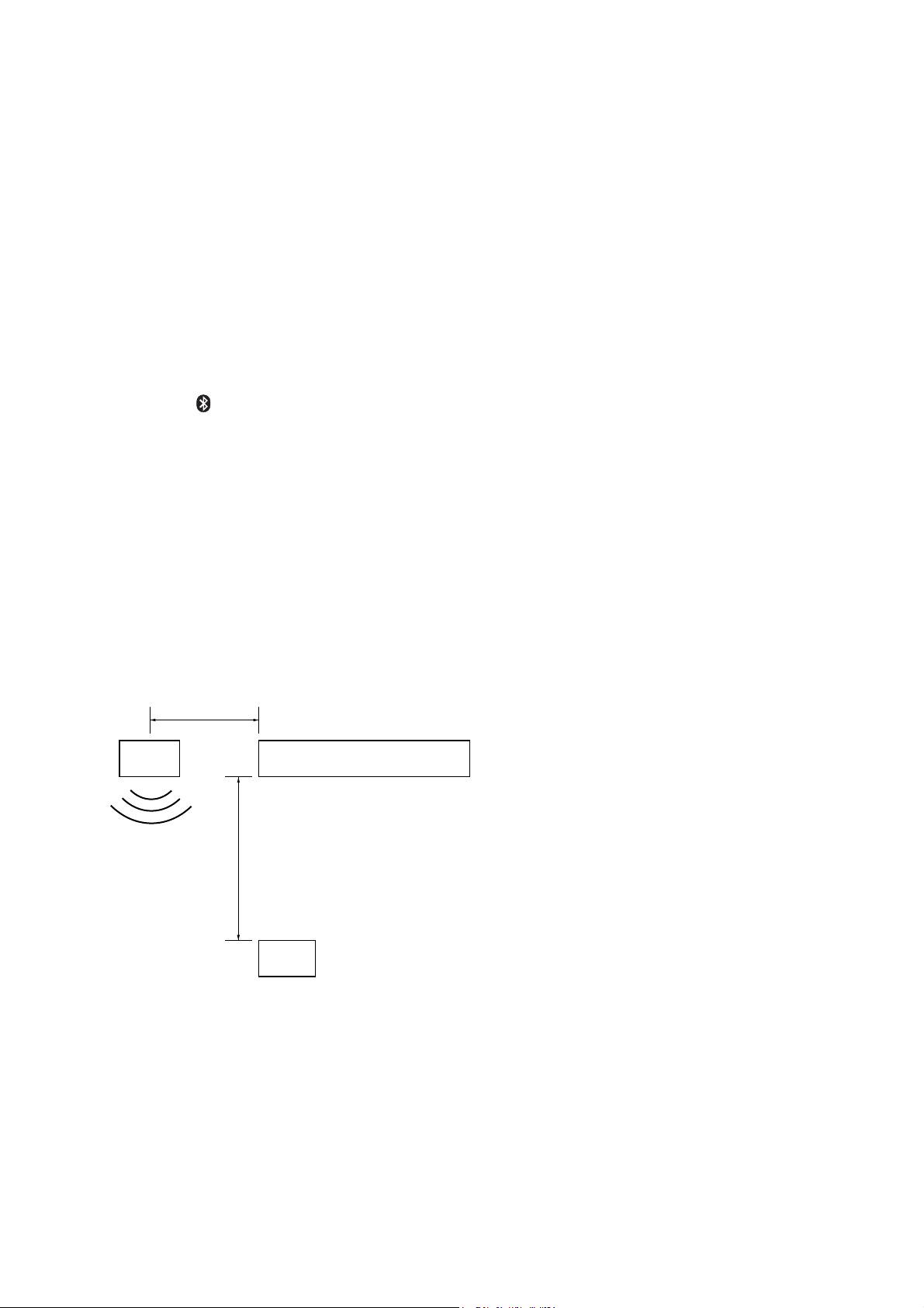
*4Whether in use or not, route the microphone input cord
such that it does not interfere with driving. Secure the cord
with a clamp, etc., if it is installed around your feet.
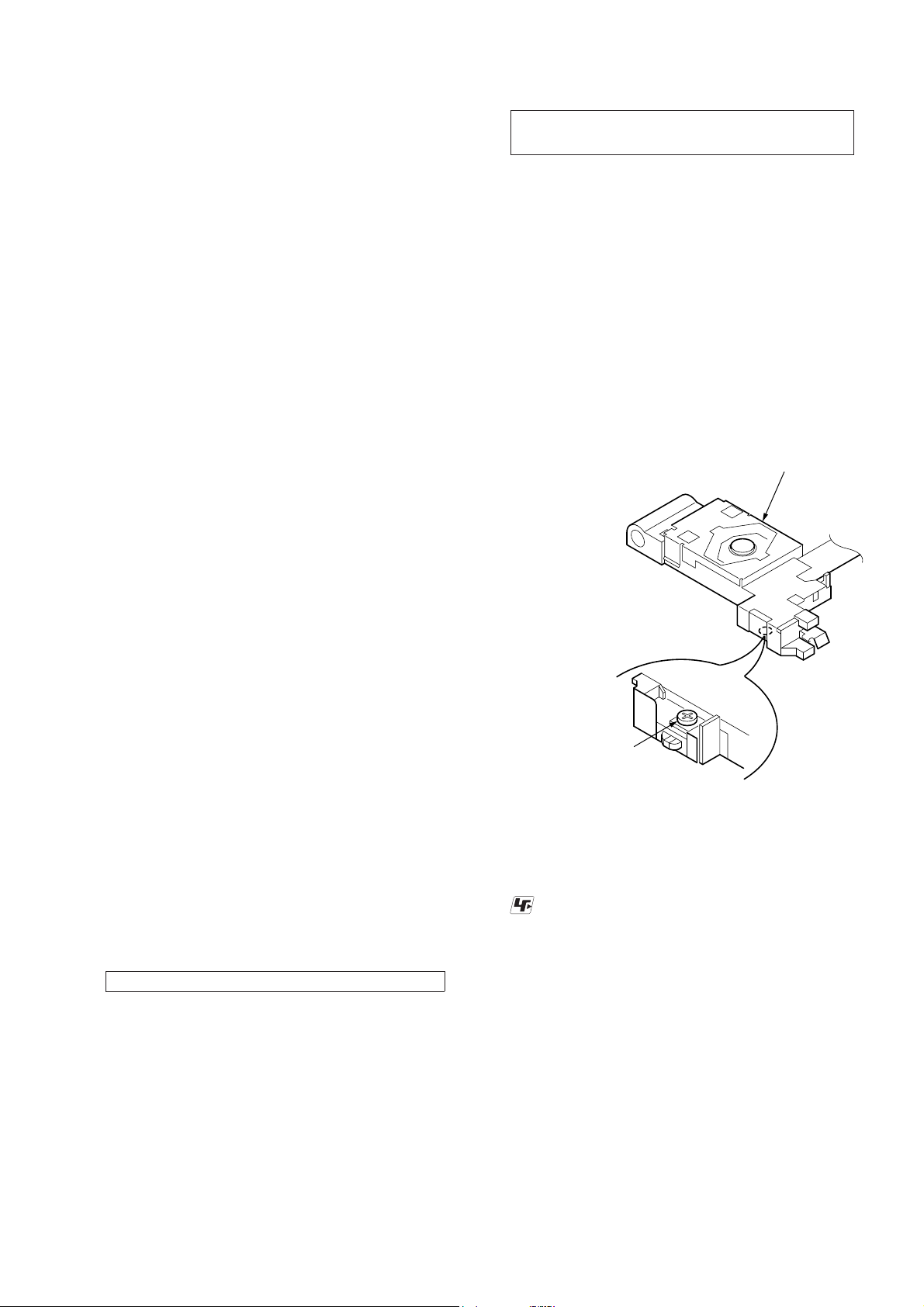
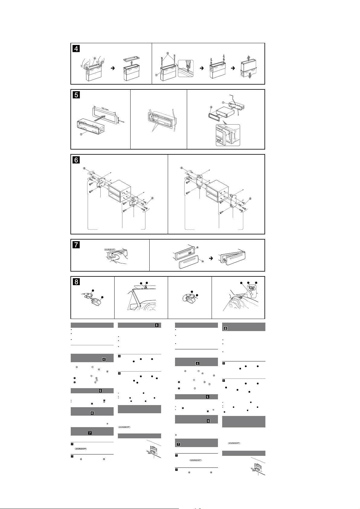
*5For details on installing the microphone, see “Installing
the microphone ( )” on the reverse side.
*1Cordon à broche RCA (non fourni)
*2L’utilisation d’un adaptateur pourrait être nécessaire.
*3non fourni
*4Qu’il soit en usage ou non, acheminez le cordon d’entrée
du microphone de telle sorte qu’il ne gêne pas votre
conduite. Fixez le cordon à l’aide d’une attache, etc., s’il est
installé autour de vos pieds.
*5Pour les détails sur l’installation du microphone,
référez-vous à « Installation du microphone ( ) » au
verso.
Satellite radio tuner
(
SiriusXM
)*3
Syntoniseur radio satellite
(
SiriusXM
)*3
FRONT
AUDIO OUT
SUB OUT (MONO)REAR
AUDIO OUT


 User manual")