Sony MHC-MG110 - Mini Hi-fi Component System User manual

SERVICE MANUAL
9-873-800-13 Sony Corporation
2002E0500-1 Home Audio Company
C2002.05 Published by Sony Engineering Corporation
Ver 1.2 2002.05
MINI Hi-Fi COMPONENT SYSTEM
MHC-MG110/MG310AV
US Model
Canadian Model
MHC-MG110/MG310AV
Mexican Model
MHC-MG110
Australian Model
MHC-MG310AV
• MHC-MG110/MG310AV are composed of following models.
As for the service manual, it is issued for each component model, then, please refer to it.
SPECIFICATIONS
Power requirements
North American model: 120 V AC,60 Hz
Australian model: 220 – 240 V AC,
50/60 Hz
Power consumption
North American model
MHC-MG310AV: 200 watts
MHC-MG110: 150 watts
Australian model
MHC-MG310AV: 200 watts
Dimensions (w/h/d) incl. projecting parts and controls
Approx. 280 ×383 ×480 mm
Mass
MHC-MG310AV: Approx. 11.3 kg
MHC-MG110: Approx. 10.9 kg
Supplied accessories: Remote commander (1)
Batteries (2)
AM loop antenna (1)
FM lead antenna (1)
Rear speaker cords
(MHC-MG310AV only) (2)
Center speaker pads
(attached to the backside of the center
speaker)
(MHC-MG310AV only) (2)
Video cable (Australian model only) (1)
Design and specifications are subject to change without notice.
PARTS LIST
COMPONENT MODEL NAME
MHC-MG110 MHC-MG310AV
COMPACT DISC DECK RECEIVER SYSTEM HCD-MG110 HCD-MG310AV
FRONT SPEAKER SS-MG110 SS-MG510AV
CENTER SPEAKER SS-CT360
REAR SPEAKER SS-RS360
1-476-631-11 REMOTE COMMANDER (RM-SMG5AV) (MG310AV)
1-476-632-11 REMOTE COMMANDER (RM-SMG1) (MG110)
1-501-659-71 ANTENNA (FM) (MG110/MG310AV: US, Canadian)
1-754-060-11 ANTENNA (FM) (Australian)
1-754-102-21 ANTENNA, LOOP (LW.MW)
1-769-433-11 CORD, SPEAKER (10m) (for SS-RS360)
1-823-258-11 CORD, CONNECTION (VIDEO CABLE) (Australian)
4-228-953-01 COVER, BATTERY (for RM-SMG1/SMG5AV)
4-233-902-12 MANUAL, INSTRUCTION (ENGLISH)
4-233-902-22 MANUAL, INSTRUCTION (FRENCH) (Canadian)
4-233-902-31 MANUAL, INSTRUCTION (SPANISH) (Mexican)
Part No. Description Remark

MHC-MG110/MG310AV
REVISION HISTORY
Clicking the version allows you to jump to the revised page.
Also, clicking the version at the upper right on the revised page allows you to jump to the next revised
page.
Ver. Date Description of Revision
1.0 2001.03 New
1.1 2001.05 Addition of Canadian model (MHC-MG110/MG310AV) andAustralian
model (MHC-MG310AV)
1.2 2002.05 Addition of Mexican model (MHC-MG110) (ENG-02011)

SERVICE MANUAL
HC D-MG310AV only
This stereo system is equipped with the Dolby* Pro Logic
Surround decoder.
* Manufactured under license from Dolby Laboratories.
Dolby, Pro Logic, and the double-D symbol ;are
trademarks of Dolby Laboratories. Confidential
unpublished works. '1992-1997 Dolby Laboratories.
All rights reserved.
Amplifier section
U.S.A. models:
AUDIO POWER SPECIFICATIONS
POWER OUTPUT AND TOTAL
HARMONIC DISTORTION:
with 8 ohm loads both channels driven, from
120 – 10,000 Hz; rated 75 watts per channel
minimum RMS power, with no more than 10%
total harmonic distortion from 250 milliwatts to
rated output.
HCD-MG310AV
Front speaker:
Continuous RMS power output
75 + 75 watts
(8 ohms at 1 kHz,
10% THD)
Total harmonic distortion less than 0.09%
(8 ohms at 1 kHz,
40 watts)
Center speaker:
Continuous RMS power output
25 watts
(8 ohms at 1 kHz,
10% THD)
Rear speaker:
Continuous RMS power output
25 + 25 watts
(8 ohms at 1 kHz,
10% THD)
HCD-MG110
Continuous RMS power output
75 + 75 watts
(8 ohms at 1 kHz,
10% THD)
Total harmonic distortion less than 0.09%
(8 ohms at 1 kHz,
40 watts)
Inputs
VIDEO/MD IN (phono jacks):
voltage 250 mV/450 mV,
impedance 47 kilohms
5.1CH (HCD-MG310AV only):
FRONT (phono jacks): voltage 450 mV,
impedance 47 kilohms
REAR (phono jacks): voltage 450 mV,
impedance 47 kilohms
CENTER (phono jack): voltage 450 mV,
impedance 47 kilohms
SUB WOOFER (phono jack):
voltage 450 mV,
impedance 47 kilohms
Outputs
PHONES (stereo phone jack):
accepts headphones of
8 ohms or more
FRONT SPEAKER: accepts impedance of 8 to
16 ohms (except for the
North American model)
SURROUND SPEAKER REAR
(HCD-MG310AV only): accepts impedance of 8 to
16 ohms (except for the
North American model)
SURROUND SPEAKER CENTER
(HCD-MG310AV only): accepts impedance of
8 ohms (except for the
North American model)
SUB WOOFER (HCD-MG310AV only):
voltage 1 V,
impedance 1 kilohm
CD player section
System Compact disc and digital
audio system
Laser Semiconductor laser
(λ = 780 nm)
Emission duration:
continuous
Frequency response 2 Hz – 20 kHz (±0.5 dB)
Wavelength 780 – 790 nm
Signal-to-noise ratio More than 90 dB
Dynamic range More than 90 dB
OPTICAL OUT (CD)
(Square optical connector jack, rear panel)
Wavelength 660 nm
Output Level –18 dBm
US Model
Canadian Model
HCD-MG110/MG310AV
Australian Model
HCD-MG310AV
HCD-MG110/MG310AV
Ver 1.1 2001.06
9-873-801-12 Sony Corporation
2001F0500-1 Home Audio Company
C2001.6 ShinagawaTec Service Manual Production Group
COMPACT DISC DECK RECEIVER
SPECIFICATIONS
HCD-MG110/MG310AV are the Amplifier,CDplayer,Tape
Deck and Tuner section in MHC-MG110/MG310AV.
– Continued on next page –
Model Name Using Similar Mechanism NEW
CD CD Mechanism Type CDM64-K1BD44A
Section Base Unit Name BU-K1BD44A
Optical Pick-up Name KSM-213BFN
TAPE Model Name Using Similar Mechanism NEW
Section Tape Transport Mechanism Type CM8L6Z511A
Photo: HCD-MG110

2
HCD-MG110/MG310AV
TABLE OF CONTENTS
Tape player section
Recording system 4-track 2-channel stereo
Frequency response 40 – 13,000 Hz (±3 dB),
using Sony TYPE I
cassette
Tuner section
FM stereo, FM/AM superheterodyne tuner
FM tuner section
Tuning range 87.5 – 108.0 MHz
Antenna FM lead antenna
Antenna terminals
North American model: 75 ohms unbalanced
Australian model: 75 ohms balanced
Intermediate frequency 10.7 MHz
AM tuner section
Tuning range
North American model: 530 – 1,710 kHz
(with the interval set at
10 kHz)
531 – 1,710 kHz
(with the interval set at
9 kHz)
Australian model: 531 – 1,602 kHz
(with the interval set at
9 kHz)
Antenna AM loop antenna
Antenna terminals External antenna terminal
Intermediate frequency 450 kHz
General
Power requirements
North American model: 120 V AC, 60 Hz
Australian model: 220 – 240 V AC,
50/60 Hz
Power consumption
North American model
HCD-MG310AV: 200 watts
HCD-MG110: 150 watts
Australian model
HCD-MG310AV: 200 watts
Dimensions (w/h/d) incl. projecting parts and controls
Approx. 280 ×383 ×480
mm
Mass
HCD-MG310AV: Approx. 11.3 kg
HCD-MG110: Approx. 10.9 kg
Design and specifications are subject to change
without notice.
1. SERVICING NOTE.................................................. 4
2. GENERAL ................................................................... 5
3. DISASSEMBLY
3-1. Disassembly Flow ........................................................... 7
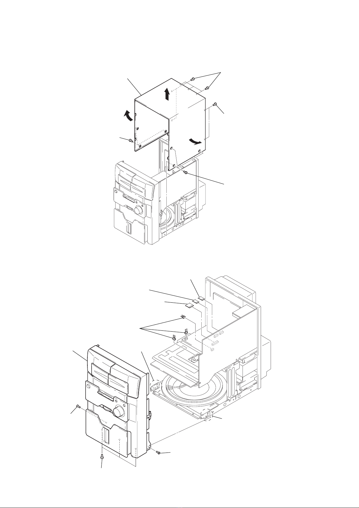
3-2. Upper Cover .................................................................... 8
3-3. Front Block Assy............................................................. 8
3-4. MAIN Board ................................................................... 9
3-5. Back Panel, DC Fan (M391) (Australian model)........... 9
3-6. MAIN AMP Board, POWER Board............................... 10
3-7. Middle (F) Assy, Bracket (Middle-R),
Power Bracket ................................................................. 10
3-8. Mechanism Deck (CDM64-K1BD44A)......................... 11
3-9. Base Unit (BU-K1BD44A)............................................. 11
3-10. BU Holder Assy .............................................................. 12
3-11. Motor Gear Assy (Sled) (M102), CD Board .................. 12
3-12. Op Base Assy (KSM-213BFN) ...................................... 13
3-13. Cassette Lid Assy (A)/(B)............................................... 13
3-14. Mech Deck (TAPE)......................................................... 14
4. TEST MODE.............................................................. 15
5. MECHANICAL ADJUSTMENTS....................... 16
6. ELECTRICAL ADJUSTMENTS
Deck Section ............................................................................. 16
CD Section ................................................................................ 18
7. DIAGRAMS
7-1. Block Diagram –CD SERVO Section –........................ 21
7-2. Block Diagram –TUNER/TAPE DECK Section –...... 22
7-3. Block Diagram –SURROUND Section –...................... 23
7-4. Block Diagram –AMP Section –................................... 24
7-5. Block Diagram
–DISPLAY/POWER SUPPLY Section –...................... 25
7-6. Note for Printed Wiring Boards and
Schematic Diagrams ....................................................... 26
7-7. Schematic Diagram –CD Section –............................... 28
7-8. Printed Wiring Board –CD Section –............................ 29
7-9. Printed Wiring Boards
–CD MOTOR/SENSOR Section –................................ 30
7-10. Schematic Diagram
–CD MOTOR/SENSOR Section –................................ 31
7-11. Printed Wiring Board –TC Section –............................. 32
7-12. Schematic Diagram –TC Section –............................... 33
7-13. Schematic Diagram –MAIN Section (1/4) –................. 34
7-14. Schematic Diagram –MAIN Section (2/4) –................. 35
7-15. Schematic Diagram –MAIN Section (3/4) –................. 36
7-16. Schematic Diagram –MAIN Section (4/4) –................. 37
7-17. Printed Wiring Board –MAIN Section –....................... 38
7-18. Printed Wiring Boards –AMP Section –........................ 40
7-19. Schematic Diagram –AMP Section –............................ 41
7-20. Printed Wiring Boards –DISPLAY Section –............... 42
7-21. Schematic Diagram –DISPLAY Section –.................... 43
7-22. Printed Wiring Board –CONTROL Section –............... 44
7-23. Schematic Diagram –CONTROL Section –.................. 45
7-24. Printed Wiring Boards –POWER Section –.................. 46
7-25. Schematic Diagram –POWER Section –...................... 47
7-26. IC Pin Function Description ........................................... 48
8. EXPLODED VIEWS
8-1. General Section ............................................................... 54
8-2. Front Panel Section ......................................................... 55
8-3. Chassis Section ............................................................... 56
8-4. Mechanism Deck Section (CDM64-K1BD44A) ........... 57
8-5. Base Unit Section (BU-K1BD44A) ............................... 58
9. ELECTRICAL PARTS LIST ............................... 59
Ver 1.1 2001.05

3
HCD-MG110/MG310AV
Fig. A. Using an AC voltmeter to check AC leakage.
1.5 k
Ω
0.15 µF
AC
voltmete
r
(0.75 V)
To Exposed Metal
Parts on Set
Earth Ground
SAFETY CHECK-OUT
After correcting the original service problem, perform the follow-
ing safety check before releasing the set to the customer:
Check the antenna terminals, metal trim, “metallized”knobs,
screws, and all other exposed metal parts for AC leakage.
Check leakage as described below.
LEAKAGE TEST
The AC leakage from any exposed metal part to earth ground and
from all exposed metal parts to any exposed metal part having a
return to chassis, must not exceed 0.5 mA (500 microamperes.).
Leakage current can be measured by any one of three methods.
1. A commercial leakage tester, such as the Simpson 229 or RCA
WT-540A. Follow the manufacturers’instructions to use these
instruments.
2. A battery-operatedAC milliammeter. The Data Precision 245
digital multimeter is suitable for this job.
3. Measuring the voltage drop across a resistor by means of a
VOM or battery-operated AC voltmeter. The “limit”indica-
tion is 0.75 V, so analog meters must have an accurate low-
voltage scale. The Simpson 250 and Sanwa SH-63Trd are ex-
amples of a passive VOM that is suitable. Nearly all battery
operated digital multimeters that have a 2 V AC range are
suitable. (See Fig. A)
CAUTION
Use of controls or adjustments or performance of procedures
other than those specified herein may result in hazardous ra-
diation exposure.
This appliance is classified as a CLASS 1 LASER product.
The CLASS 1 LASER PRODUCT MARKING is located on
the rear exterior.
Laser component in this product is capable of emitting radiation
exceeding the limit for Class 1.
SAFETY-RELATED COMPONENT WARNING!!
COMPONENTS IDENTIFIED BY MARK 0OR DOTTED
LINE WITH MARK 0ON THE SCHEMATIC DIAGRAMS
AND IN THE PARTS LIST ARE CRITICAL TO SAFE
OPERATION. REPLACE THESE COMPONENTS WITH
SONY PARTS WHOSE PART NUMBERS APPEAR AS
SHOWN IN THIS MANUAL OR IN SUPPLEMENTS PUB-
LISHED BY SONY.
The laser diode in the optical pick-up block may suffer electro-
static break-down because of the potential difference generated
by the charged electrostatic load, etc. on clothing and the human
body.
During repair, pay attention to electrostatic break-down and also
use the procedure in the printed matter which is included in the
repair parts.
The flexible board is easily damaged and should be handled with
care.
NOTES ON LASER DIODE EMISSION CHECK
The laser beam on this model is concentrated so as to be focused
on the disc reflective surface by the objective lens in the optical
pick-up block. Therefore, when checking the laser diode emis-
sion, observe from more than 30 cm away from the objective lens.
LASER DIODE AND FOCUS SEARCH OPERATION
CHECK
Carry out the “S curve check”in “CD section adjustment”and
check that the S curve waveforms is output three times.
NOTES ON HANDLING THE OPTICAL PICK-UP
BLOCK OR BASE UNIT
Notes on chip component replacement
•Never reuse a disconnected chip component.
•Notice that the minus side of a tantalum capacitor may be dam-
aged by heat.
Flexible Circuit Board Repairing
•Keep the temperature of the soldering iron around 270 ˚C dur-
ing repairing.
•Do not touch the soldering iron on the same conductor of the
circuit board (within 3 times).
•Be careful not to apply force on the conductor when soldering
or unsoldering.
Ver 1.1 2001.05
ATTENTION AU COMPOSANT AYANT RAPPORT
À LA SÉCURITÉ!
LES COMPOSANTS IDENTIFIÉS PAR UNE MARQUE 0
SUR LES DIAGRAMMES SCHÉMATIQUES ET LA LISTE
DES PIÈCES SONT CRITIQUES POUR LA SÉCURITÉ
DE FONCTIONNEMENT. NE REMPLACER CES COM-
POSANTS QUE PAR DES PIÈCES SONY DONT LES
NUMÉROS SONT DONNÉS DANS CE MANUEL OU
DANS LES SUPPLÉMENTS PUBLIÉS PAR SONY.

4
HCD-MG110/MG310AV SECTION 1
SERVICING NOTES
CD-TEXTTEST DISC
This unit is able to display the test data (character information)
written in the CD on its fluorescent indicator tube.
The CD-TEXT TEST DISC (TGCS-313:4-989-366-01) is used
for checking the display.
To check, perform the following procedure.
Checking Method:
1. Press the I/1button to turn the power on, set the disc to the
disc table with the “test disc” label facing up, and chuck the
disc.
2. Pressthe[CD] buttontosetCDfunction,andpressthe n N button
to playback the disc.
3. The following will be displayed on the liquid crystal display.
Display : 1KHZ/0DB/L R
4. Pressing the [-- ] or [ +] button, select the track. The text
data of each track will be displayed.
Fordetails of the displayed contents for each track, refer to “Table
1: CD-TEXT TEST DISC TEXT Data Contents”.
Restrictions in CD-TEXT Display
In this unit, some special characters will not be displayed prop-
erly. These will be displayed as a space or a character resembling
it.
Table 1: CD-TEXT TEST DISC TEXT Data Contents
(TRACKS No. 1 to 20:Normal Characters)
1 1kHz/0dB/L&R
2 20Hz/0dB/L&R
3 40Hz/0dB/L&R
4 100Hz/0dB/L&R
5 200Hz/0dB/L&R
6 500Hz/0dB/L&R
7 1kHz/0dB/L&R
8 5kHz/0dB/L&R
9 7kHz/0dB/L&R
10 10kHz/0dB/L&R
11 16kHz/0dB/L&R
12 18kHz/0dB/L&R
13 20kHz/0dB/L&R
14 1kHz/0dB/L&R
15 1kHz/–1dB/L&R
16 1kHz/–3dB/L&R
17 1kHz/–6dB/L&R
18 1kHz/–10dB/L&R
19 1kHz/–20dB/L&R
20 1kHz/–60dB/L&R
TRACK
No. Displayed Contents
Note: Track No. 21 to 99 are not displayed.
.>
CLEANING OBJECTIVE LENS OF OPTICAL PICK-UP
• In cleaning the objective lens of optical pick-up, be sure the
following below.
(Figure A)
Note 1. In cleaning the lens, do not apply an excessive force.
As the optical pick-up is vulnerable, application of excessive
force could damage the lens holder.
Note 2. In cleaning, do not use a cleaner other than exclusive cleaning
liquid (KK-91 or isopropyl alcohol).
Note 3. Wipe the objective lens spirally from center toward outside. (See
Figure A)
2Remove the
magnet assy.
1Open the torsion holder
(magnet) in direction of
arrow A.
A
optical pick-up
bracket (top 60) hole
3Put a cotton bud into
the hole on the bracket
(top 60) and clean the
OP lens.
Ver 1.1 2001.05
MODEL IDENTIFICATION
– REAR VIEW –
MODEL NO.HCD-MG[][][][][]
COMPACT DISC DECK RECEIVER
MADE IN CHINA
US, Canadian models: AC: 120V 60Hz
Australian Model: AC: 220–240V-50/60H
z

5
HCD-MG110/MG310AV
SECTION 2
GENERAL This section is extracted from
instruction manual.
4
Parts Identification
5.1CH/VIDEO (MD)* 5(28)
AUDIO IN L jack wk (29)
AUDIO IN R jack wj (29)
CD 5(14, 21)
CD SYNCHRO wh (21, 22)
CLEAR w; (15, 19, 34)
Deck A es (20)
Deck B 0(20)
DIRECTION ea (20)
DISC ACCESS ql (12, 21)
Display window 4
DISPLAY wd (12, 17, 19, 34)
ENTER qk (11, 15, 18, 22, 26, 28)
FRONT* qd (25)
GAME e; (26, 29)
KEYBOARD INPUT jack ws
(27)
LINK* qg (25)
MENU ea (16, 18)
PHONES jack wa
PLAY MODE wf (14, 22)
PRESET EQ 7(24)
PRO LOGIC* qs (11, 25)
PUSH OPEN (Front cover) qj
(12)
REAR* qf (25)
REC PAUSE/START wh (21,22)
REPEAT wg (14)
STEREO/MONO wg (19)
SURROUND* qa (25)
SURROUND MODE 8(25)
TAPE A/B 5(20)
TIMER SELECT 3(23, 27)
TIMER SET 3(11, 23, 26)
TUNER/BAND 5(18)
VIDEO IN jack wl (29)
VIDEO (MD)** 5(28)
VOLUME control qh
BUTTON DESCRIPTIONS
Z(deck A) 1
=/1 (power) 2
m(rewind) 6
nN(play) 6
XPAUSE 6
M(fast forward) 6
x(stop) 6
—.(go back) 6
>+ (go forward) 6
Z(deck B) 9
* HCD-MG310AV only
** HCD-MG110 only
The items are arranged in alphabetical order.
Refer to the pages indicated in parentheses ( ) for details.
Main unit
1
es
ea
e;
wl
wk
wj
wh
wg
wf
wd
ws
wa
234 567 8 9
qs
w; ql
qd
0
qa
qf
qg
qh
qj
qk

6
HCD-MG110/MG310AV
Setting the time
1Turn on the system.
2Press TIMER SET.
When you set the clock for the first time, go
to step 5.
3Press — .or > + repeatedly to
select CLOCK SET.
4Press ENTER.
5Press — .or > + repeatedly to set
the hour.
6Press ENTER.
7Press — .or > + repeatedly to set
the minute.
8Press ENTER.
Tip
If you made a mistake or want to change the time,
start over from step 1.
Note
The clock settings are canceled when you disconnect
the power cord or if a power failure occurs.
Remote Control
For HCD-MG310AV
qg
qh
ql
qk
qj
w;
1234
wa
ws
wd
wf
6
7
8
9
5
qf
0
qd
qa
qs
5.1CH wa (30)
CD ql (14, 21)
CENTER +/–5(11)
DBFB qd (24)
DISPLAY 9(12, 17, 19)
GAME 8(26, 29)
GROOVE qf (24)
PLAY MODE 2(14, 22)
PRESET EQ qk (24)
PRO LOGIC wf (11, 25)
REAR +/–6(11)
REPEAT 3(14)
SCROLL qa (17)
SLEEP 1(26)
SURROUND qh (25)
TAPE A/B w; (20)
TEST TONE ws (11)
TUNER/BAND 7(18)
VIDEO (MD) wd (28)
VOL +/–qg
BUTTON DESCRIPTIONS
@/1 (power) 4
N(play) 0
X(pause) 0
x(stop) 0
.(go back) 0
m(rewind) 0
M(fast forward) 0
>(go forward) 0
TDISC/DISCtqs qj
CD wf (14, 21)
CLOCK/TIMER SELECT 2
(23, 27)
CLOCK/TIMER SET 3(23, 26)
DBFB qg (24)
DISPLAY wh (12, 17, 19)
ENTER 5(11, 15, 18, 22, 26,
28, 34)
GAME 7(26, 29)
GROOVE qh (24)
PLAY MODE wg (14, 22)
PRESET EQ w; (24)
REPEAT 8(14)
BUTTON DESCRIPTIONS
@/1 (power) 4
N(play) 0
X(pause) 0
x(stop) 0
.(go back) wa
m(rewind) ws
M(fast forward) qa
>(go forward) qs
TDISC/DISCtqf ql
For HCD-MG110
6
7
8
9
5
qf
qg
qh
0
qd
qa
qs
ql
qk
qj
w;
1234
wa
ws
wd
wh
wg
wf
SCROLL qd (17)
SLEEP 1(26)
SURROUND qk (25)
TAPE A/B wd (20)
TUNER/BAND 9(18)
VIDEO (MD) 6(28)
VOL +/–qj

HCD-MG110/MG310AV
7
• This set can be disassembled in the order shown below.
3-1. DISASSEMBLY FLOW
SECTION 3
DISASSEMBLY
3-2. UPPER COVER
(Page 8)
3-3. FRONT BLOCK ASSY
(Page 8)
3-4. MAIN BOARD
(Page 9)
3-5. BACK PANEL,
DC FAN (M391)
(Australian model)
(Page 9)
3-6. MAIN AMP BOARD,
POWER BOARD
(Page 10)
3-13. CASSETTE LID ASSY (A)/(B)
(Page 13)
SET
3-10. BU HOLDER ASSY
(Page 12)
3-12. OP BASE ASSY
(KSM-213BFN)
(Page 13)
3-11. MOTOR GEAR ASSY
(SLED) (M102),
CD BOARD
(Page 12)
3-14. MECH DECK (TAPE)
(Page 14)
3-7. MIDDLE (F) ASSY,
BRACKET (MIDDLE-R),
POWER BRACKET
(Page 10)
3-8. CD MECHANISM DECK
(CDM64-K1BD44A)
(Page 11)
3-9. BASE UNIT
(BU-K1BD44A)
(Page 11)
Ver 1.1 2001.05

HCD-MG110/MG310AV
8
3-3. FRONT BLOCK ASSY
Note: Follow the disassembly procedure in the numerical order given.
3-2. UPPER COVER
1
three screws
(BVTP3
×
8)
2
five screws
(BVTP3
×
8)
2
two screws
(BVTP3
×
8)
3
upper cover
1
three screws
(BVTP3
×
8)
5
two bosses
4
screw (KTP3
×
8)
3
three screws
(BVTP3
×
8)
4
screw (KTP3
×
8)
6
front block assy
5
two bosses
2
three connectors
(CN310, 503, 803)
1
wire (flat type) (10 core)
(CN311)
1
wire (flat type) (11 core)
(CN312)
1
wire (flat type) (17 core)
(CN301)
Ver 1.1 2001.05

HCD-MG110/MG310AV
9
3-4. MAIN BOARD
3-5. BACK PANEL, DC FAN (M391) (Australian model)
3
three screws
(BVTP3
×
8)
3
three screws
(BVTP3
×
8)
3
screw (BVTP3
×
8)
3
screw
(BVTP3
×
8)
MG310AV
MG310AV
MG110
4
screw
(BVTP3
×
8)
5
MAIN board
1
wire (flat type) (21 core)
(CN303)
1
wire (flat type) (18 core)
(CN309)
2
two connectors
(CN304, 903)
2
two connectors
(CN305, 317)
2
connector
(CN313)
5
back panel
1
two screws
(BVTP3
×
10)
1
two screws
(BVTP3
×
10)
1
eleven screw
s
(BVTP3
×
10)
MG310AV
3
four screws
(BVTP3
×
10)
(Australian model)
4
DC fan (M391)
(Australian model)
2
Ver 1.1 2001.05

HCD-MG110/MG310AV
10
3-6. MAIN AMP BOARD, POWER BOARD
3-7. MIDDLE (F) ASSY, BRACKET (MIDDLE-R), POWER BRACKET
5
center bracket
4
three screws
(BVTP3
×
8)
2
two screws
(BVTP3
×
8)
1
connector
(CN502)
3
MAIN AMP board
7
POWER board
6
two screws
(BVTP4
×
8
)
6
two screws
(BVTP4
×
8)
2
four screws
(BVTP3
×
8)
3
middle (F) assy
1
screw (BVTP3
×
8)
2
screw (BVTP3
×
8)
4
three screws
(BVTP3
×
8)
6
bracket (middle-R)
5
two screws
(BVTP3
×
8)
9
two screws
(BVTP3
×
8)
7
screw
(BVTP3
×
8)
2
screw
(BVTP3
×
8)
0
power bracket
8
three screws
(BVTP3
×
8)

HCD-MG110/MG310AV
11
3-8. CD MECHANISM DECK
(CDM64-K1BD44A)
3-9. BASE UNIT
(BU-K1BD44A)
2
table (60)
lower chassis
1
screw (2.6
×
8)
5
CD mechanism deck
(CDM64-K1BD44A)
4
two screws
(BVTP3
×
8
)
3
screw
(PSW3
×
6)
4
four screws
(BVTP3
×
8)
4
four screws
(BVTP3
×
8)
1
three screws
(BVTP3
×
8)
2
bracket (top 60)
3
base unit
(BU-K1BD44A)

HCD-MG110/MG310AV
12
3-10. BU HOLDER ASSY
3-11. MOTOR GEAR ASSY (SLED) (M102), CD BOARD
4
BU holder assy
1
tension spring (F1)
2
tension spring (F-2)
3
two screws
(PTP2.6
×
8
)
3
two screws
(PTP2.6
×
8)
1
Remove two
solders.
qd
CD board
2
two screws
(P2
×
3)
6
claw
8
claw
8
two claws
9
gear cover
7
gear
0
gear
5
parallel (FFC) (16 core) wire
(CN102)
qs
motor gear assy (SLED)
(M102)
3
screw (P2
×
5)
qa
Remove two solders.
4

HCD-MG110/MG310AV
13
3-12. OP BASE ASSY
(KSM-213BFN)
3-13. CASSETTE LID ASSY (A) / (B)
2
sled shaft
1
Slide the lever
in the direction of arrow
A
.
3
Remove the optical pick-up
(KSM-213BFN) in the directio
n
of arrow
B
.
A
B
5
cassette li
d
assy (B)
3
cassette lid
assy (A)
2
two claws
4
two claws
1
Open the cassette lid
assy (A)/(B).

HCD-MG110/MG310AV
14
3-14. MECH DECK (TAPE)
4
cassette holder assy (A)
0
two screws
(BVTP2.6)
1
three screws
(BVTP3
×
10)
qs
mech deck (TAPE)
qa
MD bracket
2
two screws
(BVTP3
×
10
)
9
TC board
8
screw (BVTP2.6)
6
two screws
(BVTP2.6)
7
shield plate (MD)
5
cassette
holder
assy (B)
3

15
HCD-MG110/MG310AV
SECTION 4
TEST MODE
Ver 1.1 2001.05
[MC Cold Reset]
• The cold reset clears all data including preset data stored in the
RAM to initial conditions. Execute this mode when returning
the set to the customer.
Procedure:
1. Turn the power ON or set to the DEMO mode.
2. Press three buttons of x, [CLEAR], and [DISPLAY] simul-
taneously.
3. The set is reset, and becomes DEMO mode.
[Change-over the AMTuning Interval]
(EXCEPT AEP, UK, and Saudi Arabia models)
• The AM tuning interval can be changed over 9 kHz or 10 kHz.
Procedure:
1. Press the I/1button to turn the power ON.
2. Select the function “TUNER”, and press the [TUNER/BAND]
button to select the BAND “AM”.
3. Press the I/1button to turn the power OFF.
4. Press the [ENTER] and I/1buttons simultaneously to the tun-
ing interval is changed over.
[CD Delivery Mode and RAM Initialize]
• This mode moves the optical pick-up to the position durable
to vibration, and initializes the RAM. Use this mode when return-
ing the set to the customer after repair.
Procedure:
1. Press the I/1button to turn the power ON.
2. Press three buttons of [ENTER],M, and [CLEAR] simul-
taneously.
3. The set is turn the power off and initializes the RAM auto-
matically.A message “LOCK” is displayed on the fluorescent
indicator tube, and the CD delivery mode is set.
[LED and Fluorescent Indicator Tube All Lit, Key
Check Mode]
Procedure:
1. Press three buttons of x, [MENU], and [DISPLAY] simulta-
neously.
2. LEDs and fluorescent indicator tube are all turned on.
3. Press the [MENU] button and go to the version display mode.
Press the mbutton and go to the key and jog test mode.
4. To release from these mode, press three buttons in the same
manner as step 1, or disconnect the power cord.
– Version display mode –
Press the – .button to display the version .
– Key and jog test mode –
In the key check mode, the fluorescent indicator tube displays
“K 0 J0 V0”. Each time a button is pressed, “K” value in-
creases. However, once a button is pressed, it is no longer taken
into account.
“J” value increases like 1, 2, 3 ... if turn the [DISC ACCESS]
dial clockwise, or it decreases like 0, 9, 8 ... if turn the
[DISC ACCESS] dial counterclockwise.
“V” value increases like 1, 2, 3 ... if turn the [VOLUME] knob
clockwise, or it decreases like 0, 9, 8 ... if turn the [VOLUME]
knob counterclockwise.
[CD Service Mode]
• This mode can run the CD sled motor optionally. Use this mode,
for instance, when cleaning the optical pick-up.
Procedure:
1. Press the I/1button to turn the power ON.
2. Select the function “CD”.
3. Press three buttons of [ENTER],M, and [REPEAT] simul-
taneously.
4. Set to the Sled Servo mode.
5. With the CD in stop status, press the Mbutton to move the
optical pick-up to outside track and display “SLED OUT”, or
press the mbutton to move the optical pick-up to inside
track and display “SLED IN”.
6. To exit from this mode, perform as follows.
1) Move the optical pick-up to the most inside track.
2) Press three buttons of x, [CLEAR], and [DISPLAY]
simultaneously. (cold reset)
Notes: • Always move the optical pick-up to most inside track when
exiting from this mode. Otherwise, a disc will not be unloaded.
• Do not run the sled motor excessively, otherwise the gear can
be chipped.

16
HCD-MG110/MG310AV
SECTION 5
MECHANICAL ADJUSTMENTS
•TAPE MECHANISM DECK SECTION
Precaution
1. Clean the following parts with a denatured alcohol-moistened
swab:
record/playback heads pinch rollers
erase head rubber belts
capstan idlers
2. Demagnetize the record/playback head with a head demagne-
tizer.
3. Do not use a magnetized screwdriver for the adjustments.
4. After the adjustments, apply suitable locking compound to the
parts adjusted.
5. The adjustments should be performed with the rated power
supply voltage unless otherwise noted.
Torque Measurement
2.94 mN • m to 7.84 mN • m
31 to 71 g • cm
(0.43 – 0.98 oz • inch)
0.14 mN • m to 0.59 mN • m
2 to 6 g • cm
(0.02 – 0.08 oz • inch)
2.94 mN • m to 7.84 mN • m
31 to 71 g • cm
(0.43 – 0.98 oz • inch)
0.14 mN • m to 0.59 mN • m
2 to 6 g • cm
(0.02 – 0.08 oz • inch)
6.86 mN • m to 17.64 mN • m
71 to 143 g • cm
(0.98 – 1.99 oz • inch)
more than 0.98 N • m
100 g or more
(3.53 oz or more)
more than 0.98 N • m
100 g or more
(3.53 oz or more)
Mode Torque meter
CQ-102C
CQ-102C
CQ-102RC
CQ-102RC
CQ-201B
CQ-403A
CQ-403R
Meter reading
FWD
FWD
back tension
REV
REV
back tension
FF/REW
FWD tension
REV tension
Ver 1.1 2001.05 SECTION 6
ELECTRICAL ADJUSTMENTS
Precaution
1. Demagnetize the record/playback head with a head demagne-
tizer.
2. Do not use a magnetized screwdriver for the adjustments.
3. After the adjustments, apply suitable locking compound to the
parts adjust.
4. The adjustments should be performed with the rated power
supply voltage unless otherwise noted.
5. The adjustments should be performed in the order given in
this service manual. (As a general rule, playback circuit ad-
justment should be completed before performing recording
circuit adjustment.)
6. The adjustments should be performed for both L-CH and R-
CH.
7. Switches and controls should be set as follows unless other-
wise specified.
8. Set to the DOLBY NR OFF.
• Test Tape
Tape Signal Used for
P-4-A100 10 kHz, – 10 dB Azimuth Adjustment
WS-48A 3 kHz, 0 dB Tape Speed Check
0 dB = 0.775 V
DECK SECTION

17
HCD-MG110/MG310AV
Tape Speed Check DECK B
Mode: Playback
1. Insert the WS-48A into the deck B.
2. Press the nN button on the deck B.
3. Confirm that the frequency counter reads 3,000 ±60 Hz.
Sample value of Wow and Flutter: 0.3% or less W.RMS (JIS)
(WS-48A)
2. Turn the adjustment screw and check output peaks. If the peaks
do not match for L-CH and R-CH, turn the adjustment screw
so that outputs match within 1dB of peak.
3. Mode: Playback
4. Repeat step 1 to 3 in playback (REV) mode.
5. After the adjustments, apply suitable locking compound to the
parts adjusted.
Screw
position
L-CH
peak
within
1dB
Output
level
L-CH
peak
R-CH
peak
within
1dB
Screw
position
R-CH
peak
set
test tape
P-4-A100
(10 kHz, – 10 dB)
R-CH
oscilloscope
L-CH
R-CH
VH
waveform of oscilloscope
in phase 45 °90°135 °180°
good wrong
MAIN AMP board
FRONT SPEAKER terminal (J501
)
L-CH
+
–
set
test tape
WS-48A
(3 kHz, 0 dB)
MAIN AMP board
FRONT SPEAKER terminal (J501)
L-CH, R-CH
frequency counter
Record/Playback Head Azimuth Adjustment
Note: Perform this adjustments for both decks
Procedure:
1. Mode: Playback (FWD)
DECK A DECK B
set
MAIN AMP board
FRONT SPEAKER terminal (J501)
L-CH, R-CH
+
–
level meter
test tape
P-4-A100
(10 kHz, –10 dB)
Adjustment Location:Playback Head (Deck A).
Record/Playback/Erase Head (Deck B).
reverse
forward
Ver 1.1 2001.05

18
HCD-MG110/MG310AV
Ver 1.1 2001.05
CD SECTION
Note:
1. CD Block is basically designed to operate without adjustment. There-
fore, check each item in order given.
2. Use PATD-012 disc (4-225-203-01) unless otherwise indicated.
3. Use an oscilloscope with more than 10MW impedance.
4. Clean the object lens by an applicator with neutral detergent when the
signal level is low than specified value with the following checks.
S Curve Check
Connection:
Procedure:
1. Connect an oscilloscope to test pointTP (FEI) and TP (VC) on
the CD board.
2. Turn the power on.
3. Put the disc (PATD-012) in and turned power switch on again
and actuate the focus search. (actuate the focus search when
disc table is moving in and out)
4. Check the oscilloscope waveform (S-curve) is symmetrical
betweenA and B.And confirm peak to peak level within 2 ±1
Vp-p.
S-curve waveform
Note: • Try to measure several times to make sure than the ratio of A : B
or B : A is more than 10 : 7.
• Take sweep time as long as possible and light up the
brightness to obtain best waveform.
Checking Location: CD board
RFDC Level Check
Connection:
Procedure:
1. Connect an oscilloscope to test pointTP (RFDC) and TP (VC)
on the CD board.
2. Turn the power on.
3. Put the disc (PATD-012) in to playback the number two track.
4. Confirm that oscilloscope waveform is clear and check RFDC
signal level is correct or not.
Note: A clear RFDC signal waveform means that the shape “◊” can be
clearly distinguished at the center of the waveform.
+
–
CD board
TP (FE)
TP (VC)
oscilloscope
A
B
symmetry
within 2 ±1 Vp-p
+
–
CD board
TP (RFDC)
TP (VC)
oscilloscope
VOLT/DIV: 200 mV
TIME/DIV: 500 ns
level: 1.15 ±0.35 Vp-p
RFDC signal waveform
Checking Location: CD board
RFAC Level Check
Connection:
Procedure:
1. Connect an oscilloscope to test point TP (RFAC) andTP (VC)
on the CD board.
2. Turn the power on.
3. Put the disc (PATD-012) in to playback the number two track.
4. Confirm that oscilloscope waveform is clear and check RFAC
signal level is correct or not.
Note: A clear RFAC signal waveform means that the shape “◊” can be
clearly distinguished at the center of the waveform.
RFAC signal waveform
Checking Location: CD board
+
–
CD board
TP (RFAC)
TP (VC)
oscilloscope
VOLT/DIV: 200 mV
TIME/DIV: 500 ns
level: 1.35 ±0.4 Vp-p
This manual suits for next models
7
Table of contents
Other Sony Stereo System manuals

Sony
Sony CMT-NEZ33 User manual

Sony
Sony MEX-BT3850U Product guide

Sony
Sony MHC-EC78Pi - Mini Hi-fi Component System User manual

Sony
Sony SEN-421CD User manual

Sony
Sony HCD-RG55 User manual

Sony
Sony HCD-XB8KW User manual

Sony
Sony HCD-VP700 User manual

Sony
Sony GTK-XB72 Reference guide

Sony
Sony MHC-NX1 User manual

Sony
Sony CMT-CP1 - Micro Hi Fi Component System User manual