Sony SRS-X88 User manual

SERVICE MANUAL
Sony Corporation
Published by Sony Techno Create Corporation
SRS-X88
SPECIFICATIONS
PERSONAL AUDIO SYSTEM
9-896-161-02
2015F33-1
© 2015.06
US Model
Canadian Model
AEP Model
UK Model
E Model
Australian Model
Chinese Model
Ver. 1.1 2015.06
Note:
Be sure to keep your PC used for service and
checking of this unit always updated with the
latest version of your anti-virus software.
In case a virus affected unit was found during
service, contact your Service Headquarters.
Section for Speaker
Speakers
Super tweeter: Approx. 20 mm
(13/16 inches) diameter × 2
Midrange: Approx. 40 mm (15/8inches)
diameter × 2
Subwoofer: Approx. 69 mm (2 3/4inches)
diameter × 1
Section for Amplier
POWEROUTPUTANDTOTAL HARMONIC
DISTORTION:
Power Output (reference)
harmonic distortion, 10 kHz)
Midrange: 15 W × 2 (at less than 10 %
harmonic distortion, 1 kHz)
Subwoofer: 30 W (at less than 10 %
harmonic distortion, 100 kHz)
Section for Network
Compatiblestandards
IEEE 802.11 a/b/g/n (WEP 64 bit,
WEP 128 bit, WPA/WPA2-PSK (AES), WPA/
WPA2-PSK (TKIP))
Radio frequency
2.4/5 GHz band
Section for BLUETOOTH
Output
BLUETOOTH Specification Power Class 2
Maximum communication range
Line of sight Approx. 10 m (about 30 ft)*
Radio frequency
2.4 GHz band (2.4000 GHz – 2.4835 GHz)
Communication System
BLUETOOTH Specification Version 3.0
Compatible BLUETOOTH Proles* 2
A2DP (Advanced Audio Distribution
Control Profile)
Supported codec* 3
Profile) /AVRCP (Audio Video Remote
SBC*4/ AAC*5/ LDAC* 6
Transmission bandwidth(A2DP)
20 Hz – 20,000 Hz (with 44.1 kHz sampling)
*1The actual range will vary depending on factors
such as obstacles between devices, magnetic
fields around a microwave oven, static
electricity, reception sensitivity, aerial’s
performance, operating system, software
application, etc.
*2BLUETOOTH standard profiles indicate the
purpose of BLUETOOTH communication
between devices.
*3Codec: Audio signal compression and
conversion format
*4Subband Codec
*5Advanced Audio Coding
Section for USB port
USB A port ( A)
You can connect a USB flash drive,
Walkman®, or iPhone/iPad/iPod that is
compatible with this unit.
Supported format*1
MP3: 32/44.1/48 kHz, 16 - 320 kbps (CBR/
VBR)
AAC: 32/44.1/48/88.2/96 kHz, 16 - 320 kbps
(CBR/VBR)
WMA: 32/44.1/48 kHz, 16 - 320 kbps (CBR/
VBR)
WAV: 32/44.1/48/88.2/96/176.4/192 kHz (16/
24 bit)
AIFF: 32/44.1/48/88.2/96/176.4/192 kHz (16/
24 bit)
FLAC: 32/44.1/48/88.2/96/176.4/192 kHz
(16/24 bit)
ALAC: 32/44.1/48/88.2/96/176.4/192 kHz
(16/24 bit)
DSD (DSF/DSDIFF): 2.8 MHz (1 bit)
Transferspeed
High-speed
Supported USB device
Mass Storage Class (MSC)
Maximum output current
2.1 A MAX
USB B port( B)
You can connect a compatible device such
as a PC, etc., to this unit using a USB cable
(not supplied).
Supported format*1
PCM: 44.1/48/88.2/96/176.4/192 kHz (16/
24/32bit)
DSD (DSF/DSDIFF): 2.8 MHz (1bit)
*1Compatibility with all encoding/writing
software, recording devices and recording
media cannot be guaranteed.
General
AUDIO IN
Networkport
10BASE-T/100BASE-TX (Auto Polarity)
Power
DC 19.5 V (using the supplied AC adaptor
connected to AC 100V-240V, 50Hz/60Hz
power supply)
Power consumption
45 W
Power consumption (during standby mode)
Less than 0.5 W
Power consumption (during BLUETOOTH/
networkstandby mode)
Less than 6 W
Operating temperature
5 °C to 35 °C (41 °F to 95 °F)
Dimensions (w/h/d) (including projecting parts
and controls)
Approx. 359 mm × 111 mm × 103 mm (141/4
inches × 4 3/8inches × 4 1/8inches)
Mass
Approx. 2.7 kg (5 lb 15 oz)
Supplied accessories:
Remote control (RMT-CX9) (1)
AC adaptor (VGP-AC19V75) (1)
AAA size batteries for the remote control (2)
(for trial use)
Speaker grille detach tool (1)
Wi-Fi Startup Guide
Operating Instructions, Warranty card
Warranty card (for customers in Canada) (1)
ANALOG 3.5 mm stereo mini jack
AC power cord (mains lead) (2) (AEP, UK)
(US, CND)
Operating Instructions (Other models)
(US, CND)
For customers in the UK, Ireland, Malta,
Cyprus, and Hong Kong:
Use the AC power cord (mains lead) (A).
For safety reasons, the AC power cord
(mains lead) (B) is not intended for the
above countries/regions and shall therefore
not be used there.
For customers in other countries/regions:
Use the AC power cord (mains lead) (B).
The AC power cord (mains lead) (B) is not
supplied for customers in Hong Kong.
Design and specifications are subject to
change without notice.
(A)
(B)
Super tweeter: 15 W × 2 (at less than 10 %
*6LDAC is an audio coding technology developed
by Sony that enables the transmission of High-
Resolution (Hi-Res) Audio content, even over a
BLUETOOTH connection. Unlike other
BLUETOOTH compatible coding technologies
such as SBC, it operates without any down-
conversion of the Hi-Res Audio content*7, and
allows approximately three times more data*8
than those other technologies to be transmitted
over a BLUETOOTH wireless network with
unprecedented sound quality, by means of
efficient coding and optimized packetization.
*7Excluding DSD format contents
*8In comparison with SBC (Subband Coding) when
the bitrate of 990kbps (96/48kHz) or 909kbps
(88.2/44.1kHz) is selected
Plug adaptor* 2(1) (LA, SP5)
AC power cord * 1(1) (Other models)
Warranty card* 2(1) (AEP, UK, AUS, KR)
*1The included number of items varies depending
on the country/region.
*2This item is not included in some countries/
regions.
1
• For Remote control

SRS-X88
2
1. SERVICING NOTES ............................................. 3
2. DISASSEMBLY
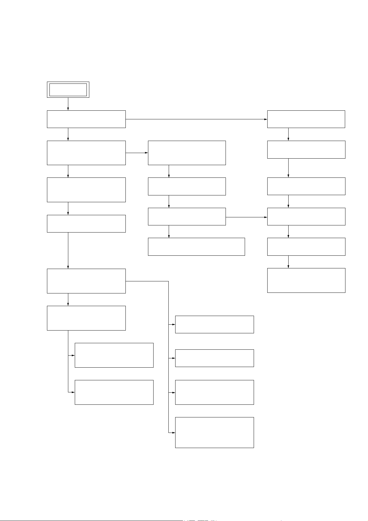
2-1. Disassembly Flow........................................................... 9
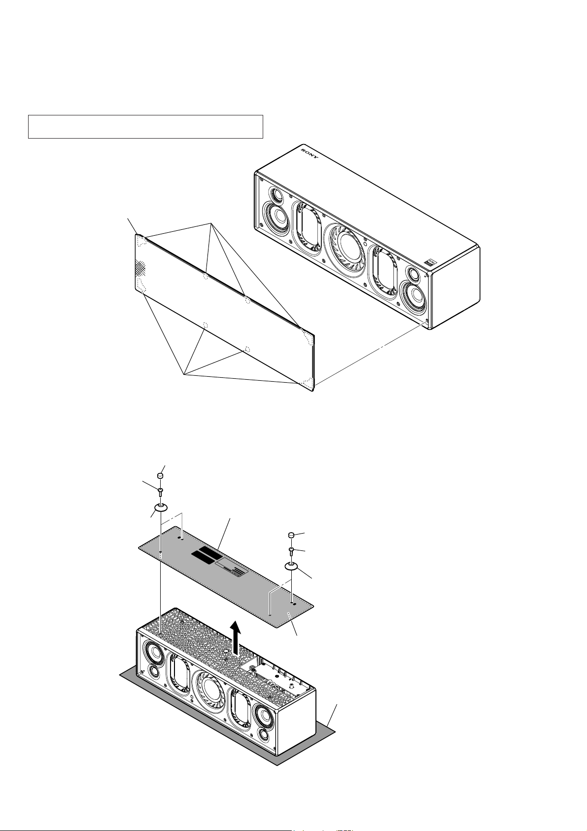
2-2. Grille Sub Assy ............................................................... 10
2-3. Bottom Sub Assy ............................................................ 10
2-4. Baffle Block, Rear Cabinet Block................................... 11
2-5. Speaker Wire (R-ch), Subwoofer Wire........................... 12
2-6. Speaker Wire (L-ch)........................................................ 13
2-7. RC/LED Board Block, Window (IR).............................. 14
2-8. RC Board ........................................................................ 15
2-9. LED Board...................................................................... 15
2-10. Box (Lch, Rch) Block, O Ring (LED)............................ 16
2-11. Super Tweeter (2 cm) (SP6, SP7) ................................... 17
2-12. Loudspeaker (4 cm) (Midrange) (SP4, SP5) .................. 18
2-13. Subwoofer (69 mm) (SP1).............................................. 19
2-14. Loudspeaker (74 × 48 mm) Passive (SP2, SP3) ............. 19
2-15. Bluetooth Module (BT1) ................................................ 20
2-16. Heat Sink (Upper)........................................................... 21
2-17. Card WLAN/BT Combo................................................. 22
2-18. JACK Board.................................................................... 23
2-19. MAIN Board Block-1 ..................................................... 24
2-20. MAIN Board Block-2 ..................................................... 25
2-21. MAIN Board Block-3 ..................................................... 27
2-22. NETWORK Board, MAIN Board .................................. 28
2-23. Antenna Sub Assy (ANT1) ............................................. 28
3. TEST MODE ............................................................ 29
4. EXPLODED VIEWS
4-1. Overall Section ............................................................... 32
4-2. Subwoofer Section.......................................................... 33
4-3. Super Tweeter Section .................................................... 34
4-4. Network Section ............................................................. 35
4-5. Main Section ................................................................... 36
4-6. Rear Cabinet Section ...................................................... 37
5. ACCESSORIES ....................................................... 38
TABLE OF CONTENTS
SAFETY-RELATED COMPONENT WARNING!
COMPONENTS IDENTIFIED BY MARK 0OR DOTTED LINE
WITH MARK 0ON THE SCHEMATIC DIAGRAMS AND IN
THE PARTS LIST ARE CRITICAL TO SAFE OPERATION.
REPLACE THESE COMPONENTS WITH SONY PARTS
WHOSE PART NUMBERS APPEAR AS SHOWN IN THIS
MANUAL OR IN SUPPLEMENTS PUBLISHED BY SONY.
ATTENTION AU COMPOSANT AYANT RAPPORT
À LA SÉCURITÉ!
LES COMPOSANTS IDENTIFIÉS PAR UNE MARQUE 0SUR
LES DIAGRAMMES SCHÉMATIQUES ET LA LISTE DES
PIÈCES SONT CRITIQUES POUR LA SÉCURITÉ DE FONC-
TIONNEMENT. NE REMPLACER CES COMPOSANTS QUE
PAR DES PIÈCES SONY DONT LES NUMÉROS SONT DON-
NÉS DANS CE MANUEL OU DANS LES SUPPLÉMENTS
PUBLIÉS PAR SONY.
Oncopyrights
Windows, the Windows logo, and
Windows Media are either registered
trademarks or trademarks of Microsoft
Corporation in the United States and/or
other countries.
This product is protected by certain
intellectual property rights of Microsoft
Corporation. Use or distribution of such
technology outside of this product is
prohibited without a license from
Microsoft or an authorized Microsoft
subsidiary.
Apple, the Apple logo, AirPlay, iPad,
iPhone, iPod, iPod classic, iPod nano, iPod
touch, iTunes, Mac and OS X are
trademarks of Apple Inc., registered in the
U.S. and other countries. iPad Air and iPad
mini are trademarks of Apple Inc.
App Store is a service mark of Apple Inc.
“Made for iPod,” “Made for iPhone,” and
“Made for iPad” mean that an electronic
accessory has been designed to connect
specifically to iPod, iPhone, or iPad,
respectively, and has been certified by the
developer to meet Apple performance
standards. Apple is not responsible for
the operation of this device or its
compliance with safety and regulatory
standards. Please note that the use of this
accessory with iPod, iPhone, or iPad may
affect wireless performance.
“ ” is a mark of the Wi-Fi Alliance.
Wi-Fi®, Wi-Fi Protected Access® and Wi-Fi
Alliance® are registered marks of the Wi-Fi
Alliance.
Wi-Fi CERTIFIED™, WPA™, WPA2™ and
Wi-Fi Protected Setup™ are marks of the
Wi-Fi Alliance.
“S-Master” is a trademark of Sony
Corporation.
ClearAudio+ and are
trademarks of Sony Corporation.
“DSEE” and are trademarks of
Sony Corporation.
MPEG Layer-3 audio coding technology
and patents licensed from Fraunhofer IIS
and Thomson.
The BLUETOOTH® word mark and logos
are owned by the Bluetooth SIG, Inc. and
any use of such marks by Sony
Corporation is under license. Other
trademarks and trade names are those of
their respective owners.
The N-Mark is a trademark or registered
trademark of NFC Forum, Inc. in the
United States and in other countries.
Google Play and Android are trademarks
of Google Inc.
Google Cast™ and the Google Cast Badge
are trademarks of Google Inc.
“Xperia” and “Xperia Tablet” are
trademarks of Sony Mobile
Communications AB.
WALKMAN® and WALKMAN® logo are
registered trademarks of Sony
Corporation.
LDAC™ and LDAC logo are trademarks of
Sony Corporation.
DLNA™, the DLNA Logo and DLNA
CERTIFIED™ are trademarks, service
marks, or certification marks of the Digital
Living Network Alliance.
AOSS is a trademark of BUFFALO INC.
This product incorporates Spotify
software which is subject to 3rd party
licenses found here:
https://developer.spotify.com/esdk-
third-party-licenses/
Spotify and Spotify logos are trademarks
of the Spotify Group.
The system names and product names
indicated in this manual are generally the
trademarks or registered trademarks of
the manufacturer.
™ and ® marks are omitted in this manual.
Notes on the AC adaptor
When connecting or disconnecting the AC
adaptor, turn off the unit beforehand.
Otherwise, it may cause malfunction.
Use only the supplied AC adaptor. To
avoid damaging the unit, do not use any
other AC adaptor.
Plug the AC adaptor into a nearby wall
outlet (mains). In the case of a problem,
unplug it from the wall outlet (mains)
immediately.
Do not install the AC adaptor in a confined
space, such as a bookcase or built-in
cabinet.
To reduce the risk of fire or electric shock,
do not expose the AC adaptor to dripping
or splashing, and do not place objects
filled with liquids, such as vases, on the
AC adaptor.
The validity of the CE marking is restricted
to only those countries where it is legally
enforced, mainly in the countries EEA
(European Economic Area).
Polarity of the plug
Ver. 1.1

SRS-X88
3
SECTION 1
SERVICING NOTES
DESTINATION ABBREVIATIONS
The following abbreviations for model destinations are used in this
service manual.
• Abbreviations
AR : Argentina model
AUS : Australian model
CH : Chinese model
CND : Canadian model
IDN : Indonesian model
KR : Korean model
LA : Latin American model (Except for Argentina)
RU : Russian model
SP5 : Middle East, South African, Singapore, Malaysia, Vietnam
and Philippines models
TH : Thai model
TW : Taiwan model
NOTE OF REPAIRING THE BOARDS
When boards installed in this unit are defective, it is replaced by
the board. Replace the complete mounted board or the whole parts
including the complete mounted board.
NOTE OF REPLACING THE COMPLETE NETWORK
BOARD AND CARD WLAN/BT COMBO
When needing to replace the complete NETWORK board or card
WLAN/BT combo, be sure to carry out the following contents.
1. Be sure to replace the complete NETWORK board and card
WLAN/BT combo simultaneously.
2. When replacing the complete NETWORK board and card
WLAN/BT combo, peel the device ID label stuck on the bot-
tom side of the unit, and stick on the device ID label enclosed
with the new part (Refer to the figure below).
1Peel the device
ID label.
– Bottom view –
Model number label
indication
2Stick on the new
device ID label.
Device ID: XXXXXXXXXXXX
MAC1 :
XX-XX-XX-XX-XX-XX
MAC2 :
XX-XX-XX-XX-XX-XX
3. When replacing the complete NETWORK board and card
WLAN/BT combo, refer to “CHECKING OF NETWORK
CONNECTION”.
The SERVICING NOTES contains important information for servicing. Be sure to read this section before repairing the unit.
4. When replacing the complete NETWORK board and card
WLAN/BT combo, the MAC address and DTCP-IP ID have
been changed.
Print the page 5 and page 7, cut it, and hand over it to the cus-
tomer with the unit, when returning the unit that the repair is
completed to the customer.
CHECKING OF NETWORK CONNECTION
When replacing the following parts, be sure to carry out the net-
work connection check (wired/wireless).
Target parts:
• Complete NETWORK board and Card WLAN/BT combo
Note: Be sure to replace the two parts simultaneously.
• Complete MAIN board
• Antenna sub assy (Ref. No. ANT1) (wireless LAN connection
check only)
1. Checking the wireless LAN connection
Necessary Equipment:
• Access point supporting WPS
Procedure:
1. Check that network LAN cable is not connected to the unit.
2. Press the [?/1] button to turn the power on, and the [LINK]
indicator blinks in orange.
3. Check that the [LINK] indicator lights off.
4. Press and hold the [WPS] button for about 2 seconds until beep
sound occurs, and the [LINK] indicator blinks in orange.
5. Press the [WPS] button on the access point.
6. Wireless LAN connection is completed, and the [LINK] indi-
cator lights up in orange.
Note: Refer to “Operating Instructions” or “Wi-Fi Startup Guide” of this
unit’s accessories for details.
2. Checking the wired LAN connection
Necessary Equipment:
• Router
• Network LAN cable
Procedure:
1. Connect the unit to the router with the network LAN cable.
2. Press the [?/1] button to turn the power on, and the [LINK]
indicator blinks in pink.
3. Wired LAN connection is completed, and the [LINK] indicator
lights up in pink.
Note: Refer to “Help Guide” of this unit for details.
Ver. 1.1

SRS-X88
4
THE USER REGISTRATION DELETION METHOD OF
SEN SERVICE
By checking device ID, user registration of the SEN service of this
unit can be force reset.
(Device ID is “the hexadecimal numbers of 12 digits”)
When this unit needs force reset, check device ID and consult with
the service headquarters.
Procedure:
1. Check the device ID label stuck on the bottom side of the unit.
2. Record the device ID indicated on the device ID label by the
memorandum etc.
(Device ID is “the hexadecimal numbers of 12 digits”)
– Bottom view –
Device ID: XXXXXXXXXXXX
MAC1 :
XX-XX-XX-XX-XX-XX
MAC2 :
XX-XX-XX-XX-XX-XX
Device ID
.

SRS-X88
5
Note of the MAC address change:
The MAC address of this unit was changed along with this repair.
Please set it again if you are using the MAC address filtering function
of access point device of connection destination.
MAC address is displayed on the bottom side of this unit.
MAC1: MAC address of wired LAN
MAC2: MAC address of wireless LAN
• Please cut out along the dotted line and use it.

SRS-X88
6
MEMO

SRS-X88
7
Request of the DLNA re-setup:
The DTCP-IP ID of this unit was changed along with this repair.
When registration of client devices to the DLNA server device is not
automatic, it is necessary to register this unit into a server again.
Please refer to the Help guide “DLNA (Digital Living Network Alli-
ance)” for the re-setup method.
• Please cut out along the dotted line and use it.

SRS-X88
8
MEMO

SRS-X88
9
SECTION 2
DISASSEMBLY
• This set can be disassembled in the order shown below.
2-1. DISASSEMBLY FLOW
SET
2-2. GRILLE SUB ASSY
(Page 10)
2-16. HEAT SINK (UPPER)
(Page 21)
2-17. CARD WLAN/BT COMBO
(Page 22)
2-23. ANTENNA SUB ASSY (ANT1)
(Page 28)
2-4. BAFFLE BLOCK,
REAR CABINET BLOCK
(Page 11)
2-5. SPEAKER WIRE (R-ch),
SUBWOOFER WIRE
(Page 12)
2-6. SPEAKER WIRE (L-ch)
(Page 13)
2-7. RC/LED BOARD BLOCK,
WINDOW (IR)
(Page 14)
2-10. BOX (LCH, RCH) BLOCK,
O RING (LED)
(Page 16)
2-11. SUPER TWEETER
(2 cm) (SP6, SP7)
(Page 17)
2-12. LOUDSPEAKER (4 cm)
(MIDRANGE) (SP4, SP5)
(Page 18)
2-8. RC BOARD
(Page 15)
2-9. LED BOARD
(Page 15)
2-15. BLUETOOTH MODULE
(BT1)
(Page 20)
2-19. MAIN BOARD BLOCK-1
(Page 24)
2-20. MAIN BOARD BLOCK-2
(Page 25)
2-21. MAIN BOARD BLOCK-3
(Page 27)
2-22. NETWORK BOARD,
MAIN BOARD
(Page 28)
2-18. JACK BOARD
(Page 23)
2-3. BOTTOM SUB ASSY
(Page 10)
2-13. SUBWOOFER (69 mm)
(SP1)
(Page 19)
2-14. LOUDSPEAKER
(74 × 48 mm) PASSIVE
(SP2, SP3)
(Page 19)

SRS-X88
10
Note: Follow the disassembly procedure in the numerical order given.
2-2. GRILLE SUB ASSY
2-3. BOTTOM SUB ASSY
2grille sub assy 1four magnets
(grill)
1four magnets
(grill)
Note: The grille sub assy can be easily removed, if the speaker grille
detach tool of the accessories of this unit is used.
– Front bottom view –
5bottom sub assy
2two tapping screws
(P B2.6 u8)
1two cushions (foot)
3two foots
2two tapping screws
(P B2.6 u8)
1two cushions (foot)
3two foots
Note: Lay a soft piece of cloth under the unit
to avoid damaging the top panel.
4Peel off the adhesive sheet (bottom).

SRS-X88
11
2-4. BAFFLE BLOCK, REAR CABINET BLOCK
1six screws
(#3 HEX)
1six screws
(#3 HEX)
2Remove the baffle block in
the direction of the arrow.
6super tweeter (Rch)/Midrange (Rch) cable connector 5pin
(CN502)
5super tweeter (Lch)/Midrange (Lch) cable connector 4pin
(CN501)
4subwoofer cable connector 2pin
(CN603)
3LED, RC board cable connector 5pin
(CN099)
7baffle block
Insert only part way.Insert straight into
the interior.
connector
Insert at a slant.
connector connector connector
connector connector
OK NG NG
How to install the connector
Insert the connector straight into the interior.
There is a possibility that using this unit without
the connector correctly installed will damage it.
8rear cabinet block

SRS-X88
12
2-5. SPEAKER WIRE (R-ch), SUBWOOFER WIRE
OK
NG
– Baffle block bottom rear view –
1filament tape
(sub material)
2Cut the binding
band (taiton).
2Cut the binding
band (taiton).
4tweeter terminal
(R-ch) (wide)
[brown] and [blue]
(See Note 2)
5speaker wire (R-ch)
7subwoofer
wire
4tweeter terminal (R-ch)
(narrow) [black] and [black]
(See Note 2)
3midrange terminal
(R-ch) (narrow)
[black] and [black]
(See Note 2)
3midrange terminal
(R-ch) (wide)
[blue] and [yellow]
(See Note 2)
6subwoofer terminal (narrow)
[black/white]
6subwoofer terminal (wide)
[white]
:ire VettiQJ
binding band
(taiton)
midrange
terminal
(R-ch)
subwoofer
wire
tweeter terminal
(R-ch)
filament tape
(sub material)
binding band
(taiton)
Push the protrusion, and remove
the terminal (wide side).
Push the protrusion, and remove
the terminal (narrow side).
protrusion
protrusion curved crease
Curved crease is
below side.
protrusion
Note 2: When remove the terminal,
push the protrusion.
Note 1: During reassembly, use new binding band (taiton) to fasten
the wires back in place as they were before disassembly.
RC board and
LED board wire
speaker wire
(R-ch)
,QVtallatioQGirectioQfor tKe termiQal
bottom side
to
CN603
to
CN502
to
CN099

SRS-X88
13
2-6. SPEAKER WIRE (L-ch)
OK
NG
– Baffle block bottom rear view –
2Cut the binding band (taiton).
3Remove the wires
from the clamp.
6speaker wire (L-ch)
5tweeter terminal (L-ch)
(wide) [brown] and [blue]
(See Note 2)
5tweeter terminal (L-ch)
(narrow) [black] and [black]
(See Note 2)
4midrange terminal (L-ch)
(narrow) [black] and [black]
(See Note 2)
4midrange terminal (L-ch)
(wide) [blue] and [yellow]
(See Note 2)
:ire VettiQJ
binding band
(taiton)
Push the protrusion, and remove
the terminal (wide side).
Push the protrusion, and remove
the terminal (narrow side).
protrusion
protrusion curved crease
Curved crease is
below side.
protrusion
Note 2: When remove the terminal,
push the protrusion.
Note 1: During reassembly, use new binding band (taiton) to fasten
the wires back in place as they were before disassembly.
midrange
terminal
(L-ch)
tweeter terminal
(L-ch)
,QVtallatioQGirectioQfor tKe termiQal
:ire VettiQJ
clamp
speaker wire
(L-ch)
bottom side
to
CN501
1filament tape
(sub material)
:ire VettiQJ
filament tape
(sub material)
box
(LCH)
guide line
center

SRS-X88
14
2-7. RC/LED BOARD BLOCK, WINDOW (IR)
OK NG
1tapping screw
(P2 u6)
RC board
hole
hole
3two tapping screws
(P2 u6)
6window (IR)
5O ring (IR)
– Baffle block top rear view –
window (IR)
boss boss
O ring (IR)
Insert is fully straight.
window (IR)
O ring (IR)
Insert at a slant.
1two tapping screws
(P2 u6)
4Remove the window (IR) block
in the direction of the arrow.
+RZWRLQVWDOOWKH2ULQJ,5
– Side view –– Side view –
2RC/LED board block
top side
LED board
Note: When installing the LED board,
align the two bosses and two holes.

SRS-X88
15
2-8. RC BOARD
2-9. LED BOARD
1sheet (1) 1sheet (1)
3RC board
2Remove the solder.
[black]
2Remove the solder.
[red]
2Remove the solder.
[white]
– Right view –– Left view –
RC board
guide line guide line
RC board
sheet (1)
sheet (1)
RC board
LED board
[white]
[black]
[red]
:LUHVHWWLQJ
3DVWLQJSRVLWLRQRIWKHVKHHW
guide line guide line
RC board
:LUHVHWWLQJ
2LED board
1Remove the solder.
[black]
1Remove the solder.
[white]
LED board
[black]
[white]

SRS-X88
16
2-10. BOX (LCH, RCH) BLOCK, O RING (LED)
OK NG
Insert is fully straight.
indicator
Insert at a slant.
1two tapping screws
(BTTP M2.6 u8)
1two tapping screws
(BTTP M2.6 u8)
1two tapping screws
(BTTP M2.6 u8)
1two tapping screws
(BTTP M2.6 u8)
– Baffle block top rear view –
2box (LCH) block
3O ring (LED)
boss
hole
O ring (LED) O ring (LED)
+RZWRLQVWDOOWKH2ULQJ/('
2box (RCH) block
Note: When installing the box (RCH) block,
align the boss and hole.
indicator
O ring (LED)
indicator
top side

SRS-X88
17
2-11. SUPER TWEETER (2 cm) (SP6, SP7)
OK NG
– Baffle block top rear view –
1two screws
(BTTP M2.6 u8)
1two screws
(BTTP M2.6 u8)
3cushion
(wire SP)
3cushion
(wire SP)
3cushion
(wire SP)
3cushion
(wire SP)
5loudspeaker (2 cm)
(Lch super tweeter)
(SP6)
5loudspeaker (2 cm)
(Rch super tweeter)
(SP7)
4cushion (TW)
4cushion (TW)
2Remove the loudspeaker
(2 cm) block (L-ch) in the
direction of the arrow.
4cushion (TW)
4cushion
(TW)
2Remove the loudspeaker
(2 cm) block (R-ch) in the
direction of the arrow.
guide line
50 mm
50 mm
cushion (wire SP)
cushion
(wire SP)
cushion
(TW)
cushion
(TW)
guide line
guide line cushion
(TW)
cushion
(TW)
guide line
5 mm
3aVtiQJ poVitioQof tKe cXVKioQwire 63
3aVtiQJ poVitioQof tKe cXVKioQ7:
3aVtiQJ poVitioQof
tKe cXVKioQ7:
top side
long
cushion (wire SP)
+ow to iQVtall tKe cXVKioQwire 63
short
cushion (wire SP)
6peaker wire VettiQJ 5cK
[black]
loudspeaker (2 cm)
(Rch super tweeter)
(SP7)
[blue]
rib
rib
cushion
(wire SP)
[blue]
cushion
(wire SP)
[black]
3 mm
6peaker wire VettiQJ /cK
[black]
loudspeaker (2 cm)
(Lch super tweeter)
(SP6)
[blue]
rib
rib
cushion (wire SP)
[blue]
cushion (wire SP)
[black]
top side
3 mm
top
side
5 mm

SRS-X88
18
2-12. LOUDSPEAKER (4 cm) (MIDRANGE) (SP4, SP5)
OK NG
– Baffle block top rear view –
1four screws
(BTTP M2.6 u8)
1four screws
(BTTP M2.6 u8)
5loudspeaker (4 cm)
(Rch midrange)
(SP5) 4cushion
(wire SP)
4cushion
(wire SP)
4cushion
(wire SP)
4cushion
(wire SP)
3cushion
(pur mid)
3cushion
(pur mid)
3cushion (pur mid)
3cushion
(pur mid)
2Remove the loudspeaker
(4 cm) block (R-ch) in the
direction of the arrow.
2Remove the loudspeaker
(4 cm) block (L-ch) in the
direction of the arrow.
6peaker wire setting (R-ch)
6peaker wire setting (L-ch)
5loudspeaker (4 cm)
(Lch midrange)
(SP4)
loudspeaker (4 cm)
(Lch midrange)
(SP4)
5 mm
[yellow]
[yellow]
[black]
loudspeaker (4 cm)
(Rch midrange)
(SP5)
[yellow]
[black]
40 mm cushion
(wire SP) cushion
(pur mid)
guide line
40 mm
rib
cushion (wire SP)
5 mm
3asting position of the cXshion (wire 63) anGthe cXshion (pXr PiG) (L-chR-ch coPPon)
top side
long
cushion (wire SP)
+ow to install the cXshion (wire 63)
short
cushion (wire SP)
cushion (wire SP)
rib
[black]
cushion (wire SP)
[black]
rib
rib
[yellow]
cushion (wire SP)
top side
5 mm
top side
5 mm

SRS-X88
19
2-13. SUBWOOFER (69 mm) (SP1)
2-14. LOUDSPEAKER (74 × 48 mm) PASSIVE (SP2, SP3)
– Baffle block top rear view –
1two screws
(BTTP M2.6 u8)
1screw
(BTTP M2.6 u8)
1screw
(BTTP M2.6 u8)
2clamp
3loudspeaker (69 mm)
(subwoofer) (SP1)
top side
1four screws
(BTTP M2.6 u8)
1four screws
(BTTP M2.6 u8)
– Baffle block top rear view –
2loudspeaker (74 u48 mm)
passive (R-ch) (SP3)
2loudspeaker (74 u48 mm)
passive (L-ch) (SP2)
top side

SRS-X88
20
2-15. BLUETOOTH MODULE (BT1)
3two screws
(BTTP M2.6 u8)
6tapping screw
(P2 u6)
7hook
8holder (BT) block
9cushion (BT)
cushion (BT)
1MAIN board connector
(CN010)
terminal side
terminal
side
4Remove the bluetooth module block
in the direction of the arrow.
bluetooth module
(BT1)
Between “1” and “5”.
bluetooth module (BT1)
2Peel off the adhesive sheet. guide line
guide line
3DVWLQJSRVLWLRQRIWKHFXVKLRQ%7
colored line
Insert straight into the interior.
flexible flat
cable
connector
OK
colored line
Insert at a slant.
flexible flat
cable
connector
NG
+RZWRLQVWDOOWKHIOH[LEOHIODWFDEOH
When installing the flexible flat cable, ensure that
the colored line is parallel to the connector after insertion.
–)URQWERWWRPYLHZ–
5flexible flat cable
(10 pin) (FFC1)
hole
boss
0bluetooth module (BT1)
Note: When installing the bluetooth module (BT1),
align the boss and hole.
Other manuals for SRS-X88
6
Table of contents
Other Sony Stereo System manuals

Sony
Sony LBT-D170 User manual

Sony
Sony HCD-VX777 User manual

Sony
Sony SRS-X55 User guide

Sony
Sony RDP-M7iPN User manual

Sony
Sony XES-Z50 User manual

Sony
Sony SRS-BTX500 User manual

Sony
Sony HCD-LX10000 - Cd Deck/receiver For High Power Mini Hi-fi... User manual

Sony
Sony HCD-HP7 - Hi Fi Components User manual

Sony
Sony CMT-HX5BT User manual

Sony
Sony MHC-GRX30 User manual