Dimensions
(19/4
x
187/4
x
187/4
inches)
(including
projecting
parts
and
controls)
Mass
SA-W441/W442:
SA-W541/W542:
Approx.
30.3
kg
(66
Ib
13
oz)
Approx.
31.0
kg
(68
lb
6
oz)
SAFETY
CHECK-OUT
After
correcting
the
original
service
problem,
perform
the
following
safety
check
before
releasing
the
set
to
the
customer:
Check
the
antenna
terminals,
metal
trim,
‘‘metallized”’
knobs,
screws,
and
all
other
exposed
metal
parts
for
AC
leakage.
Check
leakage
as
described
below.
LEAKAGE
TEST
The
AC
leakage
from
any
exposed
metal
part
to
earth
ground
and
from
all
exposed
metal
parts
to
any
exposed
metal
part
having
a
return
to
chassis,
must
not
exceed
0.5
mA
(500
microampers).
Leakage
current
can
be
measured
by
any
one
of
three
methods.
1.
A
commercial
leakage
tester,
such
as
the
Simpson
229
or
RCA
WT-540A.
Follow
the
manufacturers’
instructions
to
use
these
instru-
ments.
2.
<A
battery-operated
AC
milliammeter.
The
Data
Precision
245
digital
multimeter
is
suitable
for
this
job.
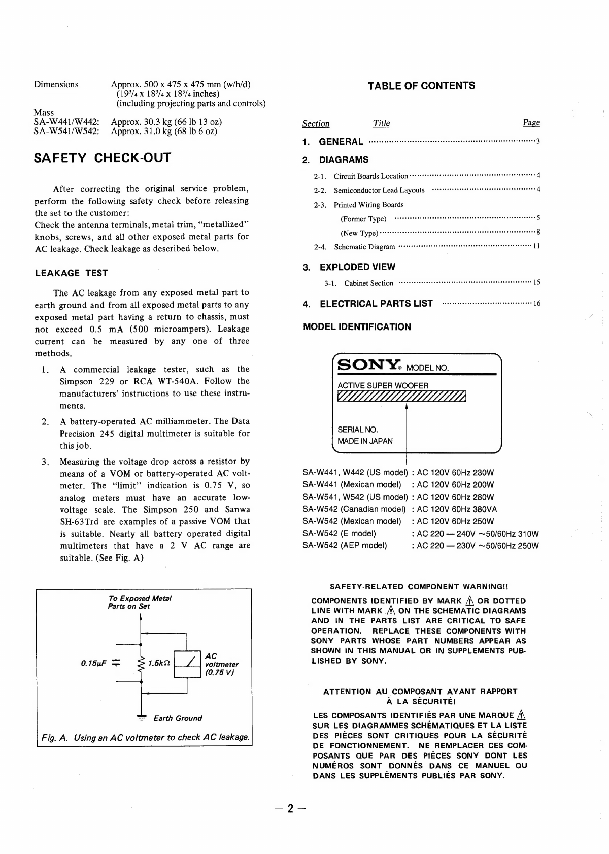
3.
Measuring
the
voltage
drop
across
a
resistor
by
means
of
a
VOM
or
battery-operated
AC
volt-
meter.
The
“limit”?
indication
is
0.75
V,
so
analog
meters
must
have
an
accurate
low-
voltage
scale.
The
Simpson
250
and
Sanwa
SH-63Trd
are
examples
of
a
passive
VOM
that
is
suitable.
Nearly
all
battery
operated
digital
multimeters
that
have
a
2
V
AC
range
are
suitable.
(See
Fig.
A)
To
Exposed
Metal
Parts
on
Set
AC
voltmeter
|
|
(0,75
v)
=
Earth
Ground
Using
an
AC
voltmeter
to
check
AC
leakage.
Approx.
500
x
475
x
475
mm
(w/h/d)
TABLE
OF
CONTENTS
Section
Title
Page
4.
GENERAL
-vvveseseesersssessseestenesneseneeceneeseescasetsntsgesenaees
3
2.
DIAGRAMS
4-1.
Circuit
Boards
Location
s+ts«*+sstsserseressssesesevnnsssaseenentonnersens
4
2-2,
Semiconductor
Lead
Layouts
<tstsresrsssesesesseseeseesteseesesees
4
2-3.
Printed
Wiring
Boards
(Former
Type)
cvrssretestrsseesessesseesnsseeessesensaseonssceeesseens
5
(New
Type)
srrrecssssnesrerssseeeeesrereesnssscezsrsaeneensssnecessneees
8
2-4.
Schematic
Diagram
srrrsrrrcsreetrsettersesstssrssseeseneesereereraeceens
11
3.
EXPLODED
VIEW
3-1.
Cabinet
Section
cecccrereereerreetsresssanseseesecseseneenneneneersees
15
4.
ELECTRICAL
PARTS
LIST
cvcceeccssceercceeterteeteeereees
16
MODEL
IDENTIFICATION
SON
YY:
movetno.
ACTIVE
SUPER
WOOFER
WLLLLLLLLLLLLLLLLLL
LLL
SERIAL
NO.
MADE
IN
JAPAN
SA-W441,
W442
(US
model)
:
AC
120V 60Hz
230W
SA-W441
(Mexican
model)
:
AC
120V
60Hz
200W
SA-W541,
W542
(US
model)
:
AC
120V
60Hz
280W
SA-W542
(Canadian
model)
:
AC
120V
60Hz
380VA
SA-W542
(Mexican
model)
:
AC
120V
60Hz
250W
SA-W542
(E
model)
:
AC
220
—
240V
~50/60Hz
310W
SA-W542
(AEP
model)
:
AC
220
—
230V
~50/60Hz
250W
SAFETY-RELATED
COMPONENT
WARNING!!
COMPONENTS
IDENTIFIED
BY
MARK
A
OR
DOTTED
LINE
WITH
MARK
A
ON
THE
SCHEMATIC
DIAGRAMS
AND
IN
THE
PARTS
LIST
ARE
CRITICAL
TO
SAFE
OPERATION.
REPLACE
THESE
COMPONENTS
WITH
SONY
PARTS
WHOSE
PART
NUMBERS
APPEAR
AS
SHOWN
IN
THIS
MANUAL
OR
IN
SUPPLEMENTS
PUB-
LISHED
BY
SONY.
ATTENTION
AU
COMPOSANT
AYANT
RAPPORT
A
LA
SECURITE!
LES
COMPOSANTS
IDENTIFIES
PAR
UNE
MARQUE
/\
SUR
LES
DIAGRAMMES
SCHEMATIQUES
ET
LA
LISTE
DES
PIECES
SONT
CRITIQUES
POUR
LA
SECURITE
DE
FONCTIONNEMENT.
NE
REMPLACER
CES
COM-
POSANTS
QUE
PAR
DES
PIECES
SONY
DONT
LES
NUMEROS
SONT
DONNES
DANS
CE
MANUEL
OU
DANS
LES
SUPPLEMENTS
PUBLIES
PAR
SONY.


