1
Table of Contents
Manual Structure
Purpose of this manual ............................................................................................... 5
Contents...................................................................................................................... 5
Relative manual.......................................................................................................... 6
1. Installation
1-1. Operating Conditions................................................................................... 1-1
1-2. Power Supply ...............................................................................................1-1
1-2-1. Voltage and Power Requirements ..............................................1-1
1-2-2. Power Cord .................................................................................1-1
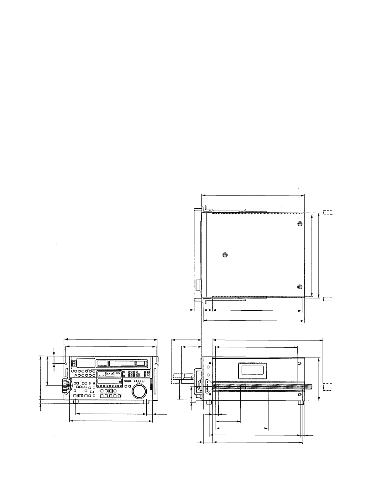
1-3. Installation Space .........................................................................................1-2
1-4. Supplied Accessories and Packing Materials List.......................................1-3
1-5. Rack Mounting.............................................................................................1-4
1-6. Matching Connectors ................................................................................... 1-6
1-7. Signal Outputs..............................................................................................1-7
1-8. Switch/Shorting Land Settings on the Boards............................................. 1-9
1-9. Search Dial Mode Switching .....................................................................1-14
1-10. Installation of BKDW-510/511 .................................................................1-16
1-11. Setup Menu ................................................................................................1-19
1-11-1. Setup Menu Items .....................................................................1-22
1-11-2. Details of the Setup Menu ........................................................1-23
1-11-3. Setting Check Sheet ..................................................................1-28
2. Service Overview
2-1. Notes on Power Supply Block.....................................................................2-1
2-1-1. Warning on Primary Circuit and Electric Shock........................ 2-1
2-1-2. Notes on Resetting the Circuit Breaker ...................................... 2-1
2-2. Removal/Installation of Cabinet..................................................................2-1
2-2-1. Cabinet Removal/Installation .....................................................2-1
2-2-2. Removal/Installation of Plate MD ..............................................2-3
2-2-3. Connector Panel Removal/Installation ....................................... 2-4
2-2-4. Power Supply Panel Removal/Installation .................................2-4
2-3. Cassette Compartment Removal/Installation ..............................................2-5
2-4. Locations of Main Part ................................................................................2-7
2-4-1. Printed Circuit Board Locations ................................................. 2-7
2-4-2. Main Mechanical Part Locations ..............................................2-11
2-4-3. Function and Location of Sensors ............................................2-12
2-5. LED Indicator Infomation on Boards........................................................2-14
2-6. How to Pull out/Push in the Lower Control Panel ....................................2-16